Multi Input Rectifier Structure for Hybrid
Wind-Solar Energy System
B.S.P.Sheema1, S.Nagaraj2
Assistant Professor, Dept. of EEE, P.B.College of Engineering, Chennai, Tamilnadu, India1
Assistant Professor, Dept. of EEE, P.B.College of Engineering, Chennai, Tamilnadu, India2
ABSTRACT: Other than hydropower, wind and photovoltaic energy holds the most potential to meet our energy demands. The common inherent drawback of wind and photovoltaic systems are their intermittent natures that make them unreliable. By combining these two intermittent sources and by incorporating Maximum Power Point Tracking (MPPT) algorithms, the system’s power transfer efficiency and reliability can be improved significantly. This paper presents a new multi input rectifier stage for a hybrid wind – solar energy system
KEYWORDS: Cuk converter, Sepic Converter, Maximum Power Point Tracking.
I.INTRODUCTION
The ever-increasing demand for conventional energy sources like coal, natural gas and crude oil is driving society towards the research and development of alternate energy sources. Many such energy sources like wind energy and photovoltaic are now well developed, cost effective and are being widely used, while some others like fuel cells are in their advanced developmental stage. These energy sources are preferred for being environmental-friendly. The integration of these energy sources to form a hybrid system is an excellent option for distributed energy production. Many such hybrid systems comprising of wind energy, photovoltaic and fuel cell have been extensively discussed in [1] [2] [3]. A fuzzy logic control for maximum power point tracking is employed for wind and photovoltaic energies in [1]. Digitally controlled multiphase switching dc-dc converters using PWM switching is introduced in [2] to obtain the required power from the fuel cells.
When a source is unavailable or insufficient in meeting the load demands, the other energy source can compensate for the difference. Several hybrid wind/PV power systems with MPPT control have been proposed and discussed in works [4]-[8]. Most of the systems in literature use a separate DC/DC boost converter connected in parallel in the rectifier stage as shown in Figure 1 to perform the MPPT control for each of the renewable energy power sources [4]-[7]. A simpler multi input structure has been suggested by [8] that combine the sources from the DC-end while still achieving MPPT for each renewable source. The structure proposed by [8] is a fusion of the buck and buck-boost converter. The systems in literature require passive input filters to remove the high frequency current harmonics injected into wind turbine generators [9]. The harmonic content in the generator current decreases its lifespan and increases the power loss due to heating [9].
II.ABOUTSEPICANDCUKCONVERTER
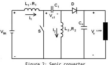
Figure 2: Sepic converter
The power module of the DC-DC SEPIC (single Ended Primary Inductor Converter) seen in Fig.2 can either step up or step down the input voltage, while maintaining the same polarity and the ground reference both for the input and output. When the power switch is turned on the first inductor, L1 is charged from the input voltage source and allows the second inductor to draw energy from the first capacitor, leaving the output capacitor to provide the load current. When the switch is turned off, the first inductor charges the capacitor C1 besides delivering current. It has greater efficiency hence large portion of the input power is transferred to the load.
Figure 3: CUK Converter
III. CIRCUIT DIAGRAM DESCRIPTION
The circuit diagram of the proposed multi input rectifier stage of a hybrid energy system is shown in Figur4,whereoneof the inputs is connected to the output of the PV array and the other input connected to the output of a generator. The fusion of the two converters is achieved by reconfiguring the two existing diodes from each converter and the shared utilization of the Cuk output inductor by the SEPIC converter. This configuration allows each converter to operate normally individually in the event that one source is unavailable
Figure 4: Multi input rectifier stage for a hybrid wind/PV system
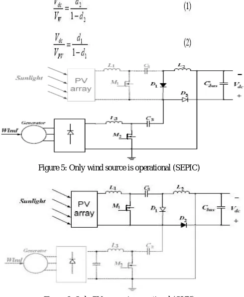
Figure 5 shows the case when only the wind source is available. In this case, D1 turns off and D2 turns on; the proposed circuit becomes a SEPIC converter and the input to output voltage relationship is given by (1). On the other hand, if only the PV source is available, then D2 turns off and D1 will always be on and the circuit becomes a Cuk converter as shown in Figure 6. The input to output voltage relationship is given by (2). In both cases, both converters have step-up/down capability, which provide more design flexibility in the system if duty ratio control is utilized to perform MPPT control.
Figure 5: Only wind source is operational (SEPIC)
Figure 6: Only PV source is operational (CUK)
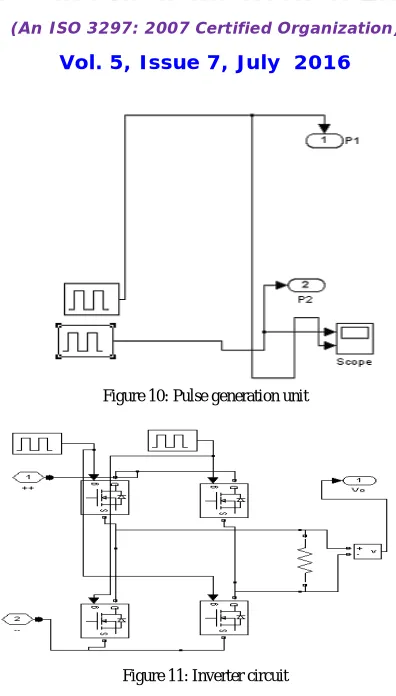
Figure 9 illustrates the wind source arrangement. Figure 10 illustrates the pulse generation unit for the two MOSFETs. The pulse generation unit generates pulses for Cuk and SEPIC converter. Figure 11 illustrates the inverter circuit. Inverter circuit converts the dc signal to ac, which can be used for the load.
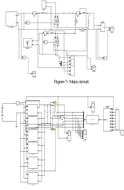
Figure 7: Main circuit
Figure 8: PV source arrangement
Figure 10: Pulse generation unit
Figure 11: Inverter circuit
IV.MPPTCONTROLOFPROPOSEDCIRCUIT
Figure 12: General MPPT flow chart for wind and PV
V.SIMULATION RESULTS
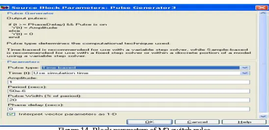
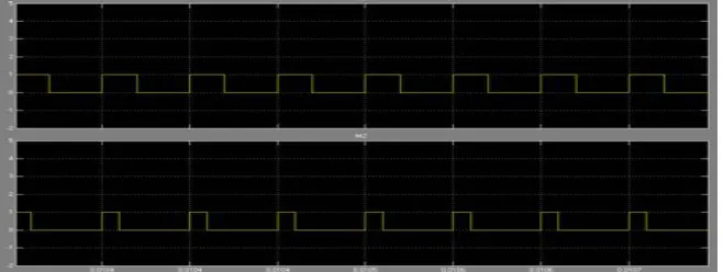
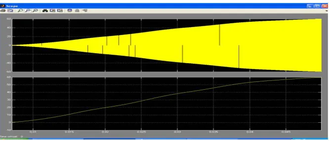
In this section, simulation results are given to verify that the proposed multi-input rectifier stage can support individual as well as simultaneous operation. Figures 13 and 14 illustrate the block parameters of pulse generators for M1 and M2 switches. The pulse width for M1 and M2 is 40 and 20 respectively. Figure 15 illustrates the pulse waveform of M1 and M2. Figure 16 illustrates the wind input source voltage. The input wind source voltage is 100V. Figure 17 illustrates the PV input source voltage. The input PV source voltage is 32V. Figure 18 shows the PV output current waveform. Figure 19 illustrates the inverter and converter output voltage waveform of simultaneous operation (Cuk-SEPIC fusion mode) of the two sources. The output voltage is 60V.
Figure 13: Block parameters of M1 switch pulse
Figure 15: Pulse Waveform of M1 and M2
Figure 16: Input wind source voltage
Figure 19: Inverter output voltage/ converter output voltage
VI.CONCLUSION
A new multi-input Cuk-SEPIC rectifier stage for hybrid wind/solar energy systems has been presented in this paper. The simulation results show that:
The Cuk and SEPIC converters are very effective in tracking the maximum power of the wind and photovoltaic sources; Additional input filters are not necessary to filter out high frequency harmonics;
With both wind and photovoltaic systems operating at their rated capacity, the system can generate power as high as 35 KW; Both renewable sources can be stepped up/down (supports wide ranges of PV and wind input);
MPPT can be realized for each source;
Individual and simultaneous operation is supported.
Separate controllers are not needed for two sources. Simulation results have been presented to verify the features of the proposed topology.
REFERENCES
[l] M.N. Eskander, T. F. El-Shatter and M.T. El-Hagry, "Energy Flow and Management of A Hybrid Wind/PV/Fuel Cell Generation System," Power Electronics SpecialistsConference, vol. 1, 23-27 June 2002, pp. 347- 353.
[2] K. Agbossou, S. Kelouwani, A. Anouar and M. Kolhe, "Energy Management of a Hydrogen-Based Stand-Alone Renewable Energy System By Using Boost and Buck Converters," Industry Applications Conference, 2004, vol. 4, 3-7 Oct. 2004, pp. 2786- 2793.
[3] J.J. Brey, A. Castro, E. Moreno and C. Garcia, "Integration of Renewable Energy Sources as an Optimised Solution for Distributed Generation,"
28th Annual Conference of theIndustrial Electronics Society 2002, vol. 4, 5-8 Nov. 2002, pp. 3355 – 3359.
[4] S.K. Kim, J.H Jeon, C.H. Cho, J.B. Ahn, and S.H. Kwon, “Dynamic Modeling and Control of a Grid-Connected Hybrid Generation System with Versatile Power Transfer,” IEEE Transactions on Industrial Electronics, vol. 55, pp. 1677-1688, April 2008.
[5] D. Das, R. Esmaili, L. Xu, D. Nichols, “An Optimal Design of a Grid Connected Hybrid Wind/Photovoltaic/Fuel Cell System for Distributed Energy Production,” in Proc. IEEE
[6] N. A. Ahmed, M. Miyatake, and A. K. Al-Othman, “Power fluctuations suppression of stand-alone hybrid generation combining solar photovoltaic/wind turbine and fuel cell systems,” in Proc. Of Energy Conversion and Management, Vol. 49, pp. 2711-2719, October 2008.
[7] S. Jain, and V. Agarwal, “An Integrated Hybrid Power Supply for Distributed Generation Applications Fed by Nonconventional Energy Sources,”
IEEE Transactions on Energy Conversion, vol. 23, June 2008.
[8] Y.M. Chen, Y.C. Liu, S.C. Hung, and C.S. Cheng, “Multi-Input Inverter for Grid-Connected Hybrid PV/Wind Power System,” IEEE Transactions on Power Electronics, vol. 22, May 2007.
[9] Dos Reis, F.S., Tan, K. and Islam, S., “Using PFC for harmonic mitigation in wind turbine energy conversion systems” in Proc. of the IECON 2004 Conference, pp. 3100- 3105, Nov. 2004