International Journal of Emerging Technology and Advanced Engineering
Website: www.ijetae.com (ISSN 2250-2459,ISO 9001:2008 Certified Journal, Volume 4, Issue 12, December 2014)
278
Comparison of Active & Reactive Power and Output Current
for K-rated and Conventional Transformer by MATLAB
SIMULINK
Manish Kumar Verma
1, Anushikha Sharma
2, Udit Kishor
3, Prof. Manab Kumar Sengupta
41,2,3,4Department of Electrical Engineering, Institute of Engineering & Technology-Alwar, India Abstract-- Under the influence of harmonics, generated by
non-linear loads, the source transformer get heated up due to various losses and the higher frequencies produce a reactive power also in the total transformer circuit with its load and by the co-existence of active & reactive power the output current also varies under various harmonic frequencies. In this paper the MATLAB simulation done on a K-rated and Conventional transformer to draw the comparison. The comparison clearly indicates the importance of using K-rated Transformer under the situation of non-linear load on the transformer. We have selected many frequencies for the simulation and harmonics with these frequencies are well taken care of.
Keywords—K-Rated Transformer, Harmonics, Non-linear load, Active & Reactive Power, MATLAB, Short Circuit Test of Transformer
I. INTRODUCTION
K-factor plays a vital role in designing transformers and to be more specific in the distribution transformer is discussed in this paper. Many aspects of this k-factor are not discovered and yet to be revealed by the power engineers. This paper aims to explain the relevance implication and application of k-rated transformer. For minimum iron losses, in pre electronic era, the designing of distribution transformers which were merely standard transformers, happened to be like that the load was mostly balanced lighting loads, induction motors and heating devices drawing sinusoidal currents. Only a very small percentage of the total current contributes harmonic currents though it was as old as electricity itself. Mercury arc rectifiers produce them which can be used in AC to DC conversion in railway electrification and also for variable speed drives in industry. The engineers felt an urgent need for the introduction of HVDC as the problems in synchronization, frequency equality, power factor matching and preponderantly due to huge losses in AC transmission were encountered in HVAC. A lot of harmonics in the load side which flow from load side to the source side occurs in HVDC system as it uses of SCR, GTO, and IGBT etc. So that makes quiet a sense to state that the load is non-linear in high power electronic devices system.
Moreover in the present era with the IT and IC revolution, the loads that are non-linear in nature injects considerable amount of harmonics in to the supply power system. It is seen that load faces as high as 115% harmonics and finally get damaged when feed with the supply system and mainly the distribution transformers. Harmonic currents are currents that have frequencies that are whole multiples of the fundamental frequency. [17]
The harmonic currents then superimpose on the fundamental current and finally result in the non-sinusoidal currents waveforms associated with non-linear loads. The effects of non-linear loads on the electric power system have now become a matter of concern. Non-linear loads are any load that draws current that is not sinusoidal and includes various equipment like arc furnaces, solid-state motor drives, UPS systems and increasingly becoming popular electronic power supply. Now-a-days power system is leaning towards non-linearity using non-linear loads which offers least impedance because of harmonic currents that flow towards the power source, through the path. [11]
II. K-RATED TRANSFORMER DESIGN FEATURES
International Journal of Emerging Technology and Advanced Engineering
Website: www.ijetae.com (ISSN 2250-2459,ISO 9001:2008 Certified Journal, Volume 4, Issue 12, December 2014)
279
Mentioned below are some of the design features that are incorporated in the designing of K-rated transformer. [17]A.Electric Circuit
1.K-rated transformers are to be designed for high neutral currents. As neutral current are considerably greater than the phase current the neutral terminal of transformer should be double the size of the outers (phases). The neutral current cable should be double the size to carry the larger harmonic current.
2.Oversized primary conductor are to be used considering the circulating harmonic currents around the delta winding though it may not be seen in main cables because of higher harmonic currents (3rd and above) the skin effect becomes pronounced. Hence the windings are composed of several smaller sized conductors.
3.Parallel and transposed conductors are used in secondary windings (l.v.) or multiple secondary winding to reduce the skin effect and associated ac resistances. Subdivision of conductor using strands radially reduces the eddy current loss due to the axial. Leakage flux similarly sub-division of conductor using strands axially reduces eddy current loss due to radial leakage flux.
It is essential that the ampere turns of both H.V. and L.V. windings should be perfectly balanced which reduces eddy current loss large balancing at may lead to high stray loss. Transposition especially on low voltage side eliminates circulating current between strands of a turn. This leads to positioning of strands of a turn such that leakage flux is the same thus equalizing the induced emf in each strand. [17]
B.Magnetic Circuit
1.The design should incorporate the reduction in core flux density to compensate harmonic voltage distortion i.e. designing a lower flux density (Bmax)
core and using a higher grade of CRGO even amorphous steel.
2.Studying the leakage flux and its path through computer analysis can do stray loss reduction.
3.The yoke clamp assembly should be shielded. Reduction of radial flux to tank side is to be achieved. Completely nonmetallic material for core clamping with magnetic shielding gives better results.
4.Suitable magnetic shunts of high permeability silicon steel are to be provided to deviate and divert the leakage flux away from structural steel parts such as yoke clamp tank etc. to avoid stray field loss.
All the points discussed above are of Consequences only for oil filled transformers, as the stray loss is generally not a consideration for dry type transformers as they are not very significant.
C.Dielectric Circuit
1. Insulation-oil immersed transformers are prepress board crepe paper all class a (105). The aging of insulation is very much dependent on temperature rise that is on loading. A decrease or increase of 6oc will double or half the life of transformer. Hence it is recommended to use a class h 150oc to withstand local overheating.
2. In oil filled transformers the clearance between windings and the tank is lesser as oil is an excellent dielectric. But the stray flux has easy access to tank plates. Which are solid unlike core that is laminated produce eddy current loss which is no negligible but considerable. Thus tank wall meant to dump out the heat itself becomes a source of heat and hence top oil temperature will be higher.
3. In dry type transformers, which are very much preferred in metropolis and cities to overcome fire hazard and minimize maintenance the need for tank, is very rare. Hence the stray field losses are very much limited to structural parts in the absence of tanks. Dry type design is better than oil type transformer considering the stray load loss effect besides safety and maintenance. [11]
III. SHORT CIRCUIT SIMULATION RESULT FOR
CONVENTIONAL AND K-RATED TRANSFORMER FOR 2
KVA &10KVA RESPECTIVELY
International Journal of Emerging Technology and Advanced Engineering
Website: www.ijetae.com (ISSN 2250-2459,ISO 9001:2008 Certified Journal, Volume 4, Issue 12, December 2014)
280
Fig.2 Frequency Vs X1 & X2 (2 KVA K-Rated Transformer)
Fig.3 Frequency Vs R1 & R2 (10 KVA Conventional Transformer)
Fig.4 Frequency Vs X1 & X2 (10 KVA K-Rated Transformer)
Fig.5 Short-Circuit Simulation Model for Transformer
IV. SIMULATION RESULTS OF ACTIVE &REACTIVE
POWER AND OUTPUT CURRENT ON DIFFERENT
FREQUENCIES FOR K-RATED AND CONVENTIONAL
TRANSFORMER BY MATLABSIMULINK
A.Simulation Results on 2 KVA Conventional & K-Rated Transformer
International Journal of Emerging Technology and Advanced Engineering
Website: www.ijetae.com (ISSN 2250-2459,ISO 9001:2008 Certified Journal, Volume 4, Issue 12, December 2014)
281
Fig.7 Simulation result on K-Rated Transformer (150 Hz)
Fig.8 Simulation result on Conventional Transformer (950 Hz)
Fig.9 Simulation result on K-Rated Transformer (950 Hz)
Fig.10 Simulation result on Conventional Transformer (1050 Hz)
Fig.11 Simulation result on K-Rated Transformer (1050 Hz)
International Journal of Emerging Technology and Advanced Engineering
Website: www.ijetae.com (ISSN 2250-2459,ISO 9001:2008 Certified Journal, Volume 4, Issue 12, December 2014)
282
Fig.13 Simulation result on K-Rated Transformer (1150 Hz)
B.Simulation Results on 10 KVA Conventional & K-Rated Transformer
Fig.14 Simulation result on Conventional Transformer (150 Hz)
Fig.15 Simulation result on K-Rated Transformer (150 Hz)
Fig.16 Simulation result on Conventional Transformer (1750 Hz)
Fig.17 Simulation result on K-Rated Transformer (1750 Hz)
International Journal of Emerging Technology and Advanced Engineering
Website: www.ijetae.com (ISSN 2250-2459,ISO 9001:2008 Certified Journal, Volume 4, Issue 12, December 2014)
[image:6.612.52.286.134.336.2]283
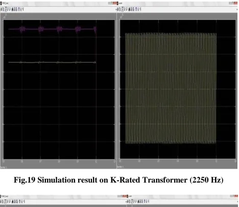
[image:6.612.52.287.322.465.2]Fig.19 Simulation result on K-Rated Transformer (2250 Hz)
Fig.20 Simulation result on Conventional Transformer (2350 Hz)
Fig.21 Simulation result on K-Rated Transformer (2350 Hz)
V. CONCLUSIONS
[image:6.612.52.287.487.644.2]It is observed from the above simulated graphical output that the K-rated transformer helps to mitigate the harmonics effect on its active power and reactive power delivery capability. Higher the frequencies the oscillations in the x-axis of the plot are more apparent in conventional and in K-rated Transformer with higher capacity found to be able to tackle the situations more efficiently. In short, we can definitely come to this observation that for 2 KVA and 10 KVA transformers with de-rated design i.e. K-Rated more suitable to tackle the bad effects of the harmonics coming from the non-linear load toward the source i.e. the transformers. The frequency versus reactance curve also display the indication that whenever we will get harmonics from the load side to source side K-Rated transformer are the best fitted to deal with this problem, which has become a challenge for the power engineers. Study of effect of various harmonics is a better approach for estimating the load loss of transformer. It is also observed that the effect of resonance in the core of the transformer and thereby giving a typical spectrum paths in source of higher harmonics. At some frequency say 1750 and 2250 (10 KVA K-rated) we observed and repetitive oscillation in the current display and the voltage indicate a pattern of travelling resonance wave as there is a phase propagation. Refer to Fig. 17 and Fig 19. At some frequency this display is straight line or bigger wavelength travelling wave. At 2350 Hz the observation is of magnetic oscillation. Refer to Fig. 21. Regarding the output current it is found in the plot that at higher frequencies the K-Rated Transformers give output in undistorted manner because of its ability to tackle the harmonics for the magnetizations of the transformer. But in conventional transformers the effect of the harmonics of higher frequencies creates the disturbance of the magnetization of the core which is responsible in delivering slightly modulated output.
REFERENCES
[1] Tony Hoevenaars, P.Eng., Vice President, MIRUS International Inc. ―How the Harmonic Mitigating Transformer Outperforms the K-Rated Transformer‖, Sept. 10, 1999.
[2] Philip J.A. Ling, P.Eng. ―Transformers and Associated Losses - The Opportunity for Savings‖ Powersmiths International Corp. 2001. [3] N.R Jayasinghe, J.R Lucas, K.B.I.M. Perera. ―Power System
International Journal of Emerging Technology and Advanced Engineering
Website: www.ijetae.com (ISSN 2250-2459,ISO 9001:2008 Certified Journal, Volume 4, Issue 12, December 2014)
284
[4] A F Zobaa, ―Practical Solutions for Harmonics Problems Produced in the Distribution Networks‖, J. Electrical Systems, PP 13-28, 2006. [5] I. Daut, H.S. Syafruddin, Rosnazri Ali, M. Samila, H. Haziah, ―The Effects of Harmonic Components on Transformer Losses of Sinusoidal SourceSupplying Non-Linear Loads‖, American Journal of Applied Sciences, PP 2131-2133, 2006.
[6] Syafruddin Hasan, Ismail Daut, Soib Taib, ―K-Factor due to Implementing of DC Unbalanced/Balanced of a Transformer‖, Proceedings of Asia-Pacific Conference on Applied Electromagnetics, December 2007.
[7] Kiran Deshpande, Prof.Rajesh Holmukhe, Yogesh Angal, ―K-Factor Transformers and Non-linear Loads‖, 2010.
[8] L. W. Pierce, ―Transformer design and application considerations for non-sinusoidal load currents,‖ IEEE Trans. on Industry Applications, vol. 32, no. 3, pp. 633–645, May/June 1996.
[9] T. Batan, ―Real-time monitoring and calculation of the de-rating of single-phase transformers under (non)sinusoidal operations‖ Ph.D. thesis, University of Colorado at Boulder, Dec. 1998.
[10] Linden W. Pierce ―Transformer Design and Application Considerations for Non-sinusoidal Load Currents‖ IEEE Transactions on Industry Applications Vol.32 No. 2, PP 633-645 May/June 1996.
[11] Jian Zheng ―Transformer ac winding resistance and De-rating when supplying harmonic-rich Current‖ MS Report, Michigan Tech University, 2000.
[12] Salih, T.M. et al., 2000. The Effect of the harmonic components upon transformer active losses in case of (non) sinusoidal sources and (non) linear loads. Department of Electrical Engineering Yildiz Technical University, Istambul, Turkey.
[13] Bora ACARKAN and Osman KILIC, ―Electrical Harmonics Modeling of Office Equipments Using Matlab and Simulink‖. [14] Saffet ayasun, chika o. Nwankpa, ―Transformer Tests Using
MATLAB/Simulink and Their Integration Into Undergraduate Electric Machinery Courses‖, Wiley Periodicals, Inc. Comput Appl Eng Educ 14: 142-150, 2006.
[15] SIMULINK, Model-Based and System-Based Design, Using Simulink, MathWorks Inc. Natick, MA, 2000.
[16] R. Patel, T. S. Bhatti, and D. P. Kothari, MATLAB/ Simulink-based transient stability analysis of a multimachine power system, Int J Electr Eng Educ 39 (2003), 320-336.