University of South Carolina
Scholar Commons
Theses and Dissertations
12-16-2013
Modified Sodium Diuranate Process For the
Recovery of Uranium From Uranium Hexafluoride
Transport Cylinder Wash Solution
Austin Dean Meredith
University of South Carolina - Columbia
Follow this and additional works at:https://scholarcommons.sc.edu/etd
Part of theNuclear Engineering Commons
This Open Access Dissertation is brought to you by Scholar Commons. It has been accepted for inclusion in Theses and Dissertations by an authorized administrator of Scholar Commons. For more information, please [email protected].
Recommended Citation
Meredith, A. D.(2013).Modified Sodium Diuranate Process For the Recovery of Uranium From Uranium Hexafluoride Transport Cylinder
Modified Sodium Diuranate Process for the Recovery of Uranium from Uranium Hexafluoride Transport Cylinder Wash Solution
by
Austin Dean Meredith
Bachelor of Science
University of South Carolina, 2013
Submitted in Partial Fulfillment of the Requirements
For the Degree of Master of Science in
Nuclear Engineering
College of Engineering and Computing
University of South Carolina
2013
Accepted by:
Travis W. Knight, Director of Thesis
Thad Adams, Reader
ii
iii
A
CKNOWLEDGEMENTSSpecial thanks to Ron Noe for his help with this project and his invaluable
expertise in the fields of nuclear chemistry and chemical engineering.
Thanks to Dr. Elizabeth Bair and the Center for Elemental Mass Spectrometry at
the University of South Carolina for analyzing the product and filtrate samples.
Thanks to Seung Min Lee for his assistance with the Netzsch TG 409 CD
thermobalance.
Thanks to Dr. Travis W. Knight and Dr. Thad Adams for their assistance with this
thesis, in time commitments, direction, scope, and feedback.
Special thanks also to my parents, Craig and Rachelle Meredith, my sister,
Heather Meredith, and my wife, Meagan Meredith, without whom I would not be the
man I am today.
iv
A
BSTRACTUranium hexafluoride (UF6) containment cylinders must be emptied and washed
every five years in order to undergo recertification, according to ANSI standards. During
the emptying of the UF6 from the cylinders, a thin residue, or heel, of UF6 is left behind.
This heel must be removed in order for recertification to take place.
To remove it, the inside of the containment cylinder is washed with acid and the
resulting solution generally contains three or four kilograms of uranium. Thus, before the
liquid solution can be disposed of, the uranium must be separated. A modified sodium
diuranate (SDU) uranium recovery process was studied to support development of a
commercial process. This process was sought to ensure complete uranium recovery, at
high purity, in order that it might be reused in the nuclear fuel cycle. An experimental
procedure was designed and carried out in order to verify the effectiveness of the
commercial process in a laboratory setting.
The experiments involved a small quantity of dried UO2F2 powder that was dosed
with 3wt% FeF3 and was dissolved in water to simulate the cylinder wash solution. Each
experiment series started with a measured amount of this powder mixture which was
dissolved in enough water to make a solution containing about 120 gmU/liter.
The experiments involved validating the modified SDU extraction process. A
potassium diuranate (KDU) process was also attempted. Very little information exists
regarding such a process, so the task was undertaken to evaluate its efficacy and
v
as compared to a sodium process. However, the KDU process ultimately proved
ineffective and was abandoned.
Each of the experiments was organized into a series of procedures that started
with the UO2F2 powder being dissolved in water, and proceeded through the steps needed
to first convert the uranium to a diuranate precipitate, then to a carbonate complex
solution, and finally to a uranyl peroxide (UO4) precipitate product. Evaluation of
operating technique, uranium recovery efficiency, and final product purity were part of
each experiment. Evaluation of a technique for removing fluoride from the diuranate
precipitation byproduct filtrate using granular calcite was also included at the end of the
uranium recovery testing.
It was observed that precipitation of sodium diuranate (SDU) was very nearly
complete at a pH of 11-12, using room temperature conditions. Uranium residuals in the
filtrate ranged from 3.6 – 19.6 ppm, meaning almost complete precipitation as SDU. It
was postulated and then verified that a tailing reaction occurs in the SDU precipitation,
which necessitates a digestion period of about 2 hours to complete the precipitation.
Further, it was shown, during this phase of the process, that a partial precipitation step at
pH 5.5 did not adequately separate iron contamination due to an overlap of uranium and
iron precipitations at that condition.
Carbonate extraction of the SDU required an extended (3-4 hours) digestion at
40°C and pH 7-8 to complete, with sodium bicarbonate found to be the preferred
extractant. The carbonate extraction was also proven to successfully separate the iron
vi
Potassium-based chemistry did produce a potassium diuranate (KDU) analogue of
SDU, but the subsequent carbonate extraction using either potassium bicarbonate or
potassium carbonate proved to be too difficult and was incomplete. The potassium
testing was terminated at this step.
The uranyl peroxide precipitation was found to operate best at pH 3.5 – 4.0, at
room temperature, and required an expected, extended digestion period of 8 -10 hours.
The reaction was nearly complete at those conditions, with a filtrate residual ranging
from 2.4 to 36.8 ppmU. The uranyl peroxide itself was very pure, with impurity averages
at a very low 0.8 ppmNa and 0.004 ppmFe. ASTM maximum levels are 20 ppmNa and
150 ppmFe.
Fluoride removal from the SDU precipitation filtrate required multiple passes of
the solution through a calcite bed with acid additions to adjust the pH back down to
below 6 before each pass to allow the removal reaction to proceed. This result was a
modification of the single pass technique that was planned due to the apparent shutdown
of the NaF/calcite reaction at pH above about 10.
Conclusions drawn from the testing were that the results demonstrated a workable
and effective series of processing steps. Techniques developed from the tests will make
vii
T
ABLE OFC
ONTENTSACKNOWLEDGEMENTS ... iii
ABSTRACT ... iv
LIST OF TABLES ... viii
LIST OF FIGURES ...x
LIST OF ABBREVIATIONS ... xiv
CHAPTER 1:INTRODUCTION ...1
CHAPTER 2:LITERATURE REVIEW ...6
CHAPTER 3:METHODOLOGY ...13
CHAPTER 4:RESULTS AND DISCUSSION ...26
CHAPTER 5:CONCLUSIONS ...82
viii
L
IST OFT
ABLESTable 2.1 Maximum Heel Allowed by Cylinder Type ...7
Table 2.2 Impurity Elements and Maximum Concentration Limits ...10
Table 4.1 First Test Series, SDU Precipitation ...26
Table 4.2 Second Test Series, Partial Precipitation of Iron Sediment Settling ...30
Table 4.3 Second Test Series, SDU Precipitation ...32
Table 4.4 Second Test Series, SDU Settling, No Digestion Period ...33
Table 4.5 Second Test Series, SDU Settling, With Digestion Period...35
Table 4.6 Second Test Series, First Half, UO4 Settling Test ...42
Table 4.7 Second Test Series, Second Half, UO4 Settling Test ...44
Table 4.8 First Test Series, Auxiliary Testing, UO4 Settling...46
Table 4.9 Third Test Series, KDU Precipitation ...49
Table 4.10 Third Test Series, KDU Settling ...50
Table 4.11 Third Test Series, Additional KDU Settling ...52
Table 4.12 Third Test Series, First Uranyl Carbonate Extraction Titration ...54
Table 4.13 Fourth Test Series, KDU Precipitation ...59
Table 4.14 Fifth Test Series, SDU Precipitation...60
Table 4.15 Fifth Test Series, SDU Settling...62
Table 4.16 Fifth Test Series, Batch 1, UO4 Precipitation ...67
Table 4.17 Fifth Test Series, Batch 1, UO4 Settling ...68
ix
Table 4.19 Fifth Test Series, Batch 2, UO4 Settling ...70
Table 4.20 Fifth Test Series, Batch 3, UO4 Precipitation ...72
Table 4.21 Fifth Test Series, Batch 3, UO4 Settling ...72
Table 4.22 pH Change with Each Pass through Calcite Column ...75
Table 4.23 Mass UO4·nH2O from Each Series ...77
Table 4.24 Mass of Uranium before Recovery Process ...77
Table 4.25 Drying Data...78
Table 4.26 Mass of Uranium Recovered ...78
Table 4.27 Calcining Data ...79
Table 4.28 Mass of Uranium Recovered through Calcination ...79
Table 4.29 Residual Uranium Content in SDU and UO4 Filtrates ...80
x
L
IST OFF
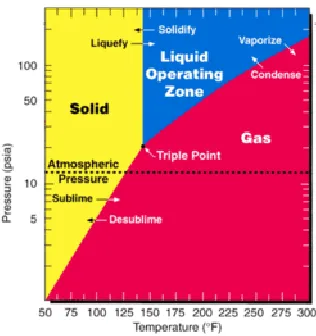
IGURESFigure 1.1 UF6 Phase Diagram ...1
Figure 1.2 UF6 crystals in a small glass ampoule ...2
Figure 1.3 48Y UF6 Container ...3
Figure 3.1 SDU Process for recovering uranium from UF6 containment cylinder wash solution ...15
Figure 3.2 Experiments 2 & 3 ...17
Figure 3.3 Vacuum apparatus system ...18
Figure 3.4 Experiments 4 & 5 ...19
Figure 3.5 Experiment 6 ...21
Figure 3.6 Experiment 7 ...22
Figure 3.7 Modified Recovery Process ...24
Figure 4.1 Graph of First Test Series, SDU Precipitation pH Curve, pH v. Volume NaOH Added (mL) ...27
Figure 4.2 Powdered UO2F2 dosed with 3wt% FeF3, and the powder dissolved in water ...27
Figure 4.3 Titration with NaOH...28
Figure 4.4 First Test Series SDU after overnight settling ...29
Figure 4.5 Settling of Fe(OH)3 Solid ...30
Figure 4.6 Siphoning off supernate liquid before filtering out Fe(OH)3 solids ...31
xi
Figure 4.8 Titration set-up ...33
Figure 4.9 SDU settling, no digestion period ...34
Figure 4.10 Graph of the Estimated Supernate Volume (%) over Time (min) for Second Test Series, SDU Settling, Without a Digestion Period ...34
Figure 4.11 Graph of the Supernate Volume (mL) over Time (min) for Second Test Series, SDU Settling, With 2 hour Digestion Period ...36
Figure 4.12 Second Test Series, SDU settling after 2 hour digestion...36
Figure 4.13 Filtration set-up, SDU Filter Cake, SDU filtrate (NaF Solution) ...37
Figure 4.14 SDU Filter Cake in Beaker, Sodium Carbonate/Bicarbonate mixture (pH=10), Slurry of SDU and 300 mL of 10% Na2CO3 solution ...38
Figure 4.15 Uranyl Carbonate Solution after overnight settling ...38
Figure 4.16 Final UCO3 Products ...39
Figure 4.17 UO4 Precipitation...41
Figure 4.18 Graph of Supernate Volume (mL) over Time (min) for Second Test Series, First Half, UO4 Settling ...42
Figure 4.19 Settling of Second Test Series, First Half, UO4 ...43
Figure 4.20 Filtration of Second Test Series, First Half, UO4 ...43
Figure 4.21 Uranyl Carbonate Solution prepared from First Test Series SDU ...46
Figure 4.22 Graph of Supernate Volume (mL) over Time (min) for First Test Series, Auxiliary Testing, UO4 Settling ...47
Figure 4.23 First Test Series, Auxiliary Testing, UO4 Settling ...47
Figure 4.24 First Test Series, Auxiliary Testing, UO4 and filtrate ...48
Figure 4.25 Graph of pH v. Time (min) for Third Test Series, KDU Precipitation ...50
Figure 4.26 Graph of Supernate Volume (mL) over Time (min) for Third Test Series, KDU Precipitate Settling ...51
xii
Figure 4.28 Third Test Series KDU Extraction after settling ...53
Figure 4.29 Third Test Series, First Carbonate Extraction ...55
Figure 4.30 Re-slurried solids from Third Test Series, first carbonate extraction ...56
Figure 4.31 Third Test Series, second carbonate extraction filtrate and Solids from second carbonate extraction, re-slurried in water ...56
Figure 4.32 Attempted third carbonate extraction ...57
Figure 4.33 Third Test Series, Third Carbonate Extraction filtration ...58
Figure 4.34 Graph of Fifth Test Series, SDU Precipitation pH Curve, pH v. Volume NaOH Added (mL) ...61
Figure 4.35 Fifth Test Series SDU Precipitation ...61
Figure 4.36 Graph of Volume Supernate Liquid (mL) over Time (min) for Fifth Test Series, SDU Settling ...62
Figure 4.37 Fifth Test Series SDU Settling ...63
Figure 4.38 Fifth Test Series SDU Carbonate Extraction 1...65
Figure 4.39 Fifth Test Series SDU Carbonate Extraction 2...65
Figure 4.40 Fifth Test Series SDU Carbonate Extraction 3...66
Figure 4.41 Fifth Test Series, Batch 1, UO4 precipitation ...67
Figure 4.42 Graph of Volume Supernate Liquid (mL) over Time (min) for Fifth Test Series, Batch 1, UO4 Settling...68
Figure 4.43 Fifth Test Series, Batch 1, UO4 settling ...69
Figure 4.44 Fifth Test Series, Batch 1, UO4 filter cake and filtrate ...69
Figure 4.45 Graph of Volume of Supernate Liquid (mL) over Time (min) for Fifth Test Series, Batch 2, UO4 Settling...71
Figure 4.46 Fifth Test Series, Batch 2, UO4 filter cake and filtrate ...71
xiii
Figure 4.48 Fifth Test Series, Batch 3, UO4 filter cake and filtrate ...73
Figure 4.49 Calcite column apparatus ...74
xiv
L
IST OFA
BBREVIATIONSADU ... Ammonium Diuranate
ANSI ... American National Standards Institute
ASTM ... American Society for Testing and Materials
CFR ... Code of Federal Regulations
KDU ... Potassium Diuranate
LEU ...Low Enriched Uranium
1
C
HAPTER1:
I
NTRODUCTIONUranium hexafluoride (UF6), known in the nuclear industry as “hex,” is a
chemical compound used in the conversion, enrichment, transportation, and storage of
uranium. It is an incredibly useful compound because it has a unique triple point, which
makes it perfectly suited for most applications. The triple point of UF6 lies at a mere
64.05°C (147°F) and just above standard atmospheric pressure—at about 20 psia (1).
Thus, it can readily be converted between its solid, liquid, and gas phases, making it easy
to handle, transport, enrich, and store.
2
UF6 is usually transported as a solid and then quickly converted to liquid or gas
for removal from its transport container. It can then be easily put to use, most often for
enrichment at gaseous diffusion or centrifuge enrichment facilities (3). Also, because
there are not many uses for the large amounts of depleted uranium generated at this time,
UF6 is used as a chemical means to store it long-term.
Figure 1.2 – UF6 crystals in a small glass ampoule (4)
As a solid, UF6 is a white, crystalline material. It is inert in dry air and will not
react with oxygen, nitrogen, or carbon dioxide. However, it is highly corrosive and
exceptionally reactive with water—the humidity in the air being enough for it to react.
As UF6 reacts with water, it is quickly converted to uranyl fluoride (UO2F2) and
hydrogen fluoride (HF). In aqueous solution, whether in water or even humid air,
hydrogen fluoride forms hydrofluoric acid, which is incredibly toxic and extremely
corrosive, even in low concentrations. This means that stringent measures must be taken
when transporting UF6, not only to protect the public from the radiation and toxicity
hazards inherent with uranium, but also from the health hazards of HF. (5)
To mitigate these risks and make the transport of UF6 safe, easy, and
cost-effective, special containment vessels have been designed for its shipment. These
3
transported and the needs leading to its use. The smallest certified containers are only 1.5
inches in diameter, hold a maximum of 1lb of UF6, and are made of nickel or
nickel-copper alloy. The largest containers are 48 inches in diameter, can hold upward of 14
metric tons of UF6, and are made of stainless steel (6). The two basic sizes that have
been developed over the years to transport commercial quantities of UF6 are a 30 inch
diameter cylinder that holds about 2.25 metric tons of solid UF6 (30B container), and a 48
inch diameter cylinder that holds either 10 metric tons (48X container) or 14 metric tons
(48Y container) of UF6, depending on its length. The current predominant designs are
the 30B and 48Y containers.
Figure 1.3 – 48Y UF6 Container (7)
No matter the size, each of the container designs is a metal cylinder, with rounded
ends, specially designed to hold solid UF6 for decades. They are designed to meet or
exceed very strict ANSI regulations, and during transportation they are fitted with
4
The expected, worldwide uranium requirements for “commercial nuclear
generating capacity and reactor-related uranium requirements” for 2011 were 65,180
metric tons of natural uranium, and that number is expected to increase to somewhere
between 69,000 and 76,000 metric tons by 2015 (9). All of this uranium must be
converted, enriched, and fabricated into fuel before it can be used, and the only way to
transport it currently is in the described containment cylinders. Thousands of metric tons
of UF6 are handled and transported on a yearly basis (3).
About 6,600, 30B cylinders, containing low enriched uranium (LEU, <5 wt%
235U), are transported each year, moving UF6 from enrichment plants to fuel fabrication
plants, where the UF6 is converted into UO2 for power reactor fuel. About 9,100, 48X
and 48Y cylinders each year are used each year to transport natural UF6 from UF6
conversion plants to enrichment plants (10). About 90,000 48X, 48Y and 48G (a
thinner-walled version of the 48Y) cylinders are used for long-term storage of depleted UF6
tailings from enrichment plants. Many of this last group of cylinders have long exceeded
their transport certification limit and cannot be moved out of their storage sites without
special dispensation by government authorities or recertification.
The UF6 being transported is highly corrosive and poses serious health risks
should it be released to the environment. So, the transport cylinders must be inspected
regularly—at “intervals not to exceed 5 years”—to ensure that there are no “leaks,
corrosion, cracks, bulges, dents, gouges, defective valves, damaged stiffening rings or
skirts, or other conditions that, in the opinion of the qualified inspector, render it unsafe
or unserviceable in its existing condition” (11). Thus, in order to maintain the credentials
5
recertified every five years, using a series of physical tests designed to demonstrate the
integrity of the cylinder. Successful completion of the physical testing recertifies the
cylinder for five additional years of service.
When the time comes for a container’s recertification, it is first heated in order to
vaporize the UF6 within so that it can be extracted from the container. Empty cylinders
contain a small residue of UF6, called a “heel,” which must be washed from the cylinder
before testing can begin. This heel is usually 3-4 kg—though regulations allow for up to
22.7 kg—of solid UF6 that has adhered to the cylinder walls due to corrosion. Many
different techniques, operating procedures, additives, and approaches to cylinder washing
have been developed and are in use throughout the world, with varying degrees of
efficacy. Most of these approaches involve the use of a caustic chemical wash that pulls
the uranium off of the inside of the container. The wash solution must then be stripped of
uranium so that it can meet disposal standards.
This study was conducted to evaluate the efficacy of a sodium diuranate process
that was designed to completely remove the uranium from a cylinder wash solution, and
recover it as highly pure, solid uranyl peroxide, which can be put back into the nuclear
6
C
HAPTER2:
L
ITERATURER
EVIEWTitle 49 of the Code of Federal Regulations, Part 173.420 (49CFR173.420)
establishes the guidelines for the transportation of UF6 in the United States. This section
requires that packages for the transport of UF6 must conform to American National
Standard N14.1 (ANSI N14.1) (12), which sets standards for all aspects of UF6
transportation cylinders, covering everything from cylinder design and materials, to
testing, certification, and transportation.
ANSI N14.1, Section 6.3.2 requires that “all cylinders shall be periodically
inspected and tested throughout their service life at intervals not to exceed 5 years” and
that “cylinders shall not be refilled [after each five-year interval] until they are properly
reinspected, retested, and restamped.” This required, periodic inspection includes
internal and external examinations of the cylinder, hydrostatic strength testing, and air
leak testing. Should anything about a cylinder be “found to…, in the opinion of [a]
qualified inspector, render it unsafe or unserviceable,” it must be removed from service
for repair or replacement. (11)
Section 8.1.2 of ANSI N14.1 allows for the transport of empty UF6 cylinders that
contain less than a specified weight of UF6 residue, or heel. This allowed weight varies
according to container size and percent enrichment, but does not exceed a heel of 50 lbs
at 4.5 wt% U235—the weight allowed to be transported in 48X and 48Y containers (13).
7
Table 2.1 – Maximum Heel Allowed by Cylinder Type
Cylinder Model Number Heel (lb) Heel (kg) Max U235, wt%
5A or 5B 0.1 0.045 100
8A 0.5 0.227 12.5
12A or 12B 1 0.454 5
30B 25 11.3 5
48X 50 22.7 4.5
48Y 50 22.7 4.5
48G, 48H, 48O, 48OM 50 22.7 1
Allied or 48T 50 22.7 1
However, when the time comes for recertification, the inside of the container must
be thoroughly cleaned and the heel must be removed, so that the cylinder can be fully,
properly, and safely inspected. The uranium heel is removed with an acidic solution,
which must then be processed to recover the uranium, which can afterward be processed
into a form and purity that will allow it to be reused in the nuclear fuel cycle.
Many milling processes use an acidic solution to leach uranium from its ores so
that it can be processed into yellow cake. The acidic solution is treated with an alkaline
solution to strip the uranium and convert it into an alkali form, which is then processed
with more acid and precipitated with hydrogen peroxide into a uranium oxide yellow
cake (14).
A similar process is used to convert the uranium oxide to UF6. To produce UF6,
the yellow cake is dissolved in nitric acid, forming a uranyl nitrate solution. A selective
solvent extraction is used to remove impurities, and the resulting, purified uranyl nitrate
8
hydroxide, potassium hydroxide, etc.) to form an alkali diuranate. This substance is then
calcined, reduced, hydrofluorinated, and fluorinated in order to produce UF6. (15)
The process to recover uranium from a UF6 solution as a usable uranium oxide
works much like the conversion process in reverse, and uses similar techniques to the
milling process. A liquid, acidic UF6 solution is treated with an alkali solution to form an
alkali diuranate solid. This diuranate goes through a carbonate solvent extraction,
wherein the diuranate solid is mixed with a carbonate solution, to strip the uranium from
any present impurities. The resulting uranyl carbonate complex can then be precipitated
with hydrogen peroxide as uranyl peroxide (16), which can be calcined into usable
yellow cake.
There are many processes available to convert uranium into an alkali form, but
according to Murty, et al., the ammonium diuranate (ADU) process “has been the most
intensively followed and investigated” (17). Sodium diuranate (SDU) processes have
also been widely used, but have generally been discarded because of the potential for
sodium contamination. Murty, et al., and Manna, Roy and Joshi, point out that the
properties of the diuranate precursor, which are gained from the processes that make it,
are passed on to the final uranium dioxide product (17, 18).
Since SDU and ADU are chemically analogous, it is of great benefit to understand
the importance of ADU in the nuclear fuel cycle. ADU is an intermediate compound in
the milling and conversion of uranium. It is generally produced by either a uranyl nitrate
or a uranyl fluoride process, where the uranyl compound is reacted with a gaseous
ammonia or an aqueous ammonium hydroxide. The ADU solid formed can then be
9
readily converted into UF6 for storage and transport or reduced to UO2 for fuel
fabrication. The only thing necessary to produce SDU instead of ADU, is the use of
sodium compounds as opposed to ammonium compounds (i.e. NaOH instead of
NH4OH).
The Triple Altura Laboratory (LTA) in Argentina uses a sodium diuranate process
to recover uranium from scrap that has been generated by the manufacture of
uranium/aluminum alloy fuel elements. In order to recover the nuclear material from the
scrap, LTA uses a three-step process. First, the material from which the uranium is to be
recovered is dissolved using NaNO3 and NaOH solutions. This alkaline dissolution
converts the aluminum to soluble sodium aluminate and the uranium to insoluble sodium
diuranate (Na2U2O7). The second step is to separate the sodium diuranate from the liquid
via filtration, and then eliminate any excess aluminum with a wash each of NaOH and
deionized water. The solid is then, finally, dissolved with HNO3 to form an
aluminum-free, uranyl nitrate solution. The process researched follows steps very similar to those
used by LTA, in that an alkaline dissolution would be used to separate the impurities and
uranium from the initial solution, and then a carbonate (rather than nitrate) extraction
dissolution would be used to recover the uranium from the SDU. (19)
In order for uranium oxides to be used for direct hydrogen reduction to nuclear
grade uranium dioxide, they must conform to the standards set forth in ASTM C1348.
Table 1 of ASTM C1348 gives a list of impurity elements and their maximum allowable
concentrations in the uranium if it is to be used for eventual fuel fabrication (20). This
10
Table 2.2 – Impurity Elements and Maximum Concentration Limits
Element Maximum Concentration Limit of Uranium, µg/gU
Aluminum 50
Barium 5
Beryllium 100
Bismuth 3
Calcium + Magnesium 100
Carbon 100
Chlorine 100
Chromium 100
Cobalt 80
Copper 100
Fluorine 100
Iron 150
Lead 40
Manganese 50
Molybdenum 200
Nickel 80
Phosphorus 100
Silicon 200
Sodium 20
Tantalum 200
Thorium 10
Tin 50
Titanium 50
Tungsten 100
Vanadium 10
Zinc 20
The limit for sodium contaminants is 20µg/gU, and must be held below this level
because sodium contamination can cause cracking in reactor fuel. As SDU processes use
large amounts of sodium, they typically have to be carried out more slowly and have to
be more carefully monitored than ADU processes in order to ensure an acceptable final
product. Thus, most of the current processes use ammonia to form ADU. Since fuel
11
cylinders and use ammonia in their processes, an ADU process is also used to recover
uranium from the UF6 cylinder wash solution.
An SDU process was designed that would recover all of the uranium from the
cylinder wash solution, separate all of the iron contamination from the recovered
uranium, and allow ensure sodium content less than 20µg/gU in the final uranium oxide,
meeting the requirements of ASTM C1348. In this process, a cylinder wash solution
would be titrated with sodium hydroxide (NaOH) to a pH of 4.5-5.5, in order to remove
iron contaminants. The iron would precipitate out of solution as solid ferric hydroxide
(Fe(OH)3), which usually precipitates at about pH 3.5 (21). Literature indicates that the
uranium should not fully precipitate as SDU (Na2U2O7) until around pH 12.0 (22, 23),
allowing for full removal of the iron and subsequent precipitation of the SDU with the
addition of more NaOH. This SDU would undergo a carbonate solvent extraction with a
sodium carbonate/sodium bicarbonate solution, in order to strip the uranium from any
sodium impurities, as a uranyl carbonate complex solution (24). The uranium would then
be precipitated out of the solution as uranyl peroxide solid (UO4·nH2O), by titrating it
with hydrogen peroxide (H2O2) and nitric acid (HNO3), which is used to keep the pH in
the range of 2.5-5.5, which the literature suggests is the optimal range for the reaction
(16, 25).
Since the uranyl peroxide from this process is precipitated as a hydrate, water
trapped in the final solid could result in an incorrect calculation of recovered uranium if a
simple mass balance is used. Thus, measures other than simply weighing, or air drying
and then weighing, would have to be taken to verify complete uranium recovery, either
12
Both measures were used in order to determine the mass of uranium recovered. While a
temperature of 400-450C was chosen to dry the uranyl peroxide, work by Morais, et al.,
and Bonini, et al., showed that a temperature of at least 800°C was necessary to fully
calcine the UO4·nH2O and convert it to U3O8 (19, 25). Thus it was calcined at 1000°C
13
C
HAPTER3:
M
ETHODOLOGYA modified sodium diuranate (SDU) process was designed to extract the uranium
from UF6 cylinder wash solution, carry it through a purification and conversion process,
and then recover it as uranyl peroxide (UO4) solid. An experimental procedure was
developed and carried out in order to study the process and evaluate its efficacy in a
laboratory setting.
The process was designed to first use sodium hydroxide to precipitate any iron
contamination from the wash solution, according to Eqn. 3.1, which iron would then be
filtered from the solution.
( ) ( ) (3.1)
Then more sodium hydroxide would be used to precipitate the uranium out of the
solution as solid SDU, following the reaction given in Eqn. 3.2.
( ) (3.2)
The intermediary precipitation of the iron was thought to be possible because the
iron should react and precipitate at a much lower pH than the uranium. The SDU would
go on to be mixed with a sodium carbonate/bicarbonate solution to extract the uranium as
14
shorthand notations for “uranyl carbonate complex solution throughout the study), as
shown below in Eqn. 3.3.
( ) (3.3)
The uranium would then be precipitated out of the carbonate solution with nitric
acid and hydrogen peroxide, as solid UO4.
( ) ( ) (3.4)
( ) ( ) (3.5)
The process was developed to extract all of the uranium from the wash solution
and carry it through to the production of UO4, and the UO4 should be devoid of any iron
15
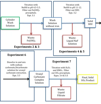
Figure 3.1 – SDU Process for recovering uranium from UF6 containment cylinder wash solution
A similar, potassium diuranate (KDU) process was also investigated, using
potassium hydroxide instead of sodium hydroxide to form KDU instead of SDU, and
using potassium carbonate/bicarbonate to extract the uranium as uranyl carbonate.
Experimentation was carried out to see if this would make a viable recovery process.
Nine experiments were developed to evaluate these processes and gauge key
information, such as precipitate settling rates and titration curves. Each experiment
involved an initial quantity of dried UO2F2 powder that was dosed with 3wt% FeF3 and
Experiments 2 & 3
Experiments 4 & 5 Experiment 6
Titration with H2O2
and HNO3. Filter
out UO4 precipitate.
Eqns. 3.4 & 3.5 Dissolve in and mix
with sodium carbonate/bicarbonate
solution for uranyl carbonate extraction.
Eqn. 3.3
Titration with NaOH to pH 4.5-5.5.
Filter out Fe(OH)3
precipitate. Eqn. 3.1
Titration with NaOH to pH 11-12.
Filter out SDU. Eqn. 3.2 Cylinder Wash Solution Wash Solution without iron Waste: Fe(OH)3 Waste: Liquid NaF Solution Solid SDU Uranyl Carbonate Complex Solution Waste: Liquid Filtrate Final, Solid UO4 Product
16
was dissolved in water to simulate the cylinder wash solution. Each experimental series
started with a measured amount of this powder mixture which was dissolved in enough
water to make a solution containing about 120 g uranium per liter of solution.
All of the experiments proceeded from the preparation of simulated cylinder wash
solution through the steps needed to first convert the uranium to a diuranate precipitate,
then to a carbonate complex solution, and finally to a UO4 precipitate product.
Evaluation of operating technique, uranium recovery efficiency, and final product purity
were part of each experiment. Evaluation of a technique for removing fluoride from the
diuranate precipitation byproduct filtrate using granular calcite was also included at the
end of the uranium recovery testing. The nine experiments are described thusly:
Experiment One
The first experiment was to be used to develop a titration curve for the SDU
precipitation reaction, and to exercise the laboratory setup and equipment for the first
time. The simulated wash solution would be prepared and placed in a
magnetically-stirred polyethylene beaker. The solution would then be slowly titrated with 24% NaOH
solution, dispensed as droplets from a 100 mL burette that was positioned over the
beaker. The pH of the mixture would be periodically measured with p-Hydrion paper
strips as the titration progressed, at room temperature, and it would be titrated with NaOH
from a pH of about 1 to a pH of 11-12. The data would be collected, and a curve
17 Experiment Two
The second experiment was designed to begin a run-through of the full recovery
process, by first titrating the simulated wash solution to a pH of 4.5. This was to be done
to evaluate a partial precipitation technique for separating the iron from the uranium in
the mixture. In theory, the FeF3 solid and any dissolved ironwould be immediately
converted to Fe(OH)3 solid at the first addition of NaOH and would remain insoluble at a
pH lower than that at which the uranium would begin to precipitate as SDU, and this
separation of the iron from the uranium was thought to be possible at a pH of about 4.5.
A new batch of simulated wash solution would be prepared, and the same set-up was to
be used as that for the first experiment, except an 8% NaOH solution was used for
titration, to allow for a slower approach toward the pH of 4.5. After the target pH of 4.5
was reached, the third experiment was to begin.
Figure 3.2 – Experiments 2 & 3
Experiment Three
The third experiment was a settling test to determine the volume of Fe(OH)3
precipitate generated in Experiment Two, and the time it takes to settle out of solution.
Thus, the solution from the second experiment would be poured into a graduated cylinder
Titration with NaOH to pH 4.5-5.5. Filter
out Fe(OH)3
precipitate. Eqn. 3.1 Cylinder Wash
Solution Wash Solution without iron
18
and allowed to settle for two hours. During these two hours, the demarcation level
between the sediment and the clear, supernate liquid above it would be recorded at
specific time intervals. The solution would then be allowed to sit overnight, and the final
demarcation would be recorded.
Experiment Four
The fourth experiment was to precipitate the uranium out of the remainder of the
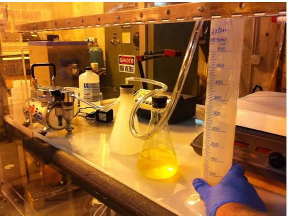
wash solution (now devoid of iron) as solid SDU precipitate. First, a vacuum transfer
apparatus would be assembled by connecting a vacuum pump to a polypropylene
Erlenmeyer flask with a bit of tubing. The first flask would serve as an overflow flask to
protect the vacuum pump, and it would be connected to a second, capture flask by more
tubing. The second flask would be attached to a dipping tube, which would be dipped
into the clear supernate solution to draw it into the flask. This set up is shown in Figure
3.3.
19
This vacuum apparatus would be used to remove the clear supernate liquid from
the top of the Experiment Three settling test, and, afterward, the solid precipitate would
be filtered from the dregs, leaving a brilliant yellow, partially titrated wash solution, now
containing no iron. This solution would be put in a new beaker and further titrated with
8% NaOH, to a pH of 11-12, to form the solid SDU precipitate. An electronic pH sensor
was to be used to record the pH during this titration, and a reading would be taken at
regular intervals to form a titration curve. After the pH reached about 12, the magnetic
stirrer would be stopped and initial settling observations would be made. After these
observations had been made, the stirrer would be started again, a temperature sensor
would be lowered into the solution, and the hot plate would be turned on. The solution
was then to be heated to 35-40°C, and allowed to stir slowly for two hours, to see if heat
and a digestion period increase particle size and speed precipitate settling. After the two
hour digestion time passed, the hot plate and stirrer would be turned off and Experiment
Five would immediately begin.
Figure 3.4 – Experiments 4 & 5
Titration with NaOH to pH 11-12. Filter out SDU.
Eqn. 3.2 Wash Solution
without iron
Waste: Liquid NaF Solution
20 Experiment Five
The fifth experiment was to be used to observe the settling behavior of the SDU
precipitate formed in Experiment Four. The final solution from the fourth experiment
would be poured into a graduated cylinder and the demarcation between the supernate
liquid and solid precipitate was to be recorded, at regular intervals, as in Experiment
Three.
Experiment Six
Once full separation between the SDU precipitate and the liquid waste had been
achieved, Experiment Six would begin. This experiment would be used to extract the
uranium from the SDU precipitate in the form of a carbonate complex solution. This
would start with a filtering of the solution to separate out the SDU. The liquid filtrate
would be set aside for further testing to measure residual uranium content. The SDU
filter cake and filter paper would be removed from the vacuum filtration system and the
SDU scraped into a beaker. A sodium carbonate/sodium bicarbonate solution would be
made by mixing together 240 mL of saturated NaHCO3 solution and 60 mL of 10%
Na2CO3 solution. The filter paper would be washed into the SDU beaker with a bit of
this solution and the rest would be poured into the beaker as well. The magnetic stir bar
would then be added and the stirrer turned on to thoroughly mix the SDU and carbonate
21
Figure 3.5 – Experiment 6
Experiment Seven
Experiment Seven was designed to precipitate the uranium out of the carbonate
solution and into a UO4 solid. A 50 mL portion of the UCO3 solution would be poured
into a beaker with the stir rod. Two 100 mL burettes would be mounted and positioned
above the beaker, one filled with 100 mL of additional UCO3 solution, and the other
filled with 100 mL of 35% H2O2. A small squeeze bottle would be filled with 20%
HNO3, to be used throughout the experiment. The temperature and pH sensors would be
extended into the beaker and preliminary measurements made. Enough HNO3 would be
gradually added to the uranyl carbonate solution in the beaker until the pH dropped to 3,
and then titration would begin. A slow drip of H2O2 would be started, and when yellow
UO4 crystals began to form in the solution, a slow drip of UCO3 would be started as well.
The pH meter reading would be closely monitored at this point, and the flow rates would
be adjusted, and HNO3 would be added, a little at a time, to hold the pH of the solution at
4. The precipitation would be continued until all of the UCO3 had been used, pausing to
refill burettes as needed. Once all of the UCO3 had been added the burettes would be
removed and the final pH and volumes recorded. The mixture would stir slowly
overnight, to allow for a complete reaction and crystal growth.
Dissolve in and mix with sodium carbonate/bicarbonat
e solution for uranyl carbonate extraction.
Eqn. 3.3 Solid
SDU
Uranyl Carbonate in
22
Figure 3.6 – Experiment 7
Experiment Eight
Experiment Eight was a settling test for the UO4 precipitate produced in
Experiment Seven. After being allowed to stir all night, the mixture from the seventh
experiment would be poured into a graduated cylinder and observed as in the third and
fifth experiments. After full settling had taken place, the solution would be filtered,
separating the UO4 precipitate from the NaNO3 solution filtrate. The liquid filtrate was
stored for further analysis and the solids were set aside for drying and subsequent
analysis.
Both the liquid and solids were analyzed by on a Thermo Scientific Element II
high –resolution inductively coupled plasma mass spectrometer (ICP-MS). The liquids
were analyzed for uranium content in parts per million (ppm) and the solids were
analyzed for Na and Fe contamination in ppm. Each liquid sample was collected and
diluted by a factor of 100, and each solid sample was made by dissolving about 1 mg of
solid UO4 in 100 mL of 5% HNO3 solution. The ICP-MS was calibrated by analyzing a
blank rinse of 2% distilled nitric acid five times, then, each sample was run through the
machine and the data was collected. The concentrations of the contaminants in question
Titration with H2O2
and HNO3. Filter out
UO4 precipitate.
Eqns. 3.4 & 3.5 Uranyl
Carbonate in Solution
Waste: Liquid Filtrate
Final, Solid UO4
23
were calculated based on a linear regression. Special thanks must be given to Elizabeth
Bair and the Center for Elemental Mass Spectrometry at the University of South Carolina
for running these tests and analyzing the data.
Experiment Nine
The ninth and final experiment was designed to evaluate a process for the removal
of fluoride from the NaF solution generated in Experiment Four and filtered in
Experiment Five. This was to be accomplished by filling a Sentry RC-100 column with
calcite granules and capping it. The bottom end would be attached to the vacuum
apparatus and the top connected to a length of tubing which was to be used to draw the
NaF solution into the column.
The NaF solution would be poured in a glass beaker, placed on the hot plate, and
heated to about 70°C, then enough 20% HNO3 would be added to drop the pH to about 5.
This heated, pH-modified solution would be drawn out of the beaker and run through the
column slowly—in increments of about 5mL each—until it had all passed through the
column. The NaF solution, at a pH of about 5, reacts with the calcite to form sodium
carbonate and calcium fluoride according to the reaction noted in Equation 3.6.
(3.6)
Should multiple passes be required, the solution exiting the column would be
collected and have its pH checked and modified as necessary. It would then be heated
and run through the column again.
These nine experiments came together into five test series. The first test series
24
process from experiment two through experiment eight. The results of the second test
series led to the development of modifications to the process, which had to be tested, and
an auxiliary test was devised to do this using the combination SDU/Fe(OH)3 precipitate
in NaF solution that was the product of the first test series. This modified process was
altered to forego the partial precipitation step in experiments two and three, and separated
the iron from the wash solution during the carbonate extraction in experiment six, also
changing the carbonate extraction process to use only water and NaHCO3. This test
series was named “Auxiliary Tests on First Test Series SDU.” The modified process is
shown in Figure 3.3.
Figure 3.7 – Modified Recovery Process
Titration with H2O2
and HNO3. Filter
out UO4 precipitate.
Eqns. 3.4 & 3.5 Filter Fe(OH)3
precipitate
Titration with NaOH to pH 11-12.
Filter out precipitate. Eqns. 3.1 & 3.2
Dissolve in and mix with sodium bicarbonate solution for uranyl
25
The third and fourth test series ran through the potassium-analogous process,
going from experiments two through eight, as modified in Figure 3.3, using KOH in
place of NaOH, KHCO3 in place of NaHCO3, and K2CO3 in place of Na2CO3. The fifth
and final test series was used as a verification run for the modified recovery process,
going through the entire procedure from the second to ninth experiments, again, as
26
C
HAPTER4:
R
ESULTS ANDD
ISCUSSIONFirst Test Series
The first test series was used to develop a precipitation curve for the initial
reagents. A UO2F2 solution was prepared by dissolving 16 g of the UO2F2 powder mix
into 100 mL of water, and this mixture was titrated with 24 wt% NaOH solution. A
magnetically stirred polyethylene beaker was the reaction container and the NaOH
solution was dispensed as droplets from a 100 mL burette positioned over the beaker.
The pH of the mixture was periodically measured with p-Hydrion paper strips as the
titration progressed, at room temperature. Table 4.1 following depicts the results of the
titration.
Table 4.1 – First Test Series, SDU Precipitation
NaOH added (total mL) pH Comments 0 1.0 Solution light green color 1.8 3.0 Local precipitation, re-dissolved
2.6 3.5
4.6 5.5 Precipitation persisting more 5.6 5.5 Tan/yellow precipitate forming 7.5 6.5 Precipitating heavily
9.2 7.0
12.6 8.0
17.8 10.0 Precipitation complete
27
The data are displayed graphically in Figure 4.1 below. Test photos are also
shown in Figure 4.2 and 4.3.
Figure 4.1 – Graph of First Test Series, SDU Precipitation pH Curve, pH v. Volume NaOH Added (mL)
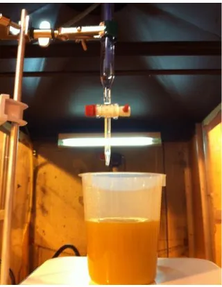
Figure 4.2 – Powdered UO2F2 dosed with 3wt% FeF3, and
the powder dissolved in water
0 2 4 6 8 10 12 14
0 5 10 15 20 25
pH
Volume NaOH Added (mL)
28
Figure 4.3 – Titration with NaOH
One item of test observation was that the magnetic mixing system was having
difficulty dispersing first additions of NaOH with the result that localized precipitation
formations took several seconds to re-dissolve and stabilize in the solution. As a result, a
decision was made to dilute the NaOH solution with water from 24% to 8% on
subsequent test series, in order to better control the uniformity of the precipitations.
After the pH of the slurry of precipitated SDU/Fe(OH)3 reached 12.0, it was
transferred to a storage bottle and left overnight to settle. The next morning the solids
had settled to one-third of the original slurry volume, with the remaining two-thirds of the
volume consisting of a clear supernate liquid. The settled mixture was held for additional
testing, described later in this chapter, in the section “Auxiliary Tests on First Test Series
29
Figure 4.4 – First Test Series SDU after overnight settling
Second Test Series
The second test series started with 50 g of the UO2F2 powder dissolved in 300 mL
of water. The precipitation setup was the same as it was for the first test series, except
8% NaOH solution was loaded into the titration burette. The purpose of the first step of
this series was to evaluate a partial precipitation technique for separating the iron from
the uranium in the mixture. In theory, the FeF3 solid and any dissolved Fewould be
immediately converted to Fe(OH)3 solid at the first addition of NaOH and would remain
insoluble at a pH lower than where the uranium would begin to precipitate as SDU. A
physical separation of the iron from the uranium at pH of about 4.5 was thought to be
possible. As the titration began, a rust colored precipitate soon formed, so it looked as if
the reaction was following the prediction. As the titration reaction progressed, however,
30
the pH measured 4.5. The titration was stopped and the mixture was transferred to a
graduated cylinder for a settling test.
The settling test data are shown in Table 4.2 following. The starting volume of
the mixture was 315 mL on the graduated cylinder.
Table 4.2 – Second Test Series, Partial Precipitation of Iron Sediment Settling
Settling Time (min)
Volume of Supernate Liquid
(mL)
Volume of Slurry
(mL) Comments
10 305 10 Murky supernate
20 307.5 7.5
30 307.5 7.5 Some clearing
40 307.5 7.5 Clear
50 307.5 7.5
60 307.5 7.5
80 307.5 7.5
100 307.5 7.5
120 307.5 7.5
Overnight 307.5 7.5 Clear*
*Had a slight haze to about 15 mL above slurry
The result of the settling was a very rapid separation to a fixed fraction of solids
and liquid that did not change even with extended settling. A yellowish caste remained in
the precipitate indicating some SDU had precipitated with the iron.
31
The purpose of the next steps of this series was to filter the mixture to separate the
iron precipitate and then set up the filtrate to complete the precipitation of SDU.
Figure 4.6 – Siphoning off supernate liquid before filtering out Fe(OH)3 solids
The filtration yielded 265 mL of filtrate which was put into a beaker for titration
with additional 8% NaOH solution. The filtrate volume had been reduced by the solids
removal and some evaporation losses during the previous overnight settling test. The
Hanna electrical pH meter was set up for the first time and its probe was submerged in
the beaker of filtrate before the titration began. It took about 20 minutes for the pH meter
to stabilize at a starting reading of 5.05 (versus pH 4.50 by p-Hydrion paper measurement
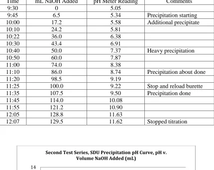
at the end of the previous day). Table 4.3 and Figure 4.7 show the SDU precipitation
32 Table 4.3 – Second Test Series, SDU Precipitation
Time mL NaOH Added pH Meter Reading Comments
9:30 0 5.05
9:45 6.5 5.34 Precipitation starting 10:00 17.2 5.58 Additional precipitate
10:10 24.2 5.81
10:22 36.0 6.38
10:30 43.4 6.91
10:40 50.0 7.37 Heavy precipitation
10:50 60.0 7.87
11:00 74.0 8.38
11:10 86.0 8.74 Precipitation about done
11:20 98.5 9.19
11:25 100.0 9.22 Stop and reload burette 11:35 107.5 9.50 Precipitation done
11:45 114.0 10.08
11:55 121.2 10.90
12:05 128.8 11.63
12:07 129.5 11.62 Stopped titration
Figure 4.7 – Graph of Second Test Series, SDU Precipitation pH Curve, pH v. Volume NaOH Added (mL)
0 2 4 6 8 10 12 14
0 20 40 60 80 100 120 140
pH
Volume NaOH Added (mL)
33
Figure 4.8 – Titration set-up
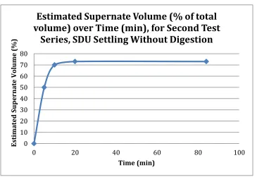
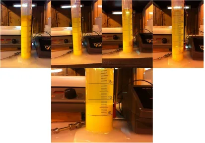
The magnetic stirring was stopped to install the temperature probe into the beaker.
Just after the stirring stopped, preliminary observations of the settling characteristics were
noted. The estimated supernate volume in the beaker for each time period is shown in
Table 4.4 below, as a prior-to-digestion settling data set.
Table 4.4 – Second Test Series, SDU Settling, No Digestion Period
Time Estimated Supernate Volume (% of total volume)
12:11 0
12:16 50
12:21 70
12:31 73
13:35 73
These data indicated that even without a heated digestion period to promote
particle size growth, the solids settled into the bottom 27% of the beaker within 20
34
Figure 4.9 – SDU settling, no digestion period
Figure 4.10 – Graph of the Estimated Supernate Volume (%) over Time (min) for Second Test Series, SDU Settling, Without a Digestion Period
At 13:40 the magnetic stirrer was re-started and the heating plate under the beaker
was turned on. The temperature of the slurry was elevated to 35-40°C and held there for
about 2 hours to give the mixture a digestion period. Next, the mixture was poured into a
graduated cylinder along with about 5 mL of water used to rinse out the beaker. The
settling test data for the 400 mL of digested slurry follows in Table 4.5.
0 10 20 30 40 50 60 70 80
0 20 40 60 80 100
Est ima ted S u p er na te V olu me (%) Time (min)
Estimated Supernate Volume (% of total
volume) over Time (min), for Second Test
35
Table 4.5 – Second Test Series, SDU Settling, With Digestion Period
Time Supernate Volume (mL) Slurry Volume (mL)
15:45 0 400
15:50 160 240
15:55 240 160
16:00 275 125
16:05 290 110
16:10 300 100
16:15 310 90
16:20 315 85
16:25 315 85
16:30 315 85
Overnight 317.5 82.5
An interesting observation of the data in Table 4.4 and Table 4.5 shows that a
twenty minute settling gives almost exactly the same sediment volume fraction (about
27%), indicating that heated digestion at about 40°C does not improve settling rates of
the slurry sediment—at least not in the early stages of the settling. A graph display of the
36
Figure 4.11 – Graph of the Supernate Volume (mL) over Time (min) for Second Test Series, SDU Settling, With 2 hour Digestion Period
Figure 4.12 – Second Test Series, SDU settling after 2 hour digestion
0 50 100 150 200 250 300 350
0 10 20 30 40 50
Su
p
er
na
te
V
olu
me (mL
)
Time (min)
37
The next step in this series was used to convert the solid SDU into a solution of
uranyl carbonate and further remove any carryover iron contamination. This was
accomplished by mixing the SDU with a solution of Na2CO3 and/or NaHCO3 at a pH of
about 10.1. The two carbonate reagents used were 10% Na2CO3, which measured at a pH
of 11.84, and saturated NaHCO3, which measured at a pH of 8.27.
The settled mixture from the graduated cylinder in the previous test was filtered to
separate the SDU from the NaF solution present at that stage of the process. The SDU
filter cake was recovered from the filter paper and put into a beaker with 300 mL of 10%
Na2CO3 solution. This mixture was stirred for 45 minutes to break up the SDU filter
cake, then heated to 35°C for one hour while stirring. The mixture was then poured into
a storage bottle and allowed to settle overnight. The next day the mixture had separated
into about two-thirds clear yellow solution and one-third tan colored sediment. The tan
sediment color (instead of a bright yellow) indicated that some iron was still present, and
because of the sizeable amount of sediment, not all of the SDU had been converted into
soluble uranyl carbonate complex. The pH of the mixture was also high, at 11.83.
38
Figure 4.14 – SDU Filter Cake in Beaker, Sodium Carbonate/Bicarbonate mixture (pH=10), Slurry of SDU and 300 mL of 10% Na2CO3 solution
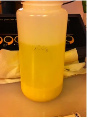
Figure 4.15 – Uranyl Carbonate Solution after overnight settling. Yellow sediment
at the bottom shows that not all of the SDU has been converted.
These results led to a decision to re-treat the mixture with additional carbonate
this time using the 8.27 pH, NaHCO3 solution as the carbonate source in order to lower
the pH of the mixture toward the target of 10.1. First, 50 mL of water was added and the
39
Next, 100 mL of the NaHCO3 solution was loaded into a burette and slowly added to the
mixture. The pH decreased to 10.45. Another 100 mL increment was similarly added
and the pH decreased to 10.12. By this time the 600 mL beaker being used was nearly
full, so the mixture was split into two portions with one portion placed into a storage
bottle for an extended settling period and the other portion returned to the beaker for
additional processing.
Addition of another 50 mL of NaHCO3 to the beaker decreased the pH to 9.95, at
which point no further NaHCO3 was added. The mixture was then heated to 40°C and
poured into a storage bottle. The final pH of the heated mixture was 9.84. After
overnight settling both halves of the mixture had light brown flocculent precipitates with
the volume of precipitate in the heated portion about half the volume in the unheated
portion.
Figure 4.16 – Final UCO3 Products. Clear, yellow uranyl carbonate
40
The continuing presence of the light brown flocculent precipitate indicated that
there was some iron carryover from the earlier pH 4.5 separation step. That, coupled
with the indication that some uranium also precipitated around the pH 4.5 region, pointed
to a precipitation overlap, and suggested that the anticipated clean separation of the two
elements at that condition does not occur. With that being the case, a decision was made
to modify the process to completely precipitate the iron and uranium together at pH 11 –
12, then use the carbonate extraction of the uranium step to separate the two elements.
The purpose of the next test in the second series was to separate the uranium from
the solution of residual sodium compounds. The technique was to precipitate the
uranium as uranyl peroxide, perform a settling test on the peroxide crystals, and then
physically separate the peroxide crystals from the solution mixture of sodium
compounds.
To begin, the first half of the sodium uranyl carbonate solution produced in the
previous test was filtered to remove the iron precipitate remnant. A 50 mL portion of the
filtrate (pH 10) was then put in a beaker to serve as the initiation solution. A total of 25
mL of 20% nitric acid was slowly added to the carbonate until the pH was reduced to 2.0.
Bubbles of CO2 formed and dissipated as the acid reacted with the carbonate. One
burette was filled with 100 mL of 35% H2O2 and another burette was filled with 100 mL
of the carbonate filtrate. Both burettes were mounted above the beaker of starter solution.
A 125 mL squeeze bottle of 20% nitric acid was on standby.
A slow drip of H2O2 was started and immediately a pale yellow (almost white)
precipitate began forming in the starter solution. Next a drip of the carbonate solution
41
when it reached 7.0, nitric acid was added from the squeeze bottle to bring it back down.
The two burette drips and intermittent squirts of nitric acid were continued with frequent
pH checks attempting to hold the pH in the desired 3.5 – 4.5 range during the reaction.
At the beginning there were both high and low excursions out of the desired pH range as
the flows were juggled, but as experience developed, better pH control resulted. The
additions continued until all of the carbonate solution had been used up. The final tally
of inputs was: 230 mL carbonate solution, 35.6 mL 35% H2O2, and 95 mL 20% HNO3.
The mixture was stirred while heated to 45°C for 1.5 hours, then the heat was turned off
and the mixture was left stirring slowly for 72 hours, to allow the peroxide precipitation
to complete. The pH after the heating had fallen to 3.0, evidence of a continuing
peroxide precipitation reaction.
42
After the 72-hour stirring period, the pH had fallen further to 1.5, so some extra
Na2CO3/NaHCO3 mix was added to bring the pH back up to 4.0. During the 72-hour
period, there had also been a substantial evaporation loss from the beaker such that only
195 mL remained of what had started out as 360 mL. The mixture was poured into a
graduated cylinder for a settling test, which test data can be found in Table 4.6.
Table 4.6 – Second Test Series, First Half, UO4 Settling Test
Time (min) Supernate Volume (mL) Slurry Volume (mL)
0 0 195
10 5 190
20 5 190
30 10 185
60 15 180
80 20 175
100 22 173
120 25 170
2 days 42 153
Figure 4.18 – Graph of Supernate Volume (mL) over Time (min) for Second Test Series, First Half, UO4 Settling
0 5 10 15 20 25 30
0 20 40 60 80 100 120 140
Su p er na te V olu me (mL ) Time (min)
43
Figure 4.19 – Settling of Second Test Series, First Half, UO4
The settling data indicated that the peroxide particle size was very small and that
separation may be quite difficult. This was not the case, however, as the subsequent
filtration required only 23 minutes. The peroxide crystals were scraped off the filter
paper and placed in an open container in the process hood to air dry. The dried crystals
were placed in a tared sample bottle, and had a net weight of 30.24 g UO4·nH2O. The
filtrate was a clear solution and a portion of it was also placed in a sample bottle for
subsequent analyses.
Figure 4.20 – Filtration of Second Test Series, First Half, UO4. From left to right:
44
The second half of the second series carbonate extract solution was then filtered
to remove the trace of Fe(OH) 3 solid and was transferred to a beaker. The solution was
precipitated with hydrogen peroxide using the same burette setup and titration technique
described previously for the first half to completely precipitate the UO4 from the solution.
The total reagents used were 394 mL carbonate solution, 65.6 mL 35% H2O2, and 156
mL 20% HNO3. The final slurry was put into a graduated cylinder for a settling test with
the results in Table 4.7, below.
Table 4.7 – Second Test Series, Second Half, UO4 Settling Test
Time (min) Supernate Volume (mL) Slurry Volume (mL)
0 0 500
10 452 48
20 460 40
30 460 40
40 470 30
50 470 30
60 470 30
The settling data showed very rapid initial settling and a very complete separation
of 6% slurry and 94% supernate liquid, after 40 minutes. The mixture was then filtered,
along with the remaining slurry that would not fit into the settling test cylinder and the
UO4 cake was air dried for one week. The air-dried cake weighed 27.82 g.
Auxiliary Tests on First Test Series SDU
An auxiliary series of processing was carried out using the SDU/Fe(OH)3
co-precipitate slurry made from the first test series. The purpose of these tests was to
45
done. Since an iron separation on this slurry had not been attempted, it was ideal to use
it to test the concept of making the iron separation at the carbonate extraction step rather
than at the pH 4.5 partial precipitation step used in the Series 2 sequence. Also, since the
Na2CO3/NaHCO3 mixture used in the Series 2 carbonate extraction yielded such a high
final pH (11.84), it was decided to use only NaHCO3 (pH 8.27) as the extractant in the
auxiliary test. Processing at room temperature (no heating) was a third variant added to
the test technique.
The SDU/FeOH3 slurry from the Series 1 precipitation was filtered and the solids
were scraped off the filter paper into a beaker. A 50 mL allotment of water was used to
help wash off the filter paper, and was added to the beaker and stirred to re-slurry the
SDU/FeOH3 solids. The pH of the mixture was 7.6.
A burette was filled with 100 mL of the saturated NaHCO3 solution and a drip
was started, adding NaHCO3 solution to the SDU/FeOH3 slurry. The beaker was not
heated during this test. The pH measured 7.5 after 50 mL of the carbonate solution was
added and 7.7 after 100 mL was added. Addition of carbonate solution was halted at this
point and the mixture was put into a storage bottle and left to settle. After settling, the
solids had almost completely dissolved leaving a bright yellow solution over a thin,
dark-brown sediment layer.
This mixture was filtered to remove the dark-brown iron sediment, and 50 mL of
46
Figure 4.21 – Uranyl Carbonate Solution prepared from First Test Series SDU and NaHCO3, then filtered. This is the 50mL put into a
small container that served as a starter solution.
A burette was filled with 100 mL of the filtrate, and was mounted above the small
starter solution container, along with a second burette containing 35% H2O2. To begin
the uranyl peroxide precipitation, 18.4 mL of 20% HNO3 plus 1.6 mL of 35% H2O2, plus
an additional 20 mL of the filtrate were added to the container, at which point the mixture
was transferred to a 600 mL beaker. Additional carbonate, acid and peroxide were
slowly added in proportions to keep the pH in the 3.0 – 4.0 range. Once again the beaker
was not heated. The tally of reagents at the end of the precipitation was 194 mL
carbonate solution, 32.1 mL 35% H2O2, and 27.3 mL 20% HNO3. The final pH was 3.5.
The mixture was poured into a graduated cylinder for a settling test, with data shown in
Table 4.8, below.
Table 4.8 – First Test Series, Auxiliary Testing, UO4 Settling
Time (min) Supernate Volume (mL) Slurry Volume (mL)
0 0 235
10 10 225
47
30 25 210
40 40 195
50 57 178
60 85 150
80 97 138
100 105 130
120 110 125
2 days 155 80
Figure 4.22 – Graph of Supernate Volume (mL) over Time (min) for First Test Series, Auxiliary Testing, UO4 Settling
Figure 4.23 – First Test Series, Auxiliary Testing, UO4 Settling
0 20 40 60 80 100 120
0 20 40 60 80 100 120 140
Su
p
er
na
te
V
olu
me (mL
)
Time (min)