UTFM – a Next Generation Language and Tool for Feature
Modeling
by
Vincent Weber, BSc
Thesis
Presented to the Faculty of Electrical Engineering, Mathematics and Computer Science of
the University of Twente
in Partial Fulfillment
of the Requirements
for the Degree of
MASTER OF SCIENCE
University of Twente
Copyright
by
Vincent Weber
The Supervising Committee for Vincent Weber
certifies that this is the approved version of the following thesis:
UTFM – a Next Generation Language and Tool for Feature
Modeling
Committee:
Dr. Pim van den Broek, Supervisor
Prof. dr. Mehmet Aksit
Acknowledgments
Before we delve into the world of feature modeling, there is the moment to reflex and
appreciate the people that made my work, this thesis, a masters project, possible. As one
will see in the thesis, structure and hierarchy are key, therefore I would like to begin with the
persons that had a direct influence on my results.
First, I’d like to thank Mehmet for introducing me to variability and feature modeling
through his courses, and thereafter helping me find a research position abroad. Within six
week I knew where I was heading, mainly due to the contacts he put me in touch with.
Secondly, thank you Don! For being the host for my research internship at the Computer
Science department of the UT at Austin (TX). From the start I have felt welcome and I am
grateful for the freedom that has been given for my research. When I needed guidance or
feedback there was always some free space in his agenda. It were eight pleasant months
working at his office, during which I’ve learned so much. Last, I’d like to thank Pim for
all his efforts to push me to get the best results, furthermore correcting (and parsing, and
typechecking) my thesis to the smallest detail. Without, the result would not have been the
same.
The University of Texas at Austin, and the city itself, has made a great impact. I
would like to thank the institute, with its staff and students for the wonderful experience,
through which I bleed a little burned orange nowadays. Hook ’em!
Besides during my research, I have always been supported by family and friends.
accomplishments or needed moral support to continue. With this thesis my time as a student
ends, and for this unforgettable time I’d like to thank my friends from my yearclub, my
fraternity Ius Sanctus and my house Kroegzicht, and all other close friends.
VINCENTWEBER
UTFM – a Next Generation Language and Tool for Feature
Modeling
Vincent Weber, MSc
University of Twente, 2014
Supervisor: Dr. Pim van den Broek
An important aspect ofvariability managementinsoftware product linesis throughfeature
modeling, in which relations between different features are specified. Over the year
exten-sions of classical feature models have been proposed, however never properly combined and
implemented. We propose the next generation feature modeling language:UTFM
(Univer-sity of Twente/Univer(Univer-sity of Texas Feature Models), that entail generalized classical feature
models with instance and group cardinalities, extended withfeature replication,feature
attributes(arithmetic, boolean and string attributes) andcomplex cross-tree constraints.
The language explicitly separatestype declarations, defining feature types,
hierarchi-cal relations, attributes and constraints, from model configurations.Configurationsconsist
of instance declarations of feature types and value assignments to feature attributes. We
explain our interpretation of the semantics ofnested feature replication. We introduce a
in cross-tree constraints, as well as how this leads to a language that has similar behavior
as anattribute grammar. Along we propose the automated analysis operationconstraint
propagation. An algorithm for propagating determinable values to instances and attributes
based on provided configurations. The propagation algorithm is supported by anunfolding
process that makes undecided instances in a configuration explicit.
To validate the proposed language and analysis operations an proof-of-concept tool
is implemented. In order to check satisfiability of configurations the tool translates UTFM
models to Z3 decision problems (an off-the-shelf SMT theorem prover). To translate the
models to the decision problems an UTFM to Z3 mapping is described for the various
semantics. Furthermore two examples are provided that show case the capabilities of UTFM.
As a whole, the UTFM language and tool, set a step forward to converge feature
mod-els with advanced semantics towards standards, furthermore to enrich variability modeling
Contents
Acknowledgments iv
Abstract vi
List of Figures xi
Chapter 1 Introduction 1
1.1 Next generation feature modeling . . . 2
1.2 Motivation . . . 3
1.3 Problem Statement . . . 3
1.4 Research Goals . . . 4
1.5 Methodology . . . 5
1.6 Contributions . . . 5
1.7 Outline of Thesis . . . 6
Chapter 2 Classical Feature Models 7 2.1 Classical Semantics . . . 7
2.2 UTFM Type Declarations and Configurations . . . 10
2.2.1 Type Declaration . . . 11
2.2.2 Constraint Language . . . 12
2.3 Mapping to UTFM . . . 18
2.4 Automated Analysis with Z3 . . . 19
2.4.1 Translating to Z3 . . . 21
2.4.2 Automated Analysis . . . 24
Chapter 3 Feature Replication 31 3.1 Replication of Features . . . 31
3.2 Multiple Instances in UTFM . . . 33
3.2.1 Type Declaration . . . 33
3.2.2 Constraint Language . . . 34
3.2.3 Configuration . . . 36
3.3 Automated Analysis with Z3 . . . 38
3.3.1 Translating to Z3 . . . 38
3.3.2 Constraint Propagation . . . 39
Chapter 4 Attributed Feature Models 41 4.1 Classical Attributed Feature Models . . . 41
4.2 Attributes in UTFM . . . 43
4.2.1 Type Declaration Extensions for Attributes . . . 43
4.2.2 Constraint Language Extensions for Attributes . . . 44
4.2.3 Configurations with Attributes . . . 51
4.2.4 Mapping Classical Attributed Feature Models to UFTM . . . 52
4.3 Automated Analysis with Z3 . . . 53
4.3.1 Mapping to Z3 . . . 53
4.3.2 Constraint Propagation . . . 55
Chapter 5 UTFM Tool 57 5.1 Functionality and Tool usage . . . 57
Chapter 6 Examples 65
6.1 Mobile Device Interface SPL . . . 65
6.1.1 Entities . . . 66
6.1.2 Navigation . . . 67
6.1.3 Window Size . . . 69
6.1.4 Stylesheet . . . 71
6.1.5 Tool execution . . . 73
6.2 Subsea Oil Production SPL . . . 73
Chapter 7 Related Work 78 Chapter 8 Conclusion and Future Work 82 8.1 Results and Conclusion . . . 82
8.2 Future Work . . . 84
8.2.1 Reuse and Modularization . . . 84
8.2.2 Optimization . . . 84
8.2.3 Integer Programming . . . 85
8.2.4 Front-end . . . 85
Appendix A Context-free Grammars UTFM 87 A.1 Type declaration . . . 88
A.2 Configuration . . . 89
A.3 Product . . . 90
A.4 Constraint Language . . . 91
Appendix B Tool Execution Options 93
List of Figures
1.1 Classical feature model of a Car [7]. . . 2
2.1 Classical Feature Models . . . 10
2.2 Feature model type declaration of the GraphLibrary example (Figure 2.1). . 13
2.3 Context-free grammar or UTFM constraint language for classical models. . 14
2.4 Simple example ofexistsoperations. . . 14
2.5 More complicated constraints. . . 15
2.6 FMTD of Figure 2.2. . . 16
2.7 Configuration of Figure 2.6 in UTFM. . . 17
2.8 Graphical representation of Figure 2.7. . . 17
2.9 Very basic Z3 satisfiability problem. . . 20
2.10 Cardinalityfunction. . . 20
2.11 Instance and instance cardinality in Z3. . . 22
2.12 Group and group cardinality in Z3. . . 22
2.13 Cross-tree constraint in Z3. . . 23
2.14 Automated analysis process. . . 24
2.15 Configuration of Figure 2.7. . . 26
2.16 Propagated configuration of Figure 2.15. . . 26
2.17 Unfolded configuration of Figure 2.16. . . 29
2.19 Product specification of Figure 2.18. . . 30
3.1 Feature model with replication from [15]. . . 32
3.2 Classification of different cardinality interpretations. . . 34
3.3 Foralloperation examples. . . 36
3.4 Type declarations for Figure 3.3. . . 36
3.5 Multiple configurations of Figure 3.3b. . . 37
3.6 Z3 translation of anexistsoperation on a non singular feature type. . . 38
3.7 Z3 translation of cross-tree constraint of Figure 3.3b using Figure 3.5d . . . 39
3.8 . . . 40
4.1 Attributed feature model by Benavides et al.[7]. . . 42
4.2 Part of the graphical FTMD representation of Service feature model (Fig-ure 4.1). . . 45
4.3 Part of the FMTD of Service feature model (Figure 4.1). . . 45
4.4 Constraint language grammar of Figure 2.3 extended to support attributes. . 49
4.5 Substitution example. . . 51
4.6 Example configuration of Figure 4.3. . . 52
4.7 Z3 arithmetic attribute. . . 53
4.8 Z3 boolean attribute. . . 54
4.9 Z3 arithmetic constraint. . . 54
4.10 Z3 maximum and minimum functions. . . 55
4.11 Z3 maximum and average example. . . 55
4.12 Configuration after constraint propagation of Figure 4.6. . . 56
5.1 Overview on analysis processes in the tool . . . 59
5.2 Validating type declarations. . . 59
5.3 Validating configurations. . . 60
5.5 Translating configurations to products. . . 61
5.6 Propagating constraints for configurations. . . 62
5.7 Unfolding and propagating constraints for configurations. . . 62
5.8 Internal structure of the UTFM tool . . . 63
6.1 Window FMTD. . . 68
6.2 . . . 68
6.3 Window navigation constraints. . . 69
6.4 Possible scrollability constraints. . . 69
6.5 Window size constraints. . . 70
6.6 Complex constraints to constraint the window size. . . 70
6.7 . . . 71
6.8 Stylesheet configurations of Figure 6.7a. . . 72
6.9 Stylesheet configuration of Figure 6.7b. . . 73
6.10 The subsea oil production system fragment from [6]. . . 74
6.11 UTFM representation of the subsea oil production SPL fragment. . . 74
6.12 FMTD translation of SimPL fragment in Figure 6.11. . . 75
6.13 Configuration of SimPL fragment Figure 6.10. . . 77
6.14 Configuration translation of SimPL configuration in Figure 6.13. . . 77
A.1 Context-free grammar of FMTD’s. . . 88
A.2 Context-free grammar of Configurations. . . 89
A.3 Context-free grammar of Products. . . 90
Chapter 1
Introduction
Producing individual tailored software products efficiently is know in software
engineer-ing assoftware product lines(SPL) orsoftware product families. Customizing reusable
artifacts is the key, where the focus is onfeatures functionalities that are shared among
members. Thesoftware product line engineeringparadigm models and manages variability,
i.e. commonalities and differences in the applications in terms of requirements, architecture,
components and test artifacts [27].
Kang et al. [23] introduced feature modeling in their Feature Oriented Domain
Analysis (FODA) publication. Feature models(FM) represent the relations between the
features of a product line in a hierarchical way. Legal combinations of features are in 1:1
correspondence with products of a product line, thereby describing an entire family of
products in a single model. Figure 1.1, published by Benavides et al. [7], illustrates a basic
example of a feature model describing various mobile phones, with variability in screens
and media features. As explained in the legend of the figure, certain features are mandatory,
while others are optional, and some features are dependent of another, and some are mutual
exclusive. By selecting features a configuration is made of the feature model.
The information in a FM can be used in various ways, and the process of extracting
started adding extra semantics to feature models such as cardinalities, feature attributes and
allow feature replication (cloning). These new semantics have not matured to the point that
they also regarded as classical semantics.
An attempt has been made recently to unite many concepts for a the next generation
feature models in Common Variability Language [], however unfortunately this proposal has
been stranded (i.e. discontinued as the basis of an OMG standard). This attempt shows us that
there is interest in uniting the parallel researches to work towards more standards in feature
modeling. In our work we attempt to do provide a full implementation and description of a
next generation feature modeling language,University Twente/University of Texas Feature
Modeling(UTFM).
1.2
Motivation
To date much is unclear on how to interpret the advanced semantics of feature models and
how they should be properly integrated with each other. Better insight in the possibilities that
richer semantics bring leads to a better understanding of the effects of richer semantics on
the structure of a feature modeling language. The implementation of languages could lead to
new standards in feature modeling, which would make it more likely that better tools will
be developed as the research field becomes less experimental. In order to proceed in such a
direction we propose the next generation feature modeling language UTFM and implement
a proof-of-concept tool for our proposed language and analysis operations.
1.3
Problem Statement
Defining a feature modeling language with advanced functionality poses two main challenges.
The first challenge comes forth from the absence of standards in feature modeling, the second
from the interference between the different advanced semantics.
publications has branched and made the research field more fragmented. Due to the different
publications on additional semantics for classical feature modeling it is unclear: 1. to which
extend is it possible to add additional functionality; 2. what should this language look like;
3. to what kind of satisfiability porblem should a feature model be translated; 4. what are
practical examples that can be used to showcase the functionality of the language. The
different interpretations of feature attributes and feature replication have been published
using different syntax, makes it hard to compare the proposals. Besides the lack of consensus
on what feature modeling language with advanced semantics should entail the translation
from model to satisfiability problem adds more complexity to the equation. The spectrum
of interpretations has also not lead to model examples that are used as standard examples
through different publications which would make comparison of interpretations easier.
The versatility has not lead to a feature modeling language that implements advanced
feature modeling functionality in a single language. Attempts to unify previous proposals
of advanced semantics have not been finalized. The absence of successful proposals for
advanced feature modeling languages leads to the suggestion that the combinations of
attribute and replication semantics to implementations challenges. UTFM is required to
integrate these semantics without interfering with each other. The challenge designing UTFM
is to sort out these differences and make design decisions and implement a proof-of-concept
tool accordingly.
1.4
Research Goals
The main goal of our work is to develop a full implementation of the feature modeling
language UTFM that bundles previously proposed advanced feature modeling semantics
besides the classical semantics. Our point of reference is classical feature modeling along
with advanced semantical concepts that have been published. In order to incrementally
advance in going from our point of reference to the proposed research goal we define the
1. define the semantics and syntax of UTFM;
2. implement a parser and automated analysis tool for the UTFM language;
3. provide examples that demonstrates the capabilities of the functionality of the
lan-guage.
1.5
Methodology
First through a process of trail-and-error an overview is made on the semantics of the designed
language, how the different advanced semantics of feature modeling can be combined without
interfering with other semantics. Through this process a series of design decisions are made
which lead to the structure of UTFM. By defining a context-free grammar the syntax of the
language is specified.
Secondly by developing a tool which automates the validation of constructed feature
models in UTFM, and implements automated reasoning operations shows the feasibility of
the previously stated modeling language. Additionally, by performing automated reasoning,
it demonstrates that current off-the-shelf theorem provers are capable of analysing advanced
semantics of feature models.
For the third sub-goal examples demonstrate possible usage of UTFM language
combining advanced feature modeling semantics in a practical problem domain.
1.6
Contributions
Within this thesis the feature modeling language UTFM is presented that implements feature
attribute, feature replication and complex cross-tree constraint semantics. For the language a
textual and graphical syntax are provided. Furthermore a tool is implemented that performs
prover Z31.
1.7
Outline of Thesis
Chapter 2 starts of with the introduction to the semantics and syntax of UTFM, which are
described by providing a mapping from classical feature models to the proposed language.
Furthermore it elaborates on the automatic reasoning process: constraint propagating and
the supporting unfolding algorithm.
Chapter 3 discusses how UTFM supports the replication of features and how feature
models can be constraint when more then one instances are present in a product configuration.
Along it is explained how multiple instances, and cardinalities of features are interpreted and
how it impacts automated reasoning.
In Chapter 4 the last semantics of UTFM are explained with the introduction of
feature attributes. It is explained how attributes are declared for features and instances and
how these attributes constraint configurations. This is followed by a description on the
automated analysis of features that have attributes.
The proof-of-concept tool is introduced in Chapter 5. The functionality of tool as
well as how to execute these operations are described. Furthermore the implementation
structure of the tool is elaborated.
Chapter 6 provides examples that showcase the potential of the UTFM language.
Chapter 7, the related work section describes the latest research that is published
with regard to feature modeling with advanced semantics and automated analysis. These
works are placed in context with our proposed language.
Chapter 8 concludes the thesis by providing the final discussion and summary of the
contributions that are made. In the end recommendations are made on the direction of future
research and possible enhancements of UTFM language and tool.
Chapter 2
Classical Feature Models
In this chapter we explain classical feature modeling in UTFM language.
1. We review ideas originally proposed by Kang in 1990 and those added by others
through 2006, that we regard as classical feature modeling;
2. We explain the structure of how models in UTFM are declared and configured;
3. A set of translation rules is given to map classical feature models to UTFM, showing
that UTFM preserves classical capabilities;
4. The theorem prover Z3 is introduced along with rules to translate UTFM specifications
to Z3 specifications. Z3 performs automated reasoning on UTFM feature models;
These topics provide insights into the fundamental concepts of UTFM, which are used in
future chapters to introduce new (or more precise) semantics in UTFM feature models and
automated reasoning.
2.1
Classical Semantics
Feature Models.In 1990, Kang et al. [23] introduced feature models to encode the program
Czarnecki et al. [15] and Batory et al. [4]) to what we now regard today as classical feature
models. These models deal with three central concepts:features,hierarchical structure, and
cross-tree constraints. We describe how classical feature models are interpreted in the past.
Features. A featureis an increment in functionality. A feature model enumerates the
features used in a software product line. Every program in an SPL is identified by a
unique set of features. This set of features is called aconfigurationand each feature in
the set is said to beselected.
Hierarchical Structure. Features are related to each other by a tree structure, starting with
a root feature and descending downward using parent-child relations to produce a
hierarchy. A key rule of configurations is that if a child feature is selected, its parent
feature must also be selected.
The children of a parent form a group relation w.r.t. the parent. There are three
different groups: or,and, andalternativerelations. Anorrelation requires one or
more children to be selected in a configuration. An alternative relation requires
precisely one child to be selected, and anand relation requires all children to be
selected (with the exception of children that are labeled asoptional).
Czarnecki et al. [14] generalized thegroup relationby adding cardinalities, whose
syntax is similar to multiplicities in class diagrams of UML. Acardinalityis an ordered
pair[l..u]of integers, wherel≤u. Valuelis the lower bound on the number of children that must be selected in a group anduis the upper bound, this is called the
group cardinality of a relation. Besides cardinality for group relations, Czarnecki et
al. [15] introduces feature cardinality, to specify the amount of allowed clones of a
feature. Assuming classical feature models do not entail feature replication, there
are onlyoptionalfeatures ([0..1]feature cardinality) andmandatoryfeatures ([1..1]
feature cardinality).
as follows: suppose a parent node hasnchildren, of whichk are optional. Anor
relationship is indicated by the cardinality[1..n], anandrelationship has the cardinality
[(n−k)..n](wheren−kare the mandatory features), and analternativerelationship is
[1..1], where all child features in the group relation have a feature cardinality (defining whether the feature is optional or mandatory).
Cross-Tree Constraints. Not all relationships among features can be expressed as
parent-child. Features that are selected in one branch of a tree may preclude or demand
the selection of features in other branches. Cross-tree constraintsexpress such
re-lationships. At first cross-tree constraints entailedrequiresandexcludespredicates
that related two features. Batory [4] proposed that cross-tree constraints can be
arbi-trary propositional formulas. Some tools today still only allowrequiresandexcludes
constraints, e.g., KConfig [34, 37].
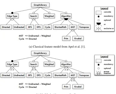
Figure 2.1a illustrates a classical feature model, provided by Apel et al. [1]. This
model uses different group relations and is constrained by two propositional formulas. In
the Figure legend,exclusive orrelations are identical to thealternativerelations described
earlier. Figure 2.1b illustrates the same feature model using group relations and cardinalities.
This figure is not provided by Apel, but created by us.
Configurations.Products of a product line are specified by configurations of a feature model.
We mentioned earlier that a configuration is a subset of features that have been selected.
The configuration represents a product, or products, in which those features are present.
Benavides et al. [7] formalizes it as: there is a set of featuresFand a 2-tuple configuration
(S,R), whereSthe set of selected features,Rthe set of removed features such thatS,R⊆F, andS∩R=∅. In afullorcomplete configurationevery feature of the model is either selected or removed (S∪R=F); it is apartial configurationotherwise (S∪R⊂F). Batory [4] said features wereundecidedwhen features are neither selected or removed. We regard this as
(a) Classical feature model from Apel et al. [1].
(b) Modified with group cardinality.
Figure 2.1: Classical Feature Models
that its selected features satisfy all feature model constraints; the full configuration isinvalid
otherwise. A partial configuration isvalid if it can be configured further (by converting
undecidedfeatures into selected or removed) to produce a valid full configuration. A partial
configuration isinvalidotherwise.
2.2
UTFM Type Declarations and Configurations
Classical feature models and their configurations distinguished (albeit implicitly) between a
feature type declaration (the feature model) and feature type instances (configurations). With
concerns. Thefeature model type declaration (FMTD)of UTFM subsumes (and as we will
see later chapters, goes beyond) the semantics of classical feature models. In the following
sections, we introduce the UTFM constraint language, and then UTFM configurations. We
limit our discussion of UTFM concepts to just describe classical semantics. Therefore we
make assumptions, which in the future we will retract to achieve generality.
2.2.1 Type Declaration
A FMTD specifies the structure and constraints of a UTFM.
Features. A “feature” in a FMTD denotes afeature type; it has no configuration information.
Instances of a feature type are actual features in a product, sometimes calledfeature
replicas. Classical feature models usesingleton feature types: types that have precisely
one instance. (It was for this reason that feature types and feature instances were not
clearly distinguished in classical models).
More generally, each feature type in a FMTD has aninstance cardinalitythat defines
the lower and upper bound on the number of its instances that may be permitted in
a product. Using the cardinality notation defined earlier ([l..u]meanslis a lower bound on the number of instances anduis the upper bound), amandatoryfeature has
the cardinality[1..u]and anoptionalfeature has[0..u].1 In classical models, instance
cardinalities are eithermandatoryoroptional, and under the assumption that there can
only be a single instance of a type, the upper bound is 1.
In classical feature modeling, a featureAmeant “A” is the name of the feature type
and “A” is the name of its sole instance. However in UTFM, with the possibility of
feature replication, this meansA(a non-indexed term) denotes a feature type andAi
(an indexed term) denote theith instance ofA. All instances of a type have unique
names via their index values.2
1When instance cardinality was introduced, it was decided to leave out redundant syntax [14]. For UTFM,
we decided to always express instance and group cardinalities, consistency is valued over conciseness.
2UTFM and the tool do not require theA
Hierarchical Structure. All group relations (and-, or-, alternative-) are replaced by a
general group relation with a[l..u]group cardinality. This means that both feature typesandgroup relations have cardinality specifications in a FMTD. A group relation
is part of the declaration of a parent feature type and is associated with one or more
child feature types.
CrossTree Constraints. Cross-tree constraints expressed in propositional logic, not limited
to elementaryrequiresandexcludesstatements. They are declared within the local
scope of feature types and therefore are no longer regarded as global constraints.
This restriction makes the translation of classical cross-tree constraints to FMTD
more elaborate; the benefits for doing so are explained in later sections. Figure 2.2
illustrates how a constraint belongs to a feature type, annotated with a dashed line to
the owner. The constraint language of UTFM and possible operations are explained in
Section 2.2.2.
Figure 2.2 shows the FMTD representation of the classical feature model of
Fig-ure 2.1b. All group relations have been replaced with group cardinalities and each featFig-ure
type has an instance cardinality. Every instance cardinality is mandatory[1..1]or optional
[0..1]in relation to its parent. Cross-tree constraints are specified in a parallelogram, within the scope of the root feature. Also our notation is similar to that of theCommon Variability
Modeling (CVL)[25] proposal for cross-tree constraints.
2.2.2 Constraint Language
Cross-tree constraints written in UTFM are boolean expressions that are required to hold
within the scope of a feature type. Expressions can either be a propositional formula or a
boolean operation on a feature type. Propositional logic constructs included in the constraint
Figure 2.2: Feature model type declaration of the GraphLibrary example (Figure 2.1).
language are:and,or,implies, andnot. As we will ultimately deal with sets of feature type
instances, we reference instances via operation calls. For now we only introduce a single
boolean operation for types:exists.3 Figure 2.3 states the context-free grammar for UTFM
constraint language for classical feature models. A complete grammar of the constraint
language is provided in Appendix A.4.
Exists(FeatureType) :: Bool. Operationexistsreturns a boolean value indicating if there
exists a selected instance of the specified type: trueif there is at least one selected
instance of the feature type in the configuration, otherwisefalse.4
Let parentPdenote a feature type for which a cross-tree constraint has been defined, and
letCbe a child ofP. The expressionexists(C)defined atPreturnstrueif there is at least one child instanceCfor the parent instance of typePthat is selected in the configuration,
otherwisefalse. If thePinstance has multiple child instances ofCselectedexistsalso returns
true, this is however outside the scope of classical feature models.
As a concrete example, Figure 2.4 declares that each parentPinstance requires at
least oneA childor at least oneB child instance. Constraints on the selection ofChild
3There is also aforalloperation which is introduced later in Chapter 3. At this point,existsandforallare
semantically indistinguishable as feature types have at most one instance.
4UTFM permits types with no instances, or instances with afalseorundecidedselection value. This is
1 < Constraint > ::= < BooleanExpr > ";"
2
3 < BooleanExpr > ::= < B o o l e a n F o r m u l a >
4
5 < B o o l e a n F o r m u l a > ::= < BooleanProp > " and " < BooleanProp >
6 | < BooleanProp > " or " < BooleanProp >
7 | < BooleanProp > " i m p l i e s " < BooleanProp >
8 | " not " < BooleanProp >
9
10 < BooleanProp > ::= < BooleanOp >
11
12 < BooleanOp > ::= " ex ists (" < FeatureRef > ") "
13 | " exi sts (" < FeatureRef > "." < BooleanOp > ") "
14 | " for all (" < FeatureRef > ") "
15 | " for all (" < FeatureRef > "." < BooleanOp > ") "
16
17 < FeatureRef > ::= < String >
Figure 2.3: Context-free grammar or UTFM constraint language for classical models.
instances are defined as constraints at the feature type that has theChildtype in its group
relation.
Figure 2.4: Simple example ofexistsoperations.
Operations on feature types can be nested. Figure 2.2 illustrates a more complicated
constraint (reproduced in Figure 2.5) with nestedexistsoperations. The nested operation
exists(Algorithm.exists(MST))asks if aGraphLibraryinstance has a childAlgorithm
instance that has a childMSTinstance – or more compactly, if theGraphLibraryinstance
has a selected MSTinstance. The explanation of the implicitly-conjoined constraints in
Figure 2.5 is:
are required for the first expression to betrue.
• If an instance ofCycleis selected, it is required that an instance ofDirectedis also
selected.
Figure 2.5: More complicated constraints.
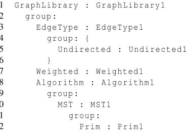
A complete textual specification of Figure 2.2 in the UTFM language is given in
Figure 2.6. In the textual language curly braces are added to avoid ambiguity in the hierarchy
of the model. The mapping of classical feature models to UTFM is explained in the next
section. A context-free grammar for specifing FMTD’s is proved in Appendix A.1.
2.2.3 Configurations
A FMTD represents the set of all legal products for an SPL. Specifying a product is the
process of configuration. A configuration consists of instances of feature types. Every
instance has a selection value that is either true if the feature instance is present in a
configuration, false if the instance is not. The default selection value of an instance is
undecided. If the selection value is set totruewe say the instance isselected, if the selection
value is notundecidedanymore an instance is configured. As the default selection value of
instances isundecided, omitting the specification ofundecidedinstances is allowed.
We require that every feature instance be given a distinct name within a group
relation. As mentioned earlier, instance i for feature typeA has nameAi, although our
language and tool admits non-numbered names. So given feature types parentP, childCand
While by default instances areundecided, we are unable to specify a full
configu-rations, because implicitly there are always unconfigured instances. All configurations in
UTFM are therefore partial configurations. From this point on full configurations will be
called products, a configuration of a FMTD in which only selected instances are specified.
By default everything else in a product is assumedfalse, and is omitted from the product
specification. A similar approach is described in the configuration process for GUIDSL [4].
The configuration presented in Figure 2.7 and Figure 2.8 ispartialandvalid. If we
convert the domain from configuration to product in the example, the figure represents a
validandfullconfiguration, in other words avalidproduct. The context-free grammar for
specifying configurations is provided in Appendix A.2, for products in Appendix A.3. The
difference between these grammars is the removal of the selection value for products.
2.3
Mapping to UTFM
The next step is to show how classical semantics are integrated into the UTFM language
and to provide the mapping from the first to the second. An example of such a translation is
given in original Figure 2.1b to translation Figure 2.2:
Features. Each feature that is declared in a classical feature model is mapped to a feature
type in a FMTD. These feature types are either optional[0..1]or mandatory[1..1].
Hierarchical Structure. The hierarchical tree structure of the classical feature models is
also the basis of the UTFM language. Parent-child relationships are translated to
a general group relation with a cardinality[l..u]. The lower boundl of the group cardinality will be the number of mandatory instances and the upper bounduis the
sum of mandatory and optional instances.
Cross-Tree Constraints. The introduction of a scope for feature types affects the way
cross-tree constraints are specified. Classical constraints were defined globally, while
previously discussed in Section 2.2.2). Mapping classical constraints we translateA
requires BtoA implies B, andA excludes Bto(A implies not B)and(B implies not A). Propositional logic in classical feature models does not need a conversion. A feature reference is mapped by (nested)existsoperations up to the corresponding
feature type.
The configuration language of UTFM is fairly small as it specifies instances and their
selection value. Selected classical features are mapped to instances of their corresponding
feature type with the selection variable set totrueand other features to instances with the
valuesfalse, orundecidedin case of a partial configuration.
2.4
Automated Analysis with Z3
To analyze a type declaration along with its configuration we map both in a Z3 decision
problem. The Z3 theorem prover is written by Microsoft Research and implements a
Satisfiability Modulo Theories (SMT)problem solver, in which different logical theories
are combined and translated to a satisfiability (SAT)problem [16, 30]. In Z3, theories
such as propositional logic, linear algebra, arrays, data structure and quantifier theory
are combined and integrated with different decision procedures to form a sophisticated
specification language. A Z3 decision problem (orZ3 model) is tested by the theorem prover
forsatisfiability. If the Z3 model is satisfiable it can be concluded that the configuration is
validwith regard to the provided type declaration, no constraints are valiolated and there is
at least one possible product.
A Z3 model consists of two types of expressions: declarations and assertions.
Declarations define variables and functions. Asserts assign values to variables, or constrain
variables by describing a relation between them. The syntax of Z3 should be read as a
functional programming language, first a function name is given (for example:=>,and,or,
Figure 2.9 shows a basic Z3 satisfiability problem, involving instancesA1andB1, and
possible constraintA and B. Lines 1–2 declare the instances, Lines 4–5 assert the constraint
to the model and that instance A1 istrue. Running the problem in the prover5shows that it
is satisfiable. Adding the following assertion(assert(not B1))results in an unsatisfiable problem.
1 ( declare - const A1 Bool )
2 ( declare - const B1 Bool )
3
4 ( ass ert ( and A1 B1 ) )
5 ( ass ert A1 )
6
7 ( check - sat )
Figure 2.9: Very basic Z3 satisfiability problem.
Variable declarations and assertions are straightforward, Z3 functions are interpreted
as follows: Figure 2.10 declares functionisSelectedwith a single parameter of typeBool
that returns anInt. The value of the returnedIntis decided by aif-then-elseconstruct (if x
then1else0;itex 1 0). The function returns1if an instance is selected, otherwise0. The
purpose of this function is explained in the next subsection.
1 ( define - fun c a r d i n a l i t y (( x Bool ) ) Int ( ite x 1 0) )
Figure 2.10:Cardinalityfunction.
Z3 requires all declarations to be listed first, followed by assertions. The order within
the series of declarations and asserts are provided does not matter as the model is evaluated
as a whole and the state of the model does not change imperatively. After the final assert
expression, the theorem prover is asked to check whether the model is satisfiable and to
present a satisfying model if there is one. It is currently not possible to iterate over the
satisfying models in Z3.
2.4.1 Translating to Z3
Functions can be nested as arguments to other functions, as in functional programming. The
mapping ofGraphLibraryto Z3 is explained in Table 2.1. The table shows the translation
using snippets of the FMTD and the configuration of the running example in Figure 2.2
and Figure 2.8. The Z3 code examples that are referenced in the table use theisSelected
function that is declared in Figure 2.10 and is explained in this subsection at itemCardinality
Evaluation.
Instances & Instance Cardinality. For every instance in the configuration that has a
selec-tion valuetruethere is a variable declared and asserted in the Z3 model. Instances
that areundecidedare only declared in the model, no value is asserted. Instances that
have afalseselection value have no translation. Afalseinstance never changes the
outcome of translated semantics in a Z3 model (existsis regarded as anoroperation,
cardinality constraints only count selected instances)6, and hence can be omitted in
the Z3 model, however remain part of the configuration.
For every feature type, an instance cardinality variable is declared, representing the
amount of selected instances. The upper- and lower bound of the cardinality are
translated to assertions that constrain the bounds on the cardinality value. An example
of such a mapping is demonstrated in the first row of Table 2.1 (instance: Figure 2.11
Line 1, Line 4; instance cardinality: Line 2, Lines 6–8).
Group Relationship & Group Cardinality. Each selected child instance requires their
parent instance to be selected. Therefore, for every parent-child relation an implication
is asserted in the model: Child=>Parent(written in Z3: (=>Child Parent)). A group cardinality is declared in the same fashion as an instance cardinality. The
second row in Table 2.1 (relation: Figure 2.12 Lines 9–10; group cardinality: Line 4,
Lines 12–14) illustrates an example of this mapping.
6As we explain later,foralloperations are regarded as conjunctions of implications, therefore also do not
Cardinality Evaluation. To evaluate the cardinality constraints of an instance or a group,
theisSelected function is called. Defined in Figure 2.10, it has a boolean input
parameter: the variable declaration of an instance (selection value), and returns an
integer:1if the instance variable is selected (true) and0otherwise. The sum of all
isSelectedfunction calls on the instances involved is asserted to the corresponding
cardinality variable. This cardinality variable is thereafter asserted to be equal or
higher than the lower bound and equal or lower than the upper bound of the cardinality
constraint specified in the type declaration. Examples on the cardinality mapping
with theisSelected function are given in the first and second row of Table 2.1
(In-stance cardinality: Figure 2.11 Line 2, Lines 6–8; group cardinality: Figure 2.12
Line 4, Lines 12–14). In the satisfying model found when validating Figure 2.12
EdgeType1.Directed1isfalse.
Cross-Tree Constraints. Cross-tree constraints consist of propositional formulas combined
withexists()operations. These operations return a boolean value on whether there exists a selected instance in the configuration. Anexistsoperation is translated to a
logicalorformula with a the types’ declared instances as propositions. However since
there are only singleton feature types, such formulas consist of a single proposition,
iea reference to a single instance variable. These (nested) feature type references
are mapped to their unique name, through their path in the configuration. This is
illustrated in row three of Table 2.1 (cross-tree constraint: Figure 2.13).
1 ( ass ert (= > G r a p h L i b r a r y 1 . A l g o r i t h m 1 . Cy cle1 G r a p h L i b r a r y 1 . E d g e T y p e 1 . D i r e c t e d 1 ) )
2.4.2 Automated Analysis
With the ability to check validity of configurations with an off-the-shelf solver, we define
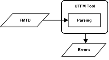
a process for aautomated analysis operationon UTFM models in Figure 2.14. The first
step in the process,parsingandvalidating, requires a FMTD and a configuration. Both are
parsed and type checked before they are translated to Z3, to be checked for satisfiability.
After validating that there is a satisfing model, there is the choice to perform constraint
propagationwith or withoutunfoldingthe configuration. The propagation process returns a
new configuration (Configuration∗). The configuration could be configured further and
iterate through the analysis process. The three steps forautomated analysisare:validating,
unfolding, andconstraint propagation.
Figure 2.14: Automated analysis process.
Parsing & Validating.After parsing and type checking the type declaration and
configura-tion are interpreted. Using the mapping rules discussed in the previous subsecconfigura-tion the model
is translated to Z3. If the configuration isinvalidwith regard to the provided type declaration
the analysis process is terminated. Otherwise the process continues withconstraint
propaga-tionor theunfolding algorithm. As the latter is followed byconstraint propagationas well,
we elaborate on this operation first.
Constraint Propagation.A fundamental concept in classical feature modeling tools is for
users to never specify an configuration that fails to satisfy all feature model constraints
[18]. Only valid partial configurations can be specified. This capability is accomplished by
constraint propagation: all facts that are inferrable from a given set of facts are determined
propagation is performed using Janota’s algorithm [21]. The referenced algorithm reasons
on features with a selection value, in UTFM the analysis is performed on instances, this does
not affect the algorithm. The Janota’s algorithm is summarized in the following points:
• if there is a valid configuration for which an undecided instance can betrue and
another valid configuration for which that instance can befalse: the instance remains
undecided. That is, a user has the freedom to decide whether or not to select the
instance at a future time.
• if the only remaining valid configurations require the instance to betrue, the instance
is assertedtrue.
• if the only remaining valid configurations require the instance to befalse, the instance
is assertedfalse.
• there are no valid configurations (no matter the selection value of the instance), then
there is a contradiction in the feature model or with the current configuration as no
products are possible.
The UTFM interpretation of the algorithm asserts for eachundecidedinstance in the
con-figuration consecutivelytrueandfalseand validates the models in the Z3 prover. Based on
returned satisfiability of the models the instance becomes configured or remains
unconfig-ured.
In Figure 2.15 we provide a configuration of theGraphLibraryFMTD (Figure 2.2).
In the configuration there are severalundecidedinstances which the algorithm will try to
configure throughconstraint propagation. Figure 2.16 shows the result from the algorithm,
three instances are propagated, two remainundecided. The first cross-tree constraint implies
that the instancesUndirected1andWeighted1must be propagated totrue. Due to this
propagation,Directed1is propagated tofalse. Because the group cardinality ofEdgeType1
process to considers all possible propagations, all possible instances have to be declared in a
configuration. To obtain such a configuration we introduce theunfoldingprocess, to generate
maximum instances for all feature types. The algorithm generates instances up to the upper
bound of a feature types’ instance cardinality. We assume that this is the maximum, even
though in theory there are implicitly, infinitely manyundecidedinstances. The process is
calledunfoldingas the instance tree will be unfolded in every node.
Algorithm 2.1Unfolding Algorithm
1: procedureUNFOLDING(Instancei)
2: FeatureTypeft←getFeatureType(i)
3: FeatureType[ ]group←getChildTypes(ft)
4: foreachchildTypeingroupdo
5: (Intlower, Intupper)←getInstanceCardinality(childType)
6: Instance[ ]instances←getChildInstances(i,childType)
7: forcount(instances)<upperdo
8: Instancenew←generateInstance(childType, “undecided”)
9: instances←instances ∪[new]
10: setChildInstances(i,childType, instances)
11: foreachinstanceininstancesdo
12: ifselection(instance)=“true”orselection(instance)=“undecided”then
13: UNFOLDING(instance of feature tree)
14: main
15: Instancei←rootinstance
16: UNFOLDING(i)
The process is based on three steps, and starts in the root instance of a configuration:
(1) Forall child feature types in the group relation of the instance, the algorithm checks if
there are as many instances configured as the upper bound of the instance cardinality
as the feature types permits;
(2) If this is not the case, instances of the child feature type are generated with the selection
(3) The process recursively proceeds to step 1 for alltrueorundecidedinstances7
The described unfolding process is provided in pseudo code in Algorithm 2.1. The algorithm
uses the following functions:
getFeatureType(Instance) Returns the feature type of the provided instance;
getChildTypes(FeatureType) Returns the set of feature types that are children of the given
feature type;
getInstanceCardinality(FeatureType) Returns the instance cardinality of a feature type;
getChildInstances(Instance,FeatureType) Returns the instances of a particular feature
type from the group relation of the provided instance, this is a set of instances;
setChildInstances(Instance,FeatureType,Instances) Assigns the set of instances for
FeatureTypeof the parentInstancetoInstances;
generateInstance(FeatureType,Selection) Returns a generated instance of a feature
type, the instance has a generated name, and the given selection value;
selection(Instance) Returns the selection value of an instance.
The constraint language uses exists, which suggests that we need to introduce
quantifications to the problem model. By unfolding and mappingexists(A)predicates to Z3 disjunctive assertionsA1∨A2∨. . .∨Au, we avoid first-order logic in Z3 decision problems
and use equivalent propositional formulae. Using theunfoldingalgorithm during automated
analysis of configuration, all possible products are considered against the set of specified
constraints in the type declaration. Our proposed semantics on instances have been reduced
to a well-known (and simpler) problem that makes use of propositional logic [4].
The configuration provided in Figure 2.16 is unfolded in Figure 2.17. Notice how the
generated instance have a randomized name. By configuring allundecidedinstances tofalse
7Falseinstances do not have to be unfolded. Possible child instances are all propagated to false and will
the configuration is completely configured. We can regard this as the end of a configuration
process. By using this configuration as input for the unfolding and propagating operations
an isomorphic configuration is returned (Figure 2.18), no instances are generated, none are
propagated. By omitting everything but the selected instances in the configuration we obtain
the product specification (fullconfiguration) illustrated in Figure 2.19 (notice the similarity
with Figure 2.7, however this configuration represents a set of products).
1 G r a p h L i b r a r y : G r a p h L i b r a r y 1
2 group :
3 E d g e T y p e : E d g e T y p e 1
4 group : {
5 U n d i r e c t e d : U n d i r e c t e d 1
6 ( false ) D i r e c t e d : D i r e c t e d 1
7 }
8 ( u n d e c i d e d ) Se arch : S e a r c h 5 4 3 5 6
9 group : {
10 ( u n d e c i d e d ) BFS : B F S 8 9 3 3 4
11 ( u n d e c i d e d ) DFS : D F S 2 6 7 3 0
12 }
13 W e i g h t e d : W e i g h t e d 1
14 A l g o r i t h m : A l g o r i t h m 1
15 group :
16 ( false ) Cycle : Cy cle1
17 ( u n d e c i d e d ) S h o r t e s t P a t h : S h o r t e s t P a t h 9 2 1 2 4
18 MST : MST1
19 group : {
20 ( u n d e c i d e d ) Prim : Prim1
21 ( u n d e c i d e d ) K r u s k a l : K r u s k a l 1
22 }
23 ( u n d e c i d e d ) T r a n s p o s e : T r a n s p o s e 4 2 1 6 6
Chapter 3
Feature Replication
We allow feature replication to UTFM and describe how it affects our type declarations and
the analysis of its configurations:
1. We explain how previous researchers have defined feature replication;
2. We give our interpretation of replication and how is it manifested in UTFM;
3. We show the effect of replication on the analysis of models and their translation to Z3.
Feature replication has a significant influence on the design of UTFM, which explains design
decisions made in the previous chapter as much as it forces restrictions on the language, that
will surface when we extend UTFM with feature attributes in Chapter 4.
3.1
Replication of Features
Czarnecki et al. in 2005 [14] first introduced the notion of having multiple clones of a feature.
Feature cardinality allowed thecloningof classical features, in UTFM vocabulary this is
translated to: feature replicationwhich allows there to bemultiple instancesof a feature
type in a configuration. Czarnecki’s proposal distinguishes differences between features,
3.2
Multiple Instances in UTFM
The structure of UTFM, explained in the previous chapter does not have to be changed to
support multiple instances of features; just lifting the restriction of allowing only singleton
features is needed. The foundation of UTFM to support replication was laid out in the
previous chapter: (1)instance cardinality; (2) the introduction ofoperationson feature types
in the constraint language; (3) and alocal scopefor feature types and constraints rather than
global cross-tree constraints.
3.2.1 Type Declaration
As described in Chapter 2, cardinalities are evaluated against the number of selected instances
in a configuration in the scope of a parent instance. This is however an explicit choice as
nested feature replication can be interpreted in different ways. The paper by Michel et al.
published in 2011 [26], describes different interpretations of the semantics of group and
instance cardinalities with regard to feature replication. They provide a two by two matrix
with on the axis:
Level. The level is set to eitherglobalorlocal. The cardinality of a feature model is counted
globallyfor the entire model, or it is countedlocallyfor each instance.
Scope. The scope is set to eithertypesorinstances. Does the group cardinality is applied
oninstancesortypes.
Figure 3.2 shows on the right different interpretations of the type declaration provided
on the left, based onlevelandscope. The classification is provided in [26] and is translated
to UTFM for consistency. The interpretations are valid configurations that are possible
under the assumed semantics. In the publication by Michel et al. they choose to interpret
cardinality with thelevelset tolocaland thescopeset totypes(bottom right in Figure 3.2).
Figure 3.2: Classification of different cardinality interpretations.
(top right). The motivation for their choice was based on being able to specify optionality
for feature types. They argue that this is closer to the classical interpretation of optional
feature. Our motivation to set thescopetoinstancesis that the language is more expressible.
The optionality of feature types is easily translated with the introduction of extra optional
singleton feature types. While the other way around, restricting the total amount of child
instances with ascopeset totypescan’t be expressed easily (the same feature types need
to be declared multiple times, or complex constraints need to be introduced to the type
declaration).
In the publications by Czarnecki et al. [14, 15] on cardinalities the interpretation of
nested replication is not thoroughly explained, this is also omitted in the CVL proposal [25].
Therefore it is impossible for us to demonstrate that we preserved prior semantics for feature
replication in UTFM. Or make assumptions on their interpretation oflevelandscope.
3.2.2 Constraint Language
Given that multiple instances of a feature type is allowed, the logical operationforallcan
now be introduced to the UTFM constraint language:
ex-pression is evaluatedtruefor everyselectedinstance of a feature type that is referenced,
otherwisefalse.FeatureTypecan be any child feature type of the referenced parent
type with either a nested operation or an expression. In the case there are no selected
instancesforallreturnstrue, as no constraint is violated.1
Anexistsoperation is the logical equivalent of a disjunction between configured instances.2
Anforalloperation is equivalent to a conjunction of implications for configured instances.
These implications are interpreted as: if the instance is selected in a configuration then the
expression given in theforallshould hold. Aforalloperation constrains alltrueselected
instances of a feature type.
Let P,C,G be feature types, where P is a parent, C its child, and G a child of C
(equivalentlyGis a grandchild ofP). Consider the expressionforall(C). It means: for a givenPinstance, all selectedCinstances should betrue(“CiimpliesCi”). Such constraints
are trivial as they are always true. Forall with nested operations or expressions such
asforall(C.exists(G)), are interpreted as: for a givenP instance, all of its selected C
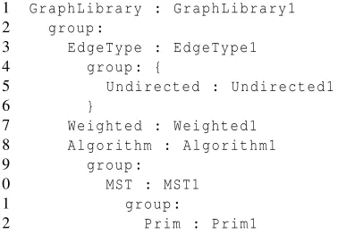
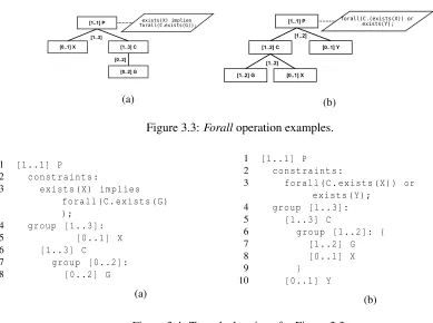
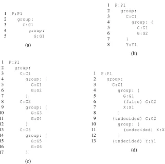
instances must have a selectedGinstance (“CiimpliesCi.exists(G)”). Figure 3.3 (graphical)
and Figure 3.4 (textual) illustrate more complex constraints usingforalloperations. The
constraints stated in the examples are described in natural language as follows:
(a) For a given instance ofP, if an instance ofXis selected then for everyselectedchildC
a grandchildGis required to beselected.
(b) For a given instance of P, either all selected C child instances have a X instance
configured totrueor there is anYinstanceselected.
The type declaration of Figure 3.3a is provided in Figure 3.4a, and for Figure 3.3b in
Figure 3.4b.
1These semantics can be compared to how universal quantifiers in first-order logic in the beginning are
always valued astrueand therefore are evaluated astruewhen quantified over an empty domain [29].
3.3
Automated Analysis with Z3
The process of automated analysis of configurations remains as stated in the previous chapter,
Section 2.4.1. We translate theforalloperation and clarify constraint propagation through an
example.
3.3.1 Translating to Z3
We show in Chapter 2 howexistsoperations are defined and translated to Z3 for singular
instances. The translation of anexists(C)operation with fourCinstances is provided in Figure 3.6; an propositionalorformula with selection variables as primitive terms. Theforall
operation translates in a similar fashion to a conjunction of implications. The implication
consists of the instances of the feature type to ensure that they are selected, and if so, the
consequent (the second proposition) must be true. This proposition is either a nested boolean
operation or an expression (just a feature type reference results in a trivial implication;Xi
implies Xi).
1 ( ass ert
2 ( or P1 . C1
3 ( or P1 . C2
4 ( or P1 . C3 P1 . C4 )
5 ) ) )
Figure 3.6: Z3 translation of anexistsoperation on a non singular feature type.
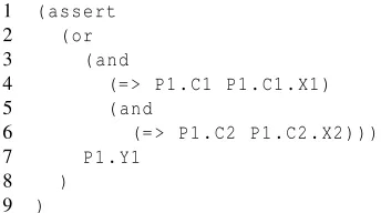
The translation of the constraint of Figure 3.3b,forall(C.exists(X))or exists(Y); , that uses aforalloperation, is provided in Figure 3.7. The translation is based on the
con-figuration specified in Figure 3.5d, in which twoC instances are declared, with each an
Xinstance. Translated to Z3 the assert on the Z3 model representing theforalloperation,
consists of a conjunction of two implications. These conjunctions are, along with theY
instance, propositions in anorexpression. For the stated assert statement to betruethe Z3
theorem prover will assign eitherC2andX2totrue,Y1totrueor all three instances tofalse
1 ( ass ert
2 ( or
3 ( and
4 (= > P1 . C1 P1 . C1 . X1 )
5 ( and
6 (= > P1 . C2 P1 . C2 . X2 ) ) )
7 P1 . Y1
8 )
9 )
Figure 3.7: Z3 translation of cross-tree constraint of Figure 3.3b using Figure 3.5d .
3.3.2 Constraint Propagation
We continue using the type declaration of Figure 3.3b as a running example, for now to
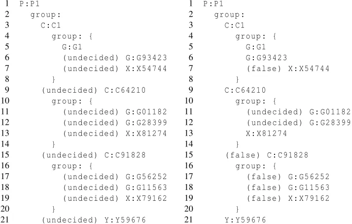
illustrate the unfolding and propagating process. The unfolded configuration of Figure 3.5a,
is provided in Figure 3.8a. Notice that the generatedundecidedinstance have a randomized
instance name. Also note that the unfolding algorithm only generates instances up to the
maximum of the instance cardinality while in theory it could generate infinitelyundecided
instances, in the process of making the undecided explicit.
In this unfolded configuration we select the instancesG93423,C64210andX81274
and run the propagating process, the result is provided in Figure 3.8b. Due to the constraint
that is declared in the type declaration theYinstance is propagated totrue(Line 21). Other
instances are propagated tofalse(Line 7, Lines 15–19), the group cardinalities do not permit
more instances to be selected. The instancesG01182andG28399remainundecidedas the
Chapter 4
Attributed Feature Models
We extend the UTFM language with attributes in this chapter. We describe:
1. The classical semantics for attributed feature models;
2. How attributes extend the UTFM language;
3. A translation of classical attributed feature models to UTFM;
4. And how attribute semantics of UTFM translate to Z3 and work in automated analysis
of attributed feature models.
In these section we elaborate on feature attributes in UTFM, an important building block for
the constraint language of UTFM.
4.1
Classical Attributed Feature Models
As with classical feature models in Chapter 2, we require UTFM to be backwards compatible
withAttributed Feature Modelspublished previously. Classical feature models did not allow
features to have attributes, even though their presence and usage had been discussed by
4.2
Attributes in UTFM
Introducing attributes into the UTFM language requires an extension of the syntax and
semantics previously defined. Attributes are declared in the FMTD and are assigned values
during configuration. For each instance, of a feature type, the attribute set (declared and
constrained in the type declaration) has values. This is consistent with prior work on
attributes in classical feature models where features just had singular instances.
4.2.1 Type Declaration Extensions for Attributes
Attribute declarationsare specified in the type declaration and consist of anameand atype
(domain of the attribute). Four attribute types are distinguished in UTFM:integer, real,
booleanandstring. All attributes (regardless of their type) must have unique names with
respect to their feature type. When an instance is created all attributes have their value set to
undecided, unless a specific value is provided in the configuration. Anundecidedvalue can
be determined by constraint propagation or configured at a later stage.1 Each attribute can
be referenced in arithmetic constraints of the FMTD.
Integer Attributes. Integer attributesare declared as typeInt. In configurations of a type
declaration integer values are assigned to these attributes.
Real Attributes. Real attributes(declared asReal) are used in the same fashion asinteger
attributes. In arithmetic expressions bothintegerandrealattributes can be mixed; type
casting anintegerto arealin a configuration does not change the value, the other way
around will result in dropping the decimal value of thereal, the value is not rounded
to the nearestinteger.
Boolean Attributes. Boolean attributes (declared asBool) have not thoroughly made their
way into attributed feature models. Yet boolean attributes play an important role in
1Z3 allows undecided attributes (integer, real and boolean) as the prover will look for possible values for the
substitution possibilities in the FMTD constraint language, which is explained in the
Substitution item of Section 4.2.2. Furthermore boolean attributes can be used to
reduce2feature models in a process explained by Classen et al. [11], in which features
types are replaced by boolean attributes.
String Attributes. String attributes (declared asString) provide possibilities to specify
options, names, descriptions, etc. for instances, providing extra information for the
implementation of a product. These attributes can’t be referenced in constraints.
A portion of Figure 4.1 (namely theInternetConnectionsubtree) is shown in Figure 4.2,
where attribute declarations are specified in the same parallelogram as cross-tree constraints,
separated by a horizontal line; attributes above the line, constraints thereunder. The UTFM
syntax to declare attributes is an “attributes:” statement followed by attribute declarations.
The translation of Figure 4.2 to UTFM is given in Figure 4.3. In the FMTD astringand
booleanattribute have been added toInternetConnectionto illustrate the possibilities.
In anticipation of the next subsection that elaborates on cross-tree constraints and
UTFM constraint language, we briefly note the following on the constraints in the Figure 4.2.
It is impossible to directly reference the values of attributes of instances in a type declaration,
therefore a sumoperation is called on a feature type. Sumreturns the sum of all price
attributes of theselectedinstances of the referenced feature type (either:Powerline,ADSL
orWireless).
4.2.2 Constraint Language Extensions for Attributes
The FMTD constraint language is extended with new operations: assign, equality and
inequality expressions.
Assign Expression. The value of an attribute can be based on an expression. As in other
languages, the syntax for assigning a value is:name=expression;, wherenameis
2Reducinga feature model is reducing the total number of feature types in a model and the (maximum or
Figure 4.2: Part of the graphical FTMD representation of Service feature model (Figure 4.1).
1 [1.. 1] I n t e r n e t C o n n e c t i o n
2 a t t r i b u t e s :
3 Int price ;
4 Bool opt ion ;
5 Stri ng c o n n e c t i o n N a m e ;
6 c o n s t r a i n t s :
7 price = 20 + ( sum ( P o w e r l i n e . price ) + ( sum ( ADSL . price ) + sum ( W i r e l e s s . price ) ) ) ;
8 group [ 1 . . 1 ] :
9 [0.. 1] P o w e r L i n e
10 a t t r i b u t e s :
11 Int price ;
12 c o n s t r a i n t s :
13 price >= 100;
14 price <= 200;
15 [0.. 1] ADSL
16 a t t r i b u t e s :
17 Int price ;
18 c o n s t r a i n t s :
19 price >= 100;
20 price <= 200;
21 [0.. 1] W i r e l e s s
22 a t t r i b u t e s :
23 Int price ;
24 c o n s t r a i n t s :
25 price >= 150;
26 price <= 250;
Figure 4.3: Part of the FMTD of Service feature model (Figure 4.1).
the name of an attribute of the feature type andexpressionis an expression that returns
a constraint that is required to betruefor a valid configuration. Key to an assign
expression, in contrast to an equality expression, is that it deduces a value for an
attribute. Assign expressions are not allowed inside other expressions. Figure 4.3
Line 7 illustrates a assign expression, other more basic assignments are:
price=205;
connectionName="TestConnection";
options=false;
Equality Expression. The syntax of an equality expression isexpression==expression. The difference is that on the left side of the equality sign there is an expression that
is evaluated against the right side. Both left and right expressions are required to be
of the same type and the equality expression itself returns abooleanvalue.
Equal-ity expressions are allowed as constraints on their own or as propositions in other
expressions. An example of an equality expression is:
(sum(Video.price) +sum(Internet.price)) ==300;
Inequality Expression. Inequality expressions compare two expressions and return aboolean
value. Possible arithmetic inequality operations are:less than(<),Less than or equal
(<=),greater than(>), orgreater than or equal(>=), and for both arithmetic and boolean expressionsnot equal to(!=). These expressions are used in the same way as equality expressions. Examples of inequality are Figure 4.3 Lines 13–14, Lines 19–20,
Lines 25–26.
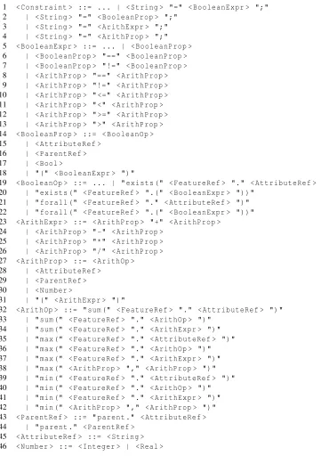
For arithmetic attributes and constraints, we introducearithmetic operations. UTFM
existsandforall. The context free grammar provided in Figure 2.3 has been extended with
the attribute constraints in Figure 4.4, the complete grammar for the cosntraint