VOLUME 3, ISSUE 4, Apr.-2017
110 | P a g e
ROBUST CONTROL OF DC MOTOR USING SLIDING MODE CONTROL
APPROACH
JAGADALE SHRIKANT
PG department College of Engineering, Ambajogai, [email protected]
S. S. SANKESWARI
PG department College of Engineering, Ambajogai, [email protected]
ABSTRACT:
Most of the industrial applications are based on the AC motor drive because of the problems associated with the control of the DC motor drives. Authors have tried to address the problems associated with the DC drives. Sliding mode control of the DC machine is the scope of the study of this paper. Authors have focused the scope of the study to the DC drives used in industries. Reducing the disturbances is one of the advantages of the experiment carried out. The method implemented was found suitable to reducing dynamic chattering of the drive. The simulation model is developed and it was found suitable to improve the performance of the system.
KEYWORDS: DC drives, control of drives, sliding mode control, etc.
I. INTRODUCTION:
The technology implemented was firstly introduced in 1950. Variable structure control is useful for MIMO and nonlinear systems [1], [2]. The VSC systems are also found suitable for several robust control systems. The cluster of research has been carried out for betterment of the performance of the drives and various systems have been developed and implemented by the researchers in past few years. All the design procedures will be carried out in the physical coordinates to make explanations as clear as possible. The system response is judged by the performance index. The system is found useful for the high frequency switching.
II. DYNAMIC MODELING OF DC MACHINE: Fig.1 shows the model of DC motor with constant excitation is given by
Following state equations [1],[3],[7].
l
τ
i
k t
dt
d
j
λ
Ri
u
dt
di
L
(1)Where
i Armature current ω Shaft speed
R Armature resistance λ0 Back emf constant
τl Load torque
u Terminal voltage
j Inertia of the motor rotor and load L Armature inductance
kt Torque constant
Its motion is governed by second order equations (1) with respect to armature current, i and shaft speed w with voltage u and load torque τ1. A low power-rating device
can use continuous control. High power rating system needs discontinuous control. Continuously controlled voltage is difficult to generate while providing large current.
III. SLIDING MODE CONTROL DESIGN:
DC motors have been dominating the field of adjustable speed drives for a long time because of excellent operational properties and control characteristics. In this section different sliding mode control strategies are formulated for different objectives e.g. speed control, torque control and position control.
A. CURRENT CONTROL:
Let i* be reference current providing by outer control loop
and i be measured current. Consider a current control problem, by defining switching function
s
i
*
i
(2)Design a discontinuous control as
u
u
sign
(s)
(3)VOLUME 3, ISSUE 4, Apr.-2017
s
u
L
1
)
L
λ
i
L
R
dt
di
(
s
s
s
(4)Choice of control u0 as
λ
i
R
dt
di
L
u
Makes (4)0
s
s
Which means that sliding can happen in s = 0 [4]. B. Speed controlLet ω* be the reference shaft speed, then the second
order motion equation with respect to the error (e = ω*- ω) is of form.
tate variable x1=e &
x
2
e
u
b
f(t)
2
x
2
a
1
x
1
a
2
x
2
x
1
x
(5) WhereJL
t
k
b
&
L
R
2
a
,
JL
λ
t
k
1
a
are constant values.
J
/
l
τ
a
JL
/
1
τ
R
1
a
2
a
f(t)
The slidingsurface and discontinuous control are designed as
(s)
sgn
u
u
)
(
dt
d
)
(
c
s
(6)This design makes the speed tracking error e converges to zero exponentially after sliding mode occurs in s = 0, where c is a positive constant determining the
convergence rate .for implementation of control (6),angle of acceleration (
x
2
e
) is needed.The system motion is independent of parameters a1, a2, b
and disturbances in g(t). Combining (1) & (6) produces
)
t
k
i
R
(
JL
t
k
l
τ
J
1
)
l
τ
i
t
k
(
J
c
*
c
g(t)
where
u
JL
t
k
g(t)
u
JL
t
k
)
w
t
k
i
R
(
JL
t
k
τ
J
1
)
l
τ
i
λ
(
J
c
c
s
l
(8) If0
s
s
,
g(t)
t
k
L
J
u
(9)Then sliding mode will happen [6].
The mechanical motion of a dc motor is normally much slower then electromagnetic dynamics.
It means that L<<J in (1).
Following reduced order control methods proposed below will solve chattering problem without measuring of current and acceleration (x2).
Speed tracking error is ωe=ω*-ω. The dc motor model
(1) in terms of ωe:
*
j
l
τ
i
kt
dt
e
d
j
)
e
(
λ
Ri
u
dt
di
L
(10)Let L be equal to zero due to L << j. Then (10) becomes with L=0
*
j
1
τ
u
R
t
k
)
e
(
R
λ
i
(11) Substituting (11) into (10) results in.
j
*
1
τ
u
R
t
k
)
e
(
R
λ
t
k
dt
e
d
j
12)Equation (12) is a reduced order (first order) model of DC motor.
The discontinuous control is designed as
u
u
sgn
(
e
)
(13)and the existence condition for the sliding mode ωe=0 will
be
t
k
*
R
j
t
k
R
1
τ
)
e
(
λ
u
(14)The principle advantage of the reduced order based method is that the angle acceleration
(
x
2
e
)
is not needed for designing sliding mode control [1].The unmodeled dynamics (1) may excite non-admissible chattering. Fig.3 shows the control structure based on reduced order model and observer state.
Let us design an a asymptotic observer to estimate ωe [6 ]
: ) e ( 1 l * j 1 τ u R t k ) e ( R λ t k dt e d
j
VOLUME 3, ISSUE 4, Apr.-2017
112 | P a g e
* j 1 τ u R t k ) e ( R λ t k dt e d
j
)
e
(
2
l
dt
l
τ
d
(15) Where ew
Estimated error e ee
Speed trackingerror l1,l2 observer gainThe discontinuous control designed using estimate
state
w
e
[ ] will be
u
u
sgn
(
e
)
(16) the sliding mode will happen if) e ( t k R 1 l t k * R j t k R 1 τ ) e ( λ
u
(17)
And
0
&
τ
0
.Chattering can be eliminated by using reduce observer states. The sliding mod occurs in the observer loop, which does not contain unmodelled dynamics.
C Position control
To consider the position control issue, it is necessary to augment the motor equations (1) with
dt
dθ
(18)
Where θ denotes the rotor position.
The switching function s for the position control is selected as
θ)
θ
(
2
c
)
θ
*
θ
(
1
c
)
θ
*
θ
(
s
(19) and the discontinuous control is
u
u
sgn
(s)
(20) Combining (1) (18 ) (19)u
JL
t
k
h(t)
s
(21) Where)
t
k
(Ri
JL
t
k
l
τ
J
1
2
c
)
l
τ
i
t
(k
J
1
c
2
c
*
1
c
*
h(t)
(22)Choice of u0 as
h(t)
t
k
L
J
0
u
(23)Makes
s
s
0
which means that sliding mode can happen s=0 with properly chosen c1 & c2 .We can make velocity
tracking error e = w* - w converges to zero. D. Torque Control
The torque control problem by defining switching function
s
τ
τ
(24)As the error between the reference torque τ* and the real
torque τ developed by the motor. Design a discontinuous control as
u
u
sign
(s)
(25)Where u0 is high enough to enforce the sliding mode in s=0,
which implies that the real torque τ tracks the reference
torque τ*.
u
L
t
k
f(t)
u
L
t
k
L
t
k
λ
L
Ri
t
k
τ
i
t
k
*
τ
s
(26) WhereL
t
k
λ
L
Ri
t
k
*
τ
f(t)
Depending on the referencesignal .for
f(t)
t
k
L
u
u
s
0
L
t
k
sf(t)
s
s
(27)So sliding mode can be enforced in s = 0.
IV. SIMULATION RESULTS:
To show the performance of the system the simulation result for the speed control of DC machine is depicted. Rated parameters of the dc motor used to verify the design principle are
5 hp, 240V, R=0.5 Ω, L=1mH, j =0.001 kgm2, kt=
0.008MmA-1
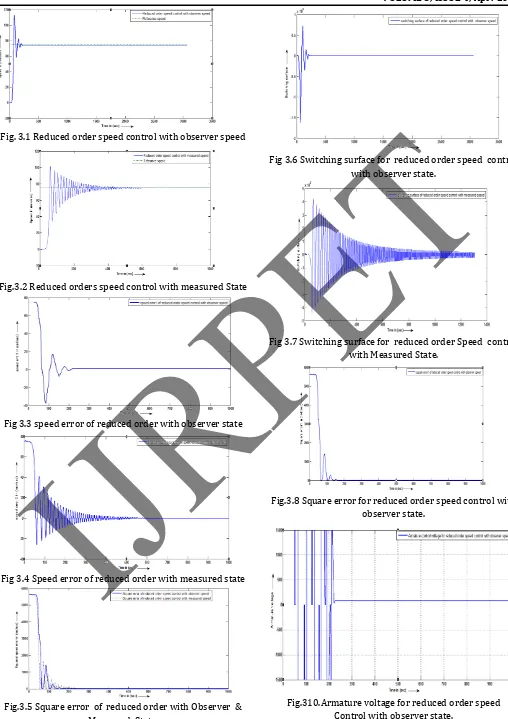
λ0= 0.001vs rad-1 and τl=Bω where b=0.01 Nms rad-1 fig.3.1,3.2,3.3,&3.4 depicts the simulation result of the
VOLUME 3, ISSUE 4, Apr.-2017
Fig. 3.1 Reduced order speed control with observer speed
Fig.3.2 Reduced orders speed control with measured State
Fig 3.3 speed error of reduced order with observer state
Fig 3.4 Speed error of reduced order with measured state
Fig.3.5 Square error of reduced order with Observer & Measured State.
Fig 3.6 Switching surface for reduced order speed control with observer state.
Fig 3.7 Switching surface for reduced order Speed control with Measured State.
Fig.3.8 Square error for reduced order speed control with observer state.
VOLUME 3, ISSUE 4, Apr.-2017
114 | P a g e
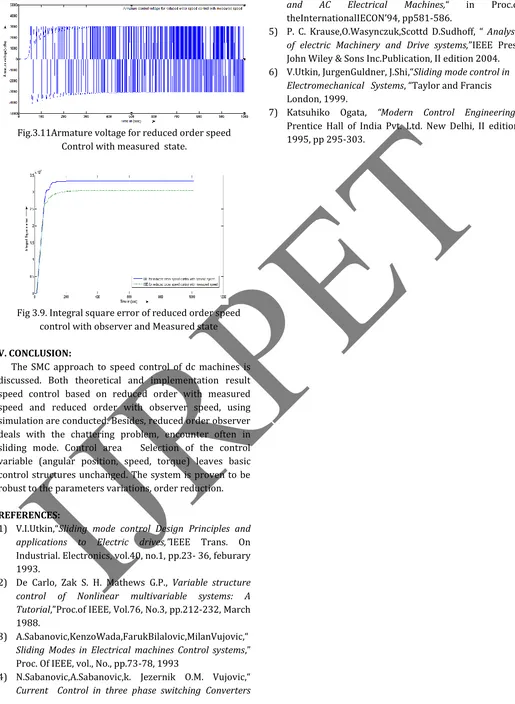
Fig.3.11Armature voltage for reduced order speed Control with measured state.
Fig 3.9. Integral square error of reduced order speed control with observer and Measured state
V. CONCLUSION:
The SMC approach to speed control of dc machines is discussed. Both theoretical and implementation result speed control based on reduced order with measured speed and reduced order with observer speed, using simulation are conducted. Besides, reduced order observer deals with the chattering problem, encounter often in sliding mode. Control area Selection of the control variable (angular position, speed, torque) leaves basic control structures unchanged. The system is proven to be robust to the parameters variations, order reduction.
REFERENCES:
1) V.I.Utkin,“Sliding mode control Design Principles and applications to Electric drives,”IEEE Trans. On Industrial. Electronics, vol.40, no.1, pp.23- 36, feburary 1993.
2) De Carlo, Zak S. H. Mathews G.P., Variable structure control of Nonlinear multivariable systems: A Tutorial,”Proc.of IEEE, Vol.76, No.3, pp.212-232, March 1988.
3) A.Sabanovic,KenzoWada,FarukBilalovic,MilanVujovic,“ Sliding Modes in Electrical machines Control systems,” Proc. Of IEEE, vol., No., pp.73-78, 1993
4) N.Sabanovic,A.Sabanovic,k. Jezernik O.M. Vujovic,“ Current Control in three phase switching Converters
and AC Electrical Machines,“ in Proc.of
theInternationalIECON’94, pp581-586.
5) P. C. Krause,O.Wasynczuk,Scottd D.Sudhoff, “ Analysis of electric Machinery and Drive systems,”IEEE Press John Wiley & Sons Inc.Publication, II edition 2004. 6) V.Utkin, JurgenGuldner, J.Shi,“Sliding mode control in
Electromechanical Systems, “Taylor and Francis London, 1999.