Efficient Key-policy Attribute-based Encryption for General
Boolean Circuits from Multilinear Maps
Constantin C˘at˘alin Dr˘agan and Ferucio Laurent¸iu T¸ iplea
Department of Computer Science “Al.I.Cuza” University of Ia¸si
Ia¸si 700506, Romania
e-mail:{constantin.dragan,fltiplea}@info.uaic.ro
Abstract. We propose an efficient Key-policy Attribute-based Encryption (KP-ABE) scheme for general (monotone) Boolean circuits based on secret sharing and on a very particular and simple form of leveled multilinear maps, called chained multilinear maps. The number of decryption key components is substantially reduced in comparison with the scheme in [6], and the size of the multilinear map (in terms of bilinear map components) is less than the Boolean circuit depth, while it is quadratic in the Boolean circuit depth for the scheme in [6]. Moreover, it is much easier to find chained multilinear maps than leveled multilinear maps. Selective security of the proposed schemes in the standard model is proved, under the decisional multilinear Diffie-Hellman assumption.
1 Introduction
Attribute-based encryption(ABE) was introduced in [10] as a generalization ofidentity-based encryption [11]. There are two forms of ABE: key-policy ABE (KP-ABE) and ciphertext-policy ABE (CP-ABE) [8, 2]. A KP-ABE scheme encrypts messages taking into considera-tion specific sets of attributes; decrypconsidera-tion keys are distributed for an entire access structure build over the set of attributes so that correct decryption is allowed only to authorized sets of attributes (defined by the access structure). A CP-ABE scheme proceeds somehow vice-versa than a KP-ABE scheme: messages are encrypted together with access structures while decryption keys are given for specific sets of attributes. A general approach to specify access structures is the one based on Boolean circuits with exactly one output wire [12]. Roughly speaking, each attribute is associated with an input wire of the Boolean circuit. A set of attributes evaluates the circuit to one of the truth values. If this is the truth value true, then the set of attributes is considered authorized. The set of all authorized sets of attributes defines an access structure.
scheme for functions that can be represented as (polynomial-size) arithmetic circuits. The scheme is based on the LWE problem and it can naturally handle access structures definable as general Boolean circuits. Its decryption key size is quadratic in the circuit depth, while for the schemes proposed in [6, 7] it is linear in the number of Boolean gates or wires in the circuit. On the other side, the size of its public parameters is quadratic in the number of input wires, while for the schemes in [6, 7] it is linear (in the number of input wires). Contribution The KP-ABE schemes for general Boolean circuits proposed so far are either based on leveled multilinear maps [6] or on the LWE problem [7, 3]. In this paper we propose a new KP-ABE scheme based on a very particular and simple form of leveled multilinear maps, called chained multilinear maps. Our scheme is more efficient than the scheme in [6] both in terms of the decryption key size and of the multilinear map size and construction. The size of the chained multilinear maps we use is less than the circuit depth, while the leveled multilinear maps used in [6] have a quadratic size in the circuit depth. Moreover, it is much easier to define chained multilinear maps than leveled multilinear maps: once definedk bilinear maps fromGi×G1 intoGi+1, 1≤i≤k, any generator of the groupG1, together with the bilinear maps, defines a chained multilinear map.
Our construction uses general Boolean circuits where the logic gates of fan-out two or more are split into logics gates of fan-out one and FANOUT-gates whose role is to multiply the output of logic gates. Then, a secret sharing procedure works top-down to share some secret, and a bottom-up procedure reconstructs a “hidden” form of the secret by using chained multilinear maps. The generator of the chained multilinear map is changed each time a FANOUT-level (level that contains FANOUT-gates) is reached. Decryption key components are assigned to input wires, FANOUT-gates, and to circuit FANOUT-levels. The size of the decryption key is thus a third of the size of the decryption key in the construction in [6].
The selective security of our KP-ABE schemes is proved in the standard model under the decisional multilinear Diffie-Hellman assumption.
Paper organization The paper is organized into eight sections. The next section fixes the basic terminology and notation used throughout the paper. The third section discusses the scheme in [6] and how it thwarts the backtracking attack, and gives an informal overview of our solution. Our construction is presented in the fourth section, its security is discussed in the fifth one, while the sixth section presents some comparisons between our scheme and the one in [6]. Section seven proposes some extensions of our scheme, and the last one concludes the paper.
2 Preliminaries
This section fixes the terminology and notation used in our paper.
Access structures Recall first that [12], given a non-empty finite setU whose elements are calledattributes in our paper, anaccess structure overU is any setS of non-empty subsets of U.S is called monotoneif it satisfies the following monotonicity property:
(∀B⊆ U)((∃A∈ S)(A⊆B) ⇒ B ∈ S)
It is customary to represent access structures by Boolean circuits (for more details about Boolean circuits the reader is refereed to [1]). A Boolean circuit has a number of input wires (which are not gate output wires), a number of output wires (which are not gate input wires), and a number of OR-, AND-, and NOT-gates. The OR- and AND-gates have two input wires, while NOT-gate has one input wire. All of them may have more than one output wire. That is, the fan-in of the circuit is at most two, while the fan-out may be arbitrarily large but at least one. A Boolean circuit ismonotoneif it does not have NOT-gates, and it is of fan-out one if all gates have fan-out one. In this paper all Boolean circuits have exactly one output wire (for the sake of simplicity they will also be called “Boolean circuits”). Boolean circuits of fan-out one (with one output wire) correspond to Boolean formulas.
If the input wires of a Boolean circuit C are in a one-to-one correspondence with the elements of U, we will say that C is a Boolean circuit over U. Each A ⊆ U evaluates the circuit C to one of the Boolean values 0 or 1 by simply assigning 1 to all input wires associated to elements in A, and 0 otherwise. We will writeC(A) for the value obtained by evaluating C forA. The access structure defined by a Boolean circuitC is the set of all A
that evaluatesC to 1.
Attribute-based encryption A KP-ABE scheme consists of four probabilistic polynomial-time (PPT) algorithms [8]:
Setup(λ): this is a PPT algorithm that takes as input the security parameterλand outputs a set of public parametersP P and a master key M SK;
Enc(m, A, P P): this is a PPT algorithm that takes as input a messagem, a non-empty set of attributesA⊆ U, and the public parameters, and outputs a ciphertextE;
KeyGen(C, M SK): this is a PPT algorithm that takes as input an access structureC(given as a Boolean circuit) and the master key M SK, and outputs a decryption key D (for the entire Boolean circuitC);
Dec(E, D): this is a deterministic polynomial-time algorithm that takes as input a cipher-textE and decryption key D, and outputs a messagem or the special symbol ⊥.
The following correctness property is required to be satisfied by any KP-ABE scheme: for any (P P, M SK)←Setup(λ), any Boolean circuitCover a setU of attributes, any message
m, any A ⊆ U, and any E ← Enc(m, A, P P), if C(A) = 1 then m = Dec(E, D), for any
D←KeyGen(C, M SK).
Security models We consider the standard notion of selective security for KP-ABE [8]. Specifically, in the Init phase the adversary (PPT algorithm) announces the set A of at-tributes that he wishes to be challenged upon, then in theSetupphase he receives the public parametersP P of the scheme, and inPhase 1oracle access to the decryption key generation oracle is granted for the adversary. In this phase, the adversary issues queries for decryp-tion keys for access structures defined by Boolean circuitsC, provided thatC(A) = 0. In the Challengephase the adversary submits two equally length messagesm0andm1 and receives the ciphertext associated toA and one of the two messages, saymb, whereb← {0,1}. The
adversary may receive again oracle access to the decryption key generation oracle (with the same constraint as above); this is Phase 2. Eventually, the adversary outputs a guess
Theadvantageof the adversary in this game is defined asP(b0=b)−1/2. The KP-ABE scheme is secure (in the selective model) if any adversary has only a negligible advantage in the selective game described above.
Leveled multilinear maps and the decisional MDH assumption [6, 5, 4] GivenG1, G2, and
GT three multiplicative cyclic groups of prime orderp, a map e:G1×G2 → GT is called
bilinearif it satisfies:
– e(xa, yb) =e(x, y)ab, for anyx∈G1,y∈G2, and a, b∈Zp;
– e(g1, g2) is a generator of GT, for any generatorsg1 of G1 and g2 of G2.
Given k multiplicative groups G1, . . . , Gk of the same prime order p with generators
g1, . . . , gk, respectively, a sete={ei,j :Gi×Gj →Gi+j|i, j≥1, i+j≤k}of bilinear maps
is caled a leveled multilinear mapifei,j(gai, gjb) =gabi+j, for all i, j≥1 with i+j≤kand all
a, b∈Zp.
The decisional Multilinear Diffie-Hellman (MDH) problem for e is the problem to distinguish between gsc1···ck
k and a random element in Gk given g1, g s
1, g
c1 1 , . . . , g
ck
1 , where
s, c1, . . . , ck are randomly chosen fromZp.
The decisional MDH assumption for e states that no PPT algorithm A can solve the decisional MDH problem for ewith more than a negligible advantage.
The (leveled) multilinear maps defined as above should be viewed at a generic level. Practical construction have also been obtained: [5] proposes a construction based on ideal lattices, while [4] proposes a construction based on integers. Both of them are developed inside the formalism calledgraded encoding systems.
3 An Informal View of Our Construction
Our approach to construct a KP-ABE scheme uses both secret sharing as in [8] and multi-linear maps as in [6]. To clearly understand how these two techniques are combined, let us briefly recall them.
The approach in [8] works only for monotone Boolean formulas. The main idea is quite elegant and simple, and can be summarized as follows:
– choose a bilinear mape:G1×G1→G2 and a generatorg ofG1;
– to encrypt a message m by a setA of attributes, just multiply m by e(g, g)ys, wherey
is a random integer chosen in the setup phase and sis a random integer chosen in the encryption phase. Moreover, an attribute dependent quantity is also computed for each attribute i∈A;
– the integer y is then shared to all attributes so that it can be recovered only by the authorized sets of attributes (the authorized sets are defined by monotone Boolean formulas). The shares associated to attributes are then used to compute the decryption key (which consists of a key component for each attribute);
– in order to decryptme(g, g)ys, one has to computee(g, g)ys. This can be done only ifA
is an authorized set of attributes. The computation of e(g, g)ys is bottom-up, starting
from the key components associated to the attributes in A.
case of OR-gates, any value computed at an input wire should be the same with the value computed at the other input wire (this is because of the way secrets are shared at OR-gates). Therefore, knowing the value at one of the input wires of an OR-gate implicitly leads to the knowledge of the value at the other input wire (although these values are computed by different workflows), and this value can further “migrate” to other gates if the gate fan-out is two or more. This aspect leads to the possibility of computing the value at the output wire of the circuit starting from values associated to some unauthorized set of attributes. The backtracking attack cannot occur when access structures are defined by Boolean formulas as in [8] because, in such cases, the input wires of OR-gates are not used by any other gates. In order to thwart the backtracking attack, [6] uses a “one-way” construction in eval-uating general monotone Boolean circuits (the encryption technique is almost the same as the one in [8]). The idea is the next one:
– consider a leveled multilinear map (as the one in the previous section);
– the key components are associated to the input wires of the circuit and to each gate output wire (in [6], each gate has one output wire which may further be used by more than one gate);
– the circuit is evaluated bottom-up and the values associated to output wires of gates on levelj are powers ofgj+1;
– as the mappings ei,j work only in the “forward” direction, it is not feasible to invert
values on the level j+ 1 in order to obtain values on the level j, defeating thus the backtracking attack.
Now, our approach can be described as follows. First, the logic gates of fan-out two or more are split into logic gates of fan-out one and FANOUT-gates. A FANOUT-gate multiplies the output of a logic gate. Then, a secret sharing procedure is used top-down to share a secret to all attributes (input wires of the circuit). There are two main tricks here:
1. the shares associated to the output wires of a FANOUT-gate are processed via a random value associated to the input wire of the gate, and this random value is passed down to logic gates for sharing;
2. the share associated to the output wire of a logic gate is shared among its input wires by taking into consideration the input wire levels of the gate.
When all input wires of the circuit get their shares, a “secret reconstruction” procedure evaluates bottom-up the circuit by computing values to each wire. Each value is the power of some group generator, and the generator is changed only when a FANOUT-level (level that contains FANOUT-gates) is reached. Due to the way secrets are shared, the multilinear map we use consists of justr+1 bilinear mapsei:Gi×G1 →Gi+1with no other constraints, 1≤i≤r+ 1 (rdenotes the number of FANOUT-levels). As the bilinear maps ei work only
in the forward direction, our scheme defeats the backtracking attack.
4 Our Construction
1. each Boolean circuit has a number of circuit input gates, but at least one. Each input gate has no input wire and exactly one output wire (which is called acircuit input wire); 2. each Boolean circuit has exactly onecircuit output gate, which has one input wire (which
is called thecircuit output wire) and no output wire;
3. each Boolean circuit has a number oflogic gatesof two types: OR-gates and AND-gates. Each of them has exactly two input wires and exactly one output wire;
4. each Boolean circuit may have a number of FANOUT-gates. Each FANOUT-gate has exactly one input wire and at least two output wires. Their role is to propagate (multiply) the logic gate outputs;
5. no two FANOUT-gates are directly connected (no output wire of a FANOUT-gate is the input wire of another FANOUT-gate).
The restriction to Boolean circuits that are monotone does not constitute a loss of generality, as it has been shown in [6] (see page 7 in [6]).
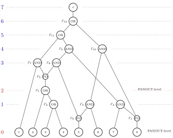
Each non-input gate of a Boolean circuit has one or two input wires and, therefore, one or twoinput gates. Figure 1 pictorially represents a Boolean circuit under our conventions (“FO” stands for “FANOUT”). Assuming that the wires are labeled, we may write the gates
Level
7
6
5
4
3
2
1
0
FO
Γ0 Γ1 FO
OR
Γ2 Γ3 AND Γ4 AND
OR
Γ5
FO
Γ6
AND
Γ7 Γ8 AND
AND
Γ9 Γ10 AND
OR
Γ11
OR
Γ12
o
1 2 3 4 5 6 7 8 FANOUT-level
FANOUT-level
Fig. 1.Boolean circuit with FANOUT-gates
as tuples (w1, w2, OR, w), (w1, w2, AN D, w), and (w, F AN OU T, w1, . . . , wj). The elements
a Boolean circuit will always be denoted by o, and the input wires by 1, . . . , n (assuming that the circuit has ninput wires).
All gates of a Boolean circuit are distributed onlevelswhich are defined as follows:
1. the 0th level, also called theinput level, consists of all circuit input gates together with all FANOUT-gates directly connected to them;
2. if the (i−1)st level has been defined and there are logic gates whose input gates are on the first (i−1) levels but at least one input gate on the (i−1)st level, then theith level consists of all such logic gates together with all FANOUT-gates directly connected to them;
3. if the (i−1)st level has been defined and there is no logic gates as above, then the ith level consists only of the output gate (this is also called theoutput levelof the circuit).
Figure 1 illustrates the way levels are counted in our Boolean circuits. For instance, the 2nd level consists ofΓ5 and Γ6.
Bylevel(Γ) we denote the level of the gateΓ. Thedepthof a Boolean circuitC, denoted
depth(C), is the number ofC’s output level. A level is called aFANOUT-levelif it contains FANOUT-gates. Remark that the input level may be a FANOUT-level, but the output level as well as its direct predecessor cannot be FANOUT-levels (in fact, assuming that no logic gate has a FANOUT-gate as input gate for both its inputs, each FANOUT-level isatisfies
i < depth(C)−2).
LetΓ be a logic gate and Γ0 be a gate such that Γ and Γ0 are directly connected and
i = Level(Γ) > Level(Γ0) = j (that is, Γ0 is an input gate of Γ). The FANOUT-level sequence from Γ toΓ0 is a sequence, possible empty, of FANOUT-level indexes defined as follows:
1. if Γ0 is an input or logic gate, then the FANOUT-level sequence from Γ to Γ0 is the sequence of all FANOUT-level numbers taken in decreasing order fromi−1 toj; 2. ifΓ0 is a FANOUT-gate, then the FANOUT-level sequence fromΓ toΓ0 is the sequence
of all FANOUT-level numbers taken in decreasing order fromi−1 to j+ 1.
As an example, in the Boolean circuit in Figure 1, (2,0) is the FANOUT-level sequence from
Γ7 to the input gate 1, and (2) is the FANOUT-level sequence from Γ8 toΓ0.
To each logic gateΓ, two FANOUT-level sequences are associated: the leftone, fromΓ
to its left input gate, and the rightone, fromΓ to its right input gate. It is clear that both of them can be empty and one of them is a prefix of the other one. These two sequences will play an important role in the sharing procedure described below.
Now, we need to fix the terminology on the multilinear maps we use in our construction.
Definition 1. A chained multilinear map is a sequence (ei|1 ≤ i ≤ k) of bilinear maps
ei :Gi×G1 → Gi+1, 1≤i≤k, where G1, . . . , Gk+1 are multiplicative groups of the same prime order p.
Remark 1. Let (ei|1 ≤ i ≤ k) be a chained multilinear map as above. If g1 ∈ G1 is a generator of G1, then gi+1 defined recursively bygi+1=ei(gi, g1) is a generator ofGi+1, for all 1≤ i≤k (because ei is a bilinear map). Therefore, (ei|1 ≤i≤ k) can be regarded as
Chained multilinear maps will be used in our construction as follows. Assume that r is the number of FANOUT-levels in the Boolean circuits we consider, and (ei|1 ≤i≤r+ 1)
is a chained multilinear map as above. A message m ∈Gr+2 will be encrypted by mgrys+2, wherey is a random integer chosen in the setup phase andsis a random integer chosen in the encryption phase. To decrypt this message, one needs to computegysr+2, and this will be done by using a secret sharing procedure and a secret reconstruction procedure.
The secret sharing procedure, denoted Share(y,C), inputs a Boolean circuit C and a valuey∈Zp, and outputs three functionsS,P, and Lwith the following meaning:
1. S assigns to each wire of C an element inZp;
2. P assigns to each output wire of a FANOUT-gate an element (also calledFANOUT-key) inG1;
3. L assigns to each FANOUT-level an element (also calledFANOUT-level-key) in G1.
The sharing procedure is the following one.
Share(y,C)
1. Initially, all gates of C are unmarked;
2. For each FANOUT-level i, 0≤i < depth(C)−2, choose uniformly at randomai ∈Zp
and assign L(i) :=gai
1 ; 3. S(o) :=y;
4. If Γ = (w1, w2, OR, w) is an unmarked OR-gate and S(w) = x, then mark Γ and assign S(w1) := xa−i11· · ·a
−1
iu modp and S(w2) := xa
−1
j1 · · ·a
−1
jv modp, where i1· · ·iu
and j1· · ·jv are the left and right FANOUT-level sequences of Γ, respectively (if the
left FANOUT-level sequence is empty, then S(w1) := x, and similarly for the other case);
5. If Γ = (w1, w2, AN D, w) is an unmarked AND-gate and S(w) = x, then mark Γ and do the followings:
(a) choosex1 uniformly at random fromZp and compute x2 such that
x= (x1ai1· · ·aiu+x2aj1· · ·ajv) modp,
where i1· · ·iu and j1· · ·jv are the left and right FANOUT-level sequences of Γ,
respectively (ifi1· · ·iu is the empty sequence then ai1· · ·aiu = 1, and similarly for
the other case);
(b) assignS(w1) :=x1 and S(w2) :=x2;
6. IfΓ = (w, F AN OU T, w1, . . . , wj) is an unmarked FANOUT-gate andS(wi) =xifor all
1≤i≤j, then markΓ and do the followings:
(a) choose uniformly at randomx ∈Zp and computebi such that xi =xbimodp, for
all 1≤i≤j;
(b) assignS(w) :=x and P(wi) :=g1bi, for all 1≤i≤j; 7. repeat the last three steps above until all gates get marked.
We will write (S, P, L) ← Share(y,C) to denote that (S, P, L) is an output of the probabilistic algorithmShareon input (y,C).S(i) will be called theshareof the input wire
The secret reconstruction procedureRecon(C, P, L, A, VA) reconstructs a “hidden form”
of the secretystarting from “hidden forms” of shares associated to some setAof attributes. This procedure is deterministic and outputs an evaluation functionRwhich assigns to each wire either a value in some group G1, . . . , Gr+2 or the undefined value ⊥, where r is the number of FANOUT-levels ofC. The notation and conventions here are as follows:
– C is a monotone Boolean circuit;
– A⊆ {1, . . . , n} is a subset of attributes (input gates/wires ofC), wherenis the number of input wires ofC;
– (S, P, L) is an output ofShare(y,C), for some secret y;
– VA = (VA(i)|1 ≤ i ≤ n), where VA(i) = gα2i for all i ∈ A and some αi ∈ Zp, and
VA(i) =⊥for all i6∈A;
– ⊥is an undefined value for which the following conventions are adopted: ⊥ 6∈ ∪ri=1+2Gi, ⊥< x,⊥ ·z=⊥,z/⊥=⊥, and⊥z =⊥, for all x∈ ∪r+2
i=1Gi and z∈(∪
r+2
i=1Gi)∪ {⊥}, wherer is the number of FANOUT-levels of C.
Before describing the secret reconstruction procedure we need one more notation. Given
giα ∈ Gi for some i and α, a FANOUT-level sequence i1· · ·iu, and an output L of the
Share procedure, denote by Shif t(gαi, i1· · ·iu, L) the element g
αai1···aiu
i+u ∈ Gi+u obtained
as follows:
gαai1···aiu
i+u :=
(
gαi, ifi1· · ·iu is empty
ei+u−1(· · ·ei(giα, L(iu))· · ·, L(i1)), otherwise
(recall that iu <· · ·< i1).
Now, theReconprocedure is the next one.
Recon(C, P, L, A, VA)
1. Initially, all gates ofC are unmarked; 2. R(i) :=VA(i), for each input wireiof C;
3. IfΓ = (w1, w2, OR, w) is an unmarked OR-gate and bothR(w1) andR(w2) were defined, then markΓ and assignR(w) by
R(w) :=sup{Shif t(R(w1), i1· · ·iu, L), Shif t(R(w2), j1· · ·jv, L)},
wherei1· · ·iu andj1· · ·jv are the left and right FANOUT-level sequences ofΓ,
respec-tively. Remark that eitherShif t(R(w1), i1· · ·iu, L) =⊥ orShif t(R(w2), j1· · ·jv, L) = ⊥ifShif t(R(w1), i1· · ·iu, L)6=Shif t(R(w2), j1· · ·jv, L);
4. If Γ = (w1, w2, AN D, w) is an unmarked AND-gate and both R(w1) and R(w2) were defined, then markΓ and assignR(w) by
R(w) :=Shif t(R(w1), i1· · ·iu, L)·Shif t(R(w2), j1· · ·jv, L),
where i1· · ·iu and j1· · ·jv are the left and right FANOUT-level sequences of Γ,
re-spectively. Remark that there exists i such that both Shif t(R(w1), i1· · ·iu, L) and
Shif t(R(w2), j1· · ·jv, L) are powers ofgi;
5. IfΓ = (w, F AN OU T, w1, . . . , wj) is an unmarked FANOUT-gate andR(w) was defined,
then mark Γ and assign R(wi) = eu(R(w), P(wi)) for all 1 ≤i ≤ j, where R(w) is of
the formguα for someu and α. Remark that P(wi) is of the form gb1i for all iand some
6. repeat the last three steps above until all gates get marked.
We are now in a position to define our new KP-ABE scheme, called KP-ABE Scheme.
KP-ABE Scheme
Setup(λ, n, r): the setup algorithm uses the security parameter λ and the parameter r to choose a prime p,r+ 2 multiplicative groupsG1, . . . , Gr+2 of prime orderp, a generator
g1 ∈G1, and a sequence of bilinear maps (ei|1≤i≤r+ 1), where ei is from Gi×G1 intoGi+1 for all 1≤i≤r+ 1. Denote also gi+1=ei(gi, g1), for all 1≤i≤r+ 1. Then, it defines the set of attributes U = {1, . . . , n}, chooses y ∈ Zp and, for each attribute
i∈ U, choosesti ∈Zp. Finally, the algorithm outputs the public parameters
P P = (n, r, p, G1, . . . , Gr+2, g1, e1, . . . , er+1, Y =gyr+2,(Ti=g1ti|i∈ U))
and the master key M SK= (y, t1, . . . , tn);
Encrypt(m, A, P P): the encryption algorithm encrypts a message m ∈ Gr+2 by a non-empty set A⊆ U of attributes as follows:
– s←Zp;
– outputE = (A, E0 =mYs,(Ei =Tis=g1tis|i∈A));
KeyGen(C, M SK): the decryption key generation algorithm generates a decryption keyD
for the access structure defined by a monotone Boolean circuitCwithninput wires and
r FANOUT-levels, as follows:
– (S, P, L)←Share(y,C);
– outputD= ((D(i)|i∈ U), P, L), where D(i) =gS(i)/ti
1 , for alli∈ U;
Decrypt(E, D): givenE and Das above, the decryption works as follows:
– computeVA= (VA(i)|i∈ U), where
VA(i) =e1(Ei, D(i)) =e1(g1tis, g
S(i)/ti
1 ) =g
S(i)s
2
for all i∈A, and VA(i) =⊥for all i∈ U −A;
– R:=Recon(C, P, L, A, VA);
– computem:=E0/R(o).
It is straightforward to prove the correctness of our KP-ABE Scheme.
Theorem 1. The KP-ABE Scheme above satisfies the correctness property. That is, using the notation above, for any encryption E = (A, mYs,(Ei|i ∈ A)), any circuit C with n
inputs wires and r FANOUT-levels and C(A) = 1, and any (S, P, L) ← Share(y,C), the valuation R returned by Recon(C, P, L, A, VA) satisfies R(o) =Ys.
Proof. By a simple inspection of the Shareand Reconprocedures. ut
5 Security Issues
To show that our scheme defeats the backtracking attack we have to remark first that the “migration” of a valuegαi associated to an input wirew1 of a logic gateΓ1 to an input wire
w2 of another logic gateΓ2 is possible only via FANOUT-gates; more precisely, only if w1 and w2 are output wires of some FANOUT-gateΓ. Ifw is the input wire of Γ, the value associated to w cannot be computed fromgiα (because of the one-wayness property of the chained multilinear map), whereas the value ofw1can be computed only by using the value associated tow. Therefore, to compute the value forw2, one has to evaluate bottom-up the circuit and to obtain first the value of w.
The security of KP-ABE Scheme is proven under the decisional MDH assumption. Re-mark first that the decisional MDH problem can be formulated for chained multilinear maps as well (with generators defined as in Remark 1).
Theorem 2. The KP-ABE Scheme is secure in the selective model under the decisional MDH assumption.
Proof. Due to the space limitation, the proof can be found in the appendix. ut
6 Complexity of the Construction
We will discuss in this section the complexity of our construction KP-ABE Scheme in terms of size of the decryption key and chained multilinear map, and we will compare it with the complexity of the construction provided in [6].
The approach in [6] associates keys to the input wires of the circuit and to its output gates. Each input wire gets two keys, each OR-gate output wire gets four keys, and each AND-gate output wire gets three keys. The approach does not use explicit FANOUT-gates (but an output wire of some gate may be used as an input wire for more than one gate). Therefore, the total number of keys is bounded from below by 2n+ 3q and from above by 2n+ 4q, wherenis the number of inputs andqis the number of gates of the Boolean circuit. If the Boolean circuit C has the depth `, then the leveled multilinear map used in [6] has
`(`+ 1)/2 components.
Assuming that the Boolean circuit in our approach has n inputs, r FANOUT-levels, and the total number of outputs of the FANOUT-gates is f, the complexity of our KP-ABE Scheme is given by
1. n+r+f decryption key components; 2. r+ 1 bilinear maps.
To compare the two approaches (the one in [6] and ours), we need to examine the complexity of the conversion of Boolean circuits as used in [6] to Boolean circuits as used in our paper. Assume thatC is a Boolean circuit as considered in [6], withn inputs andq
logic gates. Let n=n1+n2 and q =q1+q2, where n1 (q1) is the number of input (logic) gates with fan-out one (called type 1 input(logic) gates) andn2 (q2) is the number of input (logic) gates with fan-out greater than one (called type 2 input(logic) gates).
logic gate “consumes” two input wires and “produces” one output wire, and each type 2 logic gate “consumes” two input wires and “produces” at least two output wires. As the Boolean circuit hasninput wires and one output wire, it follows that
n−n2−q1−2q2+f = 1,
where f is the total number of output wires of type 2 input and logic gates. We can easily transform C into a Boolean circuit C0 according to our notation by simply adding a FANOUT-gate to each type 2 input and logic gate. This leads to n2 +q2 FANOUT-gates with a total of f output wires. This FANOUT-gates may be distributed on at least two levels and on at most 1 +q2 levels (remark that the FANOUT-gates associated to input gates are all on the 0th level). Therefore, the number of decryption key components (that is,n+r+f) is
n2+q+q2+ 3≤number of key components ≤n2+q+ 2q2+ 2
Now, let us estimate the depth`of a Boolean circuit as in [6]. The number of logic gates needed to “consume”ninput wires and to generate just one input wire is at least lognand at most n−1. If the Boolean circuit has n2 type 2 input gates and q2 type 2 logic gates (see the notation above), then the wires produced by them is
n−n2−2q2+f =n1−2q2+f =q1+ 1
To consume these wires by type 1 logic gates, at least log (q1+ 1) and at mostq1 levels are needed. The q2 type 2 logic gates can be distributed on at least one level and at most q2 levels. Therefore, the number `of levels satisfies
1 + log (q1+ 1)≤`≤q1+q2 =q
Remark thatq1 ≥n+n2.
Our constructions, using the notation above, needs a chained multilinear map withr+ 1 components, where r is the number of FANOUT-levels. According to the estimate above, 1≤r≤q2 ifn2 = 0, and 2≤r ≤q2+ 1 ifn26= 0. Moreover, r < `−1.
Another main difference between our KP-ABE Scheme and the construction in [6] is that it is much easier to find chained multilinear maps than leveled multilinear maps. Indeed, given k multiplicative groups of the same prime order p, any k−1 bilinear maps
ei :G1×G1 → Gi+1, 1≤i≤k−1, define a chained multilinear map. This is simply seen by taking any arbitrary generatorg1ofG1 and recursively defininggi+1=ei(gi, g1), for any 1 ≤ i ≤ k−2. On the contrary, not any k(k−1)/2 bilinear maps ei,j :Gi×Gj → Gi+j
define a leveled multilinear map. This is because of the constraintei,j(gi, gj) =gi+j, for all
i, j≥1 with i+j≤k−1.
7 Extensions and Improvements
of gates and the depth of a given Boolean circuit, resulting in a possible smaller decryption key.
Another simple extension of KP-ABE Scheme is to consider ei as bilinear maps from
Gi ×Gi into Gi+1, for all i. Of course, in such a case, gi+1 is defined as being ei(gi, gi),
for all i. For this extension to work what we have to do is to replace “L(i) := gai
1 ” by
“L(i) :=gai
i ” in step 2 of Share, and “P(wi) :=g1bi” by “P(wi) :=glevelbi (Γ)” in step 6 of
Share. Moreover, “...P(wi) is of the form g1bi...” in step 5 of the procedureRecon should be replaced by “...P(wi) is of the formglevelbi (Γ)...”.
Our KP-ABE Scheme is defined for a fixed number r of FANOUT-levels. However, we can easily extend it to correspond to an arbitrary but upper bounded number of such levels. The main idea is to add FANOUT-level-keys for the “missing FANOUT-levels”. More precisely, let r be an upper bound of the number of FANOUT-levels. Define two procedure
Share0 and Recon0 by modifyingShareand Recon as follows:
1. Share0(y,C) outputs (S, P, L, H) and it is obtained fromShareby changing the second and third steps into
“20. For each FANOUT-leveli, 0≤i < depth(C)−2, choose uniformly at randomai ∈Zp
and assign L(i) := gai
1 . For each 1≤ i≤h, where h =r−r
0 and r0 is the number
of FANOUT-levels inC, choose uniformy at randomci ∈Zp and assignH(i) :=g1ci, 1≤i≤r−r0;”
“30. S(o) :=yc−11· · ·ch−1 modpifh >0, andS(o) =y, otherwise;”
2. Recon0(C, P, L, H, A, VA) is obtained from Reconby simply adding one more step
“7. R(o) :=Shif t(R(o), h· · ·1, H)”
The new scheme KP-ABE Scheme 1 is the next one:
KP-ABE Scheme 1
Setup(λ, n, r): the same as in KP-ABE Scheme;
Encrypt(m, A, P P): the same as in KP-ABE Scheme;
KeyGen(C, M SK): the decryption key generation algorithm generates a decryption keyD
for the access structure defined by a monotone Boolean circuitC withninput wires and
r0 ≤r FANOUT-levels, as follows:
– (S, P, L, H)←Share0(y,C);
– output D= ((D(i)|i∈ U), P, L, H), where D(i) =gS(i)/ti
1 , for all i∈ U;
Decrypt(E, D): given E and Das above, the decryption works as follows:
– computeVA= (VA(i)|i∈ U), where
VA(i) =e1(Ei, D(i)) =e1
gtis
1 , g
S(i)/ti
1
=g2S(i)s
for all i∈A, and VA(i) =⊥ for alli∈ U −A;
– R:=Recon0(C, P, L, H, A, VA);
– computem:=E0/R(o).
An important improvement of our scheme consists of using the FANOUT-level-key of a FANOUT-level as a FANOUT-key for the first output wire of each FANOUT-gate on that level. More precisely, define the procedure Share00 by modifying the sixth step of Share
60. IfΓ = (w, F AN OU T, w1, . . . , wj) is an unmarked FANOUT-gate andS(wi) =xifor all
1≤i≤j, then markΓ and do the followings: (a) computex such thatx1=xalevel(Γ) modp;
(b) computebi such thatxi =xbimodp, for all 2≤i≤j;
(c) assignS(w) :=x,P(w1) =g
alevel(Γ)
1 , and P(wi) :=g1bi, for all 2≤i≤j;
Now, define the scheme KP-ABE Scheme 2 as the scheme obtained by replacing Shareby
Share00 in KP-ABE Scheme.
The main benefit of this new KP-ABE scheme consists of the fact that the number of decryption key components is decreased by the number of FANOUT-gates. Thus, according to our notation in Section 6, the size of the key provided by KP-ABE Scheme 2 is
n2+q+ 3≤ number of key components ≤n2+q+q2+ 2
Of course, the extensions and the improvement above can be combined. Their security can be proved as for the KP-ABE Scheme.
8 Conclusions
We have proposed in this paper a KP-ABE scheme for general monotone Boolean circuits. The scheme is based on secret sharing and a particular and special form of leveled multilinear maps, called chained multilinear maps. The efficiency of our scheme (the improved version in Section 7), in comparison with the scheme in [6] which falls in the same class of schemes as ours, is presented in the following table.
Monotone Boolean circuits with – n1 input gates of fan-out 1 – n2 input gates of fan-out>1 – q1 logic gates of fan-out 1 – q2 logic gates of fan-out>1 – r FANOUT-levels
– depth`
No of keys
Type and size of multilinear map
KP-ABE scheme in [6] 2(n1+n2) + 3(q1+q2)≤no. keys≤ 2(n1+n2) + 4(q1+q2)
• leveled
• `(`+ 1)
2
Our KP-ABE Scheme n2+q1+q2+ 3≤no. keys≤
n2+q1+ 2q2+ 2
• chained
• r+ 1< `
One can see a great improvement over the decryption key size as well as over the multilin-ear map size. Apart of this, the use of chained maps instead of leveled maps may constitute a significant benefit.
level is α, is there any way to associate α FANOUT-level-keys to that level and remove all FANOUT-keys of all FANOUT-gates on the level? If this can be done, then the size of the decryption key would be cr, where r is the number of FANOUT-levels and c is the maximum fan-out of all FANOUT-gates in the circuit.
References
1. Mihir Bellare, Viet Tung Hoang, and Phillip Rogaway. Foundations of garbled circuits. InProceedings of the 2012 ACM Conference on Computer and Communications Security, CCS ’12, pages 784–796, New York, NY, USA, 2012. ACM.
2. John Bethencourt, Amit Sahai, and Brent Waters. Ciphertext-policy attribute-based encryption. In
IEEE Symposium on Security and Privacy, S&P 2007, pages 321–334. IEEE Computer Society, 2007. 3. Dan Boneh, Valeria Nikolaenko, and Gil Segev. Attribute-based encryption for arithmetic circuits.IACR
Cryptology ePrint Archive, 2013, 2013.
4. Jean-Sbastien Coron, Tancrde Lepoint, and Mehdi Tibouchi. Practical multilinear maps over the inte-gers. In Ran Canetti and Juan A. Garay, editors,Advances in Cryptology CRYPTO 2013, volume 8042 ofLecture Notes in Computer Science, pages 476–493. Springer Berlin Heidelberg, 2013.
5. Sanjam Garg, Craig Gentry, and Shai Halevi. Candidate multilinear maps from ideal lattices. In Thomas Johansson and Phong Q. Nguyen, editors,EUROCRYPT, volume 7881 ofLecture Notes in Computer Science, pages 1–17. Springer, 2013. Preprint on IACR ePrint 2012/610.
6. Sanjam Garg, Craig Gentry, Shai Halevi, Amit Sahai, and Brent Waters. Attribute-based encryption for circuits from multilinear maps. In Ran Canetti and JuanA. Garay, editors,Advances in Cryptology CRYPTO 2013, volume 8043 ofLecture Notes in Computer Science, pages 479–499. Springer Berlin Heidelberg, 2013. Preprint on IACR ePrint 2013/128.
7. Sergey Gorbunov, Vinod Vaikuntanathan, and Hoeteck Wee. Attribute-based encryption for circuits. In Dan Boneh, Tim Roughgarden, and Joan Feigenbaum, editors, STOC, pages 545–554. ACM, 2013. Preprint on IACR ePrint 2013/337.
8. Vipul Goyal, Omkant Pandey, Amit Sahai, and Brent Waters. Attribute-based encryption for fine-grained access control of encypted data. InACM Conference on Computer and Communications Secu-rity, pages 89–98. ACM, 2006. Preprint on IACR ePrint 2006/309.
9. Rafail Ostrovsky, Amit Sahai, and Brent Waters. Attribute-based encryption with non-monotonic access structures. InACM Conference on Computer and Communications Security, pages 195–203. ACM, 2007. Preprint on IACR ePrint 2007/323.
10. Amit Sahai and Brent Waters. Fuzzy identity-based encryption. In Ronald Cramer, editor, EURO-CRYPT, volume 3494 of Lecture Notes in Computer Science, pages 457–473. Springer, 2005.
Appendix
In this appendix to prove the security of our KP-ABE Scheme.
Theorem 2. The KP-ABE Scheme is secure in the selective model under the decisional MDH assumption.
Proof. It is sufficient to prove that for any adversaryAwith an advantageηin the selective game for KP-ABE Scheme, a PPT algorithm B can be defined, with the advantage η/2 over the decisional MDH problem. The algorithmBplays the role of challenger forAin the selective game for KP-ABE Scheme. Taking into account that
1. any leveled multilinear map{ei,j|i, j≥1, i+j ≤k}includes a chained multilinear map
(ei,1|1≤i < k);
2. if some PPT algorithm can decide the decisional MDH problem with chained multilinear map instances then it can decide, with at least the same advantage, the decisional MDH problem with leveled multilinear map instances,
we conclude that it is sufficient to give the algorithmBa chained multilinear map instance of the decisional MDH problem consisting ofr+ 2 multiplicative groupsG1, . . . , Gr+2of the same prime orderp,r+ 2 generatorsg1, . . . , gr+2 of these groups, respectively,r+ 1 bilinear maps ei :Gi×G1 → Gi+1 such that ei(gia, g1b) =giab+1 for all 1 ≤ i≤r+ 1 and a, b ∈Zp,
and the values gs1,gc1 1 , . . . , g
cr+2
1 ,Z0 =gsc1
···cr+2
r+2 , and Z1 =grz+2, wheres, c1, . . . , cr+2, z are chosen uniformly at random from Zp.
Now, the algorithm B runsA acting as a challenger for it.
Init LetAbe a non-empty set of attributes the adversaryAwishes to be challenged upon.
Setup B chooses at random ri ∈Zp for all i∈ U, and computes Y =grc1+2···cr+2 and Ti =g1ti
for all i∈ U, where
ti=
(
ri, ifi∈A
c2ri, otherwise
(B can compute Y by using gc1 1 , . . . , g
cr+2
1 and e1, . . . , er+1, as well as Ti by using ri and
gc2
1 ). Then, Bpublishes the public parameters
P P = (n, r, p, G1, . . . , Gr+2, g1, e1, . . . , er+1, Y,(Ti|i∈ U))
The choice of Ti in this way will be transparent in the next step.
Phase 1 The adversary is granted oracle access to the decryption key generation oracle for all queriesC withn input wires and r FANOUT-levels andC(A) = 0. Given such a query, the decryption key is computed by the following general methodology. First, the algorithmB
uses a procedureF akeShare which sharesgc1
1 by taking into account a setA of attributes and using FANOUT-level-keys based on gc3
1 , . . . , g
cr+2
1 . Then, B delivers decryption keys based ongc2
1 . Two requirements are to be fulfilled:
1. from the adversary’s point of view, the secret sharing and distribution of decryption keys should look as in the original scheme;
2. the reconstruction procedureRecon, starting from the decryption keys and an authorized set of attributes, should return gc1···cr+2s
In order to describe the procedureF akeSharewe adopt the following notation: given a wire w of C, denote by Cw(A) the truth value at w when the circuit C is evaluated forA. The main idea inF akeShareis the following:
1. if the output wire w of a logic gate Γ = (w1, w2, X, w) satisfies Cw(A) = 0, where X
stands for “OR” or “AND”, then the value to be shared at this wire is of the formgx
1, for somex∈Zp; otherwise, the value to be shared at this wire is an elementx∈Zp;
2. the shares obtained by sharing the value associated tow, and distributed to the input wires of Γ, should satisfy the same constraints as above. For instance, if Cw1(A) = 0 and Cw2(A) = 1, then the share distributed to w1 should be of the form g
x1
1 while the share distributed tow2 should be of the formx2;
3. the same policy applies to FANOUT-gates as well.
The procedureF akeShareis as follows (for the sake of simplicity we adopt the conven-tion ai1· · ·aiu = 1 =a
−1
i1 · · ·a
−1
iu whenever i1· · ·iu is the empty sequence):
F akeShare(gc1 1 , g
c3 1 . . . , g
cr+2 1 ,C, A)
1. Initially, all gates ofC are unmarked;
2. Assuming that the FANOUT-levels in C are h1 < · · · < hr, we denote cj by c0hj−2,
for all 3 ≤ j ≤ r + 2. The aim of this notation is just technical, in order to have a correspondence between thec’s and the FANOUT-levels (see below).
Now, for each FANOUT-level i, 0 ≤ i < depth(C)−2, choose uniformly at random
ai ∈Zp and assignL(i) :=g aic0i
1 ;
3. S(o) :=gc1 1 ;
4. If Γ = (w1, w2, OR, w) is an unmarked OR-gate and S(w) was defined, then mark Γ and do the followings:
(a) compute i1· · ·iu and j1· · ·jv the left and right FANOUT-level sequences of Γ,
re-spectively;
(b) if Cw(A) = Cw1(A) = Cw2(A) = 0, then S(w1) := S(w)a
−1
i1 ···a
−1
iu and S(w
2) :=
S(w)a
−1
j1···a
−1
jv;
(c) if Cw(A) = Cw1(A) = Cw2(A) = 1, then S(w1) := S(w)·a−i11· · ·a
−1
iu and S(w2) :=
S(w)·a−j1
1 · · ·a
−1
jv;
(d) if Cw(A) = 1 = Cw1(A) and Cw2(A) = 0, then S(w1) := S(w)·a
−1
i1 · · ·a
−1
iu and
S(w2) :=g
S(w)·a−j1
1···a
−1
jv
1 ;
(e) ifCw(A) = 1 =Cw2(A) andCw1(A) = 0, then S(w1) :=g
S(w)·a−i1
1 ···a
−1
iu
1 and S(w2) :=
S(w)·aj−11· · ·a−jv1.
Remark thatS(w)∈Zp in the cases (c), (d), and (e);
5. If Γ = (w1, w2, AN D, w) is an unmarked AND-gate and S(w) was defined, then mark
Γ and do the followings:
(a) computei1· · ·iuthe left FANOUT-level sequence ofΓ andj1· · ·jvthe right
FANOUT-level sequence of Γ;
(b) choose x1 uniformly at random fromZp;
(c) ifCw(A) = 1, then:
i. compute x2 such that
ii. assign S(w1) :=x1 and S(w2) :=x2;
(d) ifCw(A) = 0 =Cw2(A) andCw1(A) = 1 then assignS(w1) :=x1 and
S(w2) =
S(w)/gx1ai1···aiu 1
a−j1 1 ···a
−1
jv
(e) ifCw(A) = 0 =Cw1(A) andCw2(A) = 1 then do as above by switchingw1 and w2; (f) if Cw(A) = Cw1(A) = Cw2(A) = 0 then S(w1) := g
x1
1 and S(w2) is computed as in the case (d);
6. IfΓ = (w, F AN OU T, w1, . . . , wj) is an unmarked FANOUT-gate andS(wi) was defined
for all 1≤i≤j, then mark Γ and do the followings: (a) choose uniformly at randomx∈Zp;
(b) ifCw(A) =Cw1(A) =· · ·=Cwj(A) = 1 thenS(w) :=x and
P(wi) :=g
c0level(Γ)S(wi)x−1
1
for all 1≤i≤j;
(c) if Cw(A) = Cw1(A) = · · · = Cwj(A) = 0 then S(w) := gc 0
level(Γ)x
1 and P(wi) :=
S(wi)x
−1
, for all 1≤i≤j;
7. repeat the last three steps above until all gates get marked.
Let (S, P, L)←F akeShare(gc1 1 , g
c3 1 , . . . , g
cr+2
1 ,C, A). The algorithmB delivers to Athe decryption key D= ((D(i)|i∈ U), P, L), where
D(i) =
(gc2
1 )S(i)/ri,ifi∈A
S(i)1/ri, ifi6∈A
for any i ∈ U. The key component D(i) is of the form gyi/ri
1 =g
c2yi/c2ri
1 for all i6∈ A (for someyi ∈Zp) because the shares of i6∈A are all powers of g1 (remark that Ci(A) = 0).
The distribution of this decryption key is identical to that in the original scheme. Moreover, it is straightforward to see that the reconstruction procedure Recon, applied to VA(i) = g2S(i)c2s for all i ∈ A, where A is an authorized set, returns g
c1···cr+2s
r+2 . Indeed, in the reconstruction process each FANOUT-level hj changes the generator (by applying
a bilinear map) and multiplies the exponent by c0h
j. As c3· · ·cr+2 =c
0
h1· · ·c
0
hr, the claim
follows.
Challenge The adversaryAselects two messagesm0 andm1(of the same length) and sends them toB. The algorithm B encryptsmu with Zv, where u← {0,1}, and sends it back to
the adversary (recall that Zv was randomly chosen from {Z0, Z1}). The ciphertext is
E= (A, E0 =muZv,{Ei =Tis=g sri
1 }i∈A)
Ifv= 0, E is a valid encryption of mu; ifv= 1,E0 is a random element fromG2.
Guess Let u0 be the guess of A. If u0 = u, then B outputs v0 = 0; otherwise, it outputs
v0= 1.
We compute now the advantage ofB. Clearly,
P(v0 =v)−1
2 =P(v
0
=v|v= 0)·P(v= 0) +P(v0 =v|v= 1)·P(v= 1)− 1
2
Both P(v= 0) andP(v= 1) are 1/2. Then, remark that
P(v0 =v|v= 0) =P(u0=u|v= 0) = 1 2 +η
and P(v0 = v|v = 1) = P(u0 6= u|v = 1) = 12. Putting all together we obtain that the