ABSTRACT
SHANKAR, RAVI. Electroactive Behavior of Nanostructured Polymers. (Under the direction of Professors Tushar K. Ghosh and Richard J. Spontak.)
Electroactive polymers (EAPs) offer a new class of actuator materials, which display physical response to electrical excitation. EAPs can be classified into two groups based on their response mechanism: electronic EAPs and ionic EAPs. Electronic EAPs respond due to electrostatic or Coulomb forces developed on application of an electric field, whereas ionic EAPs are driven by mobility or diffusion of ions. Electronic EAPs display better properties than ionic EAPs in terms of their high actuation strain, reliability and durability, efficiency, and response time. Dielectric electroactive polymers or D-EAPs produce large actuation strain on application of an electric field due to Maxwell stress effect. D-EAPs have superior performance than other EAPs, which is ascribed to their high actuation strain, fast response time, high energy density, and high efficiency. Acrylic elastomer is known to be superior amongst electric EAPs due to its highest areal actuation strain (~160 %), highest elastic energy density (3.4 MJ/m3), and highest pressure (7 MPa). Generally, all the D-EAPs require very high electric field for actuation.
Comparison of ENPs with homopolymer based EAPs demonstrates that these ENPs exhibit a broad range of composition-tunable electromechanical behavior. An increase in copolymer molecular weight (i.e., the population of polarizable phenyl rings within each micelle and correspondingly the length of the swollen EB midblock) or, conversely, a reduction in copolymer concentration significantly improves actuation strain at low electric field in both ENP series.
Electroactive Behavior of Nanostructured Polymers
By
RAVI SHANKAR
A dissertation submitted to the Graduate Faculty of North Carolina State University
in partial fulfillment of the requirements for the Degree of
Doctor of Philosophy
FIBER AND POLYMER SCIENCE
&
MATERIALS SCIENCE AND ENGINEERING
Raleigh 2007
APPROVED BY:
Dr. Saad A. Khan Dr. Russell E. Gorga Dr. Stephen Michielsen
Dr. Richard J. Spontak Dr. Tushar K. Ghosh
DEDICATION
This is dedicated to my parents,
BIOGRAPHY
ACKNOWLEDGEMENTS
I am eternally grateful to both of my advisors, Professors Tushar Ghosh and Richard Spontak, who have made this foray back to study rich and rewarding. I have learned tremendously from them during these three years at NC State, which helped me to improve my writing, presentation, and technical skills as well as methodologies for solving problems. Additionally, the other members of my committee were also influential for the success of this work. Dr. Khan provided tremendous support and direction in the rheological aspect of this project, permitting full use of the rheometers in his lab.
I would also like to thank several other people for their extensive support and assistance throughout the project. These include Dr. Rudy Bukovnik and Maigan Shrum (Tyco Electronics, Fuquay Varina) for helping me in sample preparation and Dr. John Muth (North Carolina State University) for helping me in dielectric measurements.
My hear felt appreciation to the lab members of the Rheology Group and Polymer Morphology Group who taught me the techniques needed to analyze my data. Additionally, I would also like to thank ‘National Textile Centre’ for funding this research project.
TABLE OF CONTENTS
LIST OF FIGURES ... ixx
LIST OF TABLES... xix
1 Introduction... 1
1.1 References... 4
2 Dielectric Elastomers as Next-Generation Polymeric Actuators... 7
2.1 Abstract... 7
2.2 Introduction to Electroactive Polymers ... 7
2.3 Ionic EAPs ... 10
2.3.1 Carbon nanotubes (CNTs) ... 10
2.3.2 Conductive polymers (CPs) ... 13
2.3.3 Ionic polymer-metal composites (IPMCs)... 14
2.4 Electronic EAPs ... 15
2.4.1 Ferroelectric polymers ... 16
2.4.2 Dielectric elastomers... 17
2.5 Actuation mechanism... 20
2.6 Actuation characteristics... 21
2.6.1 Actuation stress and blocking force... 21
2.6.2 Actuation displacement... 22
2.7 Actuation performance... 26
2.8 Homogeneous dielectric elastomers ... 27
2.8.1 Acrylic elastomers ... 27
2.8.2 Silicone elastomers ... 28
2.9 Nanostructured dielectric elastomers... 29
2.10 Comparison of EAPs... 32
2.11 Technological opportunities... 35
2.12 Summary ... 36
2.13 Acknowledgments... 37
2.15 Notes ... 37
2.16 References... 38
3 Thermoplastic Elastomer Gels –Reinventing the Wheel ... 43
3.1 Abstract... 43
3.2 Introduction... 43
3.3 Networks ... 45
3.4 Gels ... 46
3.5 Gelation... 46
3.6 Classification of Gels... 47
3.6.1 Chemical gels... 47
3.6.2 Physical Gels... 50
3.7 Micellization and Phase Behavior ... 51
3.8 Types of TPEG ... 54
3.8.1 Symmetric Styrenic Triblock (ABA) Copolymers based TPEG ... 55
3.8.2 Non-Symmetric Styrenic Triblock (ABC) and Multiblock Copolymers... 62
3.8.3 Symmetric Non-Styrenic Triblock Copolymers ... 65
3.9 Nanocomposites... 66
3.9.1 Organic/Inorganic ... 67
3.9.2 Organic/Organic... 67
3.10 Conclusions... 69
3.11 Notes ... 69
3.12 References... 70
4 Electroactive Nanostructured Polymers as Tunable Actuators... 81
4.1 Abstract... 81
4.2 Introduction... 81
4.3 Result and Discussion... 84
4.4 Experimental ... 91
4.5 Acknowledgments... 93
4.6 Supplementary Information ... 93
4.7 Notes ... 94
5 Electromechanical Response of Nanostructured Polymer Systems with No Mechanical
Pre-strain... 99
5.1 Abstract... 99
5.2 Introduction... 99
5.3 Experimental ... 101
5.4 Results and Discussion ... 102
5.5 Conclusions... 108
5.6 Acknowledgments... 109
5.7 Notes ... 109
5.8 References... 109
6 Electrical and Mechanical Behavior of Electroactive Nanostructured Polymers... 112
6.1 Abstract... 112
6.2 Introduction... 112
6.3 Experimental ... 114
6.4 Results and Discussion ... 117
6.5 Conclusions... 125
6.6 Acknowledgments... 125
6.7 Notes ... 125
6.8 References... 126
7 Triblock Copolymer Organogels as High-Performance Dielectric Elastomers... 130
7.1 Abstract... 130
7.2 Introduction... 130
7.3 Theoretical Background... 133
7.4 Experimental ... 135
7.4.1 Materials ... 135
7.4.2 Methods... 135
7.5 Results and Discussion ... 137
7.5.1 Nonlinear Mechanical Behavior ... 138
7.5.2 Electromechanical Behavior ... 145
7.6 Conclusions... 157
7.8 Notes ... 158
7.9 References... 158
8 Conclusions and Future Work ... 164
8.1 Summary of Present Work... 164
8.2 Future work... 167
8.2.1 Fundamental behavior of nanostructured EAPs ... 168
8.2.2 Physical Modification of ENPs... 168
8.2.3 Design of novel polar blocks containing EAPs ... 169
LIST OF FIGURES
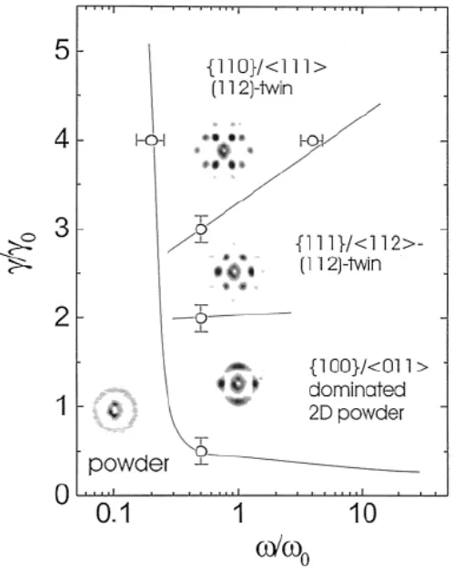
Figure 3.14 Phase diagram displaying texture development for normalized shear amplitude and angular frequency where normalized frequency (ω0) and shear amplitude (γ0) are 2 s-1 and 20%, respectively.134... 60 Figure 3.15 Compressive stress relaxation plots on a double logarithmic scale for SEBS gels at 250C and 15 wt% copolymer at different deformation (λ).135 (B) Stress relaxation rate [m = -d(log σ)/d(log t)] as a function of temperature for SEBS (87.3 Kg/mol with 32 % S) at 8.5 (), 11.2 (∆), and 17.5 wt% (○) and SEBS (260 Kg/mol with 30 % S) at 4.9 (◊) and 6.8 wt% (õ) at deformation 0.7.114... 61 Figure 3.16 TEM micrograph of SEBS TPEG with 30, 20, 10 wt% copolymer quenched from 180 to 00C.89... 63 Figure 3.17 TEM micrograph of an annealed SBM/oil blend of (50/50 g/g). (a) RuO2 stained gels showing hexagonally array of cylinders of M endblocks. (b) OsO4 stained gels showing both S and M cylinders. (c) Circle in the (b) zoomed here showing PMMA hexagon in the centre and dotted lines showing hexagon of S. (d) schematic illustration of proposed twinned hexagonal structure.103... 64 Figure 3.18 Schematic illustration of temperature dependent structure of PMMA triblock copolymer gels in alcohols.141... 66 Figure 4.1 In (A), the operational principle of a conventional elastomeric EAP before and after actuation. Development of a Maxwell stress (labeled) between oppositely charged compliant electrodes squeezes the elastomer, thereby causing lateral displacement of the specimen. The morphology of a midblock-swollen triblock copolymer that self-organizes into glassy micelles connected by a midblock network before and after actuation is schematically depicted in (B). A TEM image (scale marker = 50 nm) of a solvated copolymer system containing 10 wt% SEBS161, with the S-rich micelles selectively stained by the vapor of RuO4(aq), is included to confirm the existence of the micellar morphology in the inset of (B). 83
( ), 10 ( ), 15 ( ), 20 ( ), 25 ( ) and 30 ( ). The solid lines represent exponential fits to the data. 85
LIST OF TABLES
CHAPTER 1
1 Introduction
addition, a large uniaxial or biaxial prestrain (often >100%) is commonly required in conjunction with the use of dielectric EAPs to enhance their actuation performance2. Common dielectric EAP actuator are typically used in tube, rolled, bow, bowtie, frame-supported and laminated configurations that are designed to support the required prestrain.14,15 These prestrain fixtures occupy substantial space and weigh considerably more than the dielectric polymer films.15 Performance parameters of dielectric elastomer actuators, such as the elastic energy density, are consequently reduced by an order of magnitude or two due to overhead (e.g., packaging) or additional required structures associated with them.16 In addition, the performance of dielectric elastomers can vary with time since stress relaxation of the viscoelastic matrix eventually serves to release the initial prestrain applied.17 Furthermore, stress concentration located at the interface between the dielectric elastomer film and the rigid support limits the life span of these actuators. Until now, efforts to improve the electromechanical response of D-EAPs have been restricted to addition of fillers or design refinements15-17. There is hardly any published report on material development toward better electroactive behavior of polymers. Zhang et al. altered the actuation response of silicone from materials standpoint that is by changing the type and concentration of hardener18,19. Only silicone and polyurethane properties are modified, and these generally exhibit lower electromechanical response compared to acrylic1,2,13,16,19. Zhang et al. observed that variation of the hardener concentration has small effect on the dielectric constant of the silicones19. Superior electromechanical response was achieved with silicones of lowest modulus.
The research described here is aimed at developing EAP materials with widely tunable electromechanical properties and improved response at low electrical fields. The innovative approach involves use of thermoplastic elastomer gels whose properties can be tailored to a large extent by changing the composition of the homopolymers as well as that of the solvents.
because the papers are intended to be sufficiently independent. A short description of each is provided below to help readers navigate.
Chapter 1. Introduction to EAPs and outline of thesis.
Chapter 2. Includes review of pertinent literature. It gives detailed account of different EAPs: their principle of actuation, advantage, and limitations. Primary focus of this review is dielectric EAPs. Dielectric elastomers based on homopolymers are discussed in details here. In addition, important materials and performance parameters of D-EAPs are compared. This chapter has been accepted for publication in Soft Matter and is currently in press.
Chapter 3. Details of thermoplastic elastomer gels (TPEGs) is discussed here. Micellization of block copolymers and gel types (both physical and chemical gels) are discussed with particular emphasis on physical gels. Thermoplastic elastomer gels are broadly classified as styrenic and non-styrenic based gels. Styrenic gels are considered more relevant to the current work and are therefore discussed in more detail. This chapter will be submitted to Macromolecular Rapid Communication for publication.
Chapter 4. Describes the fabrication of tunable nanostructured electroactive polymers (ENPs). These ENPs are based on poly[styrene-b-(ethylene-co-butylene)-b-styrene] (SEBS) triblock copolymers. Tunability of ENPs is achieved by either selecting SEBS of different molecular weights or changing the copolymer fraction. Electromechanical behavior of ENPs is determined and compared with current dielectric elastomers. This chapter is slated to be published in Advanced Materials and is currently in press.
Chapter 6. Mechanical and electrical properties of ENPs of three different molecular weight is investigated and compared with acrylic foam. Mechanical properties of acrylic and ENPs are investigaed under tensile and compressive loading conditions. Compressive properties of ENPs are evaluated under various levels of in-plane prestrains . The ENPs are also evaluated for blocking stress under isometric conditions. This chapter has been submitted to Sensors and Actuators A for publication.
Chapter 7 Electromechanical behavior of SEBS triblock copolymers of three different molecular weights is explained. A comparison between both material and performance properties of ENPs is made as a function of molecular weights and copolymer fractions. Effect of midblock selective oil type on actuation behavior also presented. In addition, results of both electrical and mechanical cycling on ENPs are investigated. This chapter is submitted to Macromolecules for publication.
Chapter 8 Includes summary of the present study and recommendations for future work.
1.1 References
1. Bar-Cohen, Y. in Electroactive Polymer (EAP) Actuators as Artificial Muscles:
Reality, Potential, and Challenges (ed Bar-Cohen, Y.) (SPIE Press, Bellingham, WA,
2004).
2. Pelrine, R., Kornbluh, R., Pei, Q. & Joseph, J. High-Speed Electrically Actuated
Elastomers with Strain Greater Than 100%. Science 287, 836-839 (2000).
3. Zhang, S., Randall, C. A. & Shrout, T. R. Electromechanical properties in
rhombohedral bisco[sub 3]-pbtio[sub 3] single crystals as a function of temperature.
Jpn. J. Appl. Phys., Part 2 42, L1152 (2003).
4. Park, S. & Shrout, T. R. Ultrahigh strain and piezoelectric behavior in relaxor based
5. Zhang, Q. M. et al. An all-organic composite actuator material with a high dielectric
constant. Nature 419, 284-287 (2002).
6. Huang, C., Zhang, Q.M., deBotton, G. & Bhattacharya, K. All-organic
dielectric-percolative three-component composite materials with high electromechanical
response. Appl. Phys. Lett. 84, 4391-4393 (2004).
7. Chu,B., Zhou,X., Ren,K., Neese,B., Lin,M., Wang,Q., Bauer,F. & Zhang,Q.M. A
dielectric polymer with high electric energy density and fast discharge speed. Science
313, 334-336 (2006).
8. Baughman, R. H. Playing nature's game with artificial muscles. Science 308, 63-65
(2005).
9. Baughman, R. H. et al. Carbon nanotube actuators. Science 284, 1340-1344 (1999).
10.Berdichevsky, Y. & Lo, Y. H. Polypyrrole nanowire actuators. Adv. Mater. 18,
122-125 (2006).
11.Vozzi, G., Carpi, F. & Mazzoldi, A. Realization of conducting polymer actuators
using a controlled volume microsyringe system. Smart Mater. Struct. 15, 279
(2006).
12.Ha, S. M., Yuan, W., Pei, Q., Pelrine, R. & Stanford, S. Interpenetrating polymer
networks for high-performance electroelastomer artificial muscles. Adv. Mater. 18,
887-891 (2006).
13.Madden, J. D. W. et al. Artificial muscle technology: physical principles and naval
14.Pei, Q., Rosenthal, M., Stanford, S., Prahlad, H. & Pelrine, R.
Multiple-degrees-of-freedom electroelastomer roll actuators. Smart Mater. Struct. 13, N86-N92 (2004).
15.Pei, Q., Pelrine, R., Stanford, S., Kornbluh, R., Rosenthal, M., Meijer, K. & Full, R. J.
Multifunctional electroelastomer rolls and their application for biomimetic walking
robots. Proc. SPIE Int. Soc. Opt. Eng. 4698, 246-253 (2002).
16.Pons, J. L. Emerging Actuator Technologies A Micromechatronic Approach (Wiley,
Chichester, England , Hoboken, NJ, 2005), 2, p. 731.
17.Choi, H.R., Jung, K., Chuc, N.H., Jung, M., Koo, I., Koo, J., Lee, J., Lee, J., Nam, J.
& Cho, M. Effects of prestrain on behavior of dielectric elastomer actuator. Proc.
SPIE. 5759, 283-291 (2005).
18.Zhang, X., Löwe, C., Wissler, M., Jähne, B. & Kovacs, G. Dielectric Elastomers in
Actuator Technology. Adv. Eng. Mater. 7, 361-367 (2005).
19.Zhang, X. Q., Wissler, M., Jaehne, B. Broennimannm R.,& Kovacs, G. Effect of
Crosslinking, Prestrain and Dielectric Filler on the Electromechanical Response of a
New Silicone and Comparision with Acrylic Elastomer. Proc. SPIE. 5385, 78-86
CHAPTER 2
2 Dielectric Elastomers as Next-Generation Polymeric Actuators
2.1 Abstract
Due to their versatile properties, robust behavior, facile processability and low cost, organic polymers have become the material of choice for an increasing number of mature and cutting-edge technologies. In the last decade or so, a new class of polymers capable of responding to external electrical stimulation by displaying significant size or shape change has emerged. These responsive materials, collectively referred to as electroactive polymers (EAPs), are broadly classified as electronic or ionic according to their operational mechanism. Electronic EAPs generally exhibit superior performance relative to ionic EAPs in terms of actuation strain, reliability, durability and response time. Among electronic EAPs, dielectric elastomers exhibit the most promising properties that mimic natural muscle for use in advanced robotics and smart prosthetics, as well as in haptic and microfluidic devices. Elastomers derived from homopolymers such as acrylics and silicones have received considerable attention as dielectric EAPs, whereas novel dielectric EAPs based on selectively swollen nanostructured block copolymers with composition-tailorable properties have only recently been reported. Here, we provide an overview of various EAPs in terms of their operational mechanisms, uses and shortcomings, as well as a detailed account of dielectric elastomers as next-generation actuators.
2.2 Introduction to Electroactive Polymers
examples of both sensors and transducers.2 A sensor is a material or device that is capable of monitoring changes in a specific system parameter without altering the parameter, whereas a transducer transforms energy from one form to another. More specifically, EAPs behave as actuators since they convert electrical energy into mechanical energy much in the same fashion as an electric motor can be used to generate torque. Vast improvements in actuator performance are becoming increasingly important in growing fields such as mechatronics, microrobotics, microfluidics and bionics so that high efficiencies at small scales, high power-to-weight ratios and large degrees of compliance can be ultimately realized.5-7
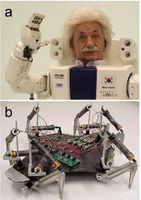
Figure 2.1 Contemporary examples of state-of-the-art robotic systems: (a) Albert Hubo
designed on the basis of hydraulics by KAIST and Hanson Robotics, Inc., (adapted from ref. 10 and used with permission from IEEE) and (b) FLEX 2 designed on the basis of electroactive polymers (EAPs) by SRI International (reprinted from ref. 67 and used with permission from SPIE).
induce actuation. Similarly, EACs are effective as compact, rapidly responsive materials, but they offer relatively little mechanical actuation (< 1% strain) and are typically fragile and expensive.7,13 A comparison among EAC, SMA and EAP properties has been reported by Bar-Cohen2 and is reproduced in Table 2.1. Since EAPs encompass a broad range of materials,1,2 they are routinely divided into two general categories on the basis of their physical state or actuation mechanism: ionic (or wet), wherein the EAPs may require the presence of a liquid medium to function by ion transport, and electronic (or dry), wherein the EAPs intrinsically actuate due to Coulombic forces.2 In the following sections, both EAP categories will be explored on the bases of mechanism and merit.
2.3 Ionic EAPs
In this section, three important types of ionic EAPs — carbon nanotubes (CNTs), conductive polymers (CPs) and ionic polymer-metal composites (IPMCs) — are introduced. In some cases, these materials are more accurately described as either nanostructured carbons (without the presence of a macromolecular species) or hybrid organic/inorganic materials composed of nanoscale particulates dispersed within a continuous polymeric matrix. The latter type of EAP may likewise be considered a polymer nanocomposite, depending on the characteristic size of the particulates employed.14 Details regarding other ionic EAPs (e.g., electrorheological fluids and ionic polymer gels) may be found elsewhere.1,2,15,16
2.3.1 Carbon nanotubes (CNTs)
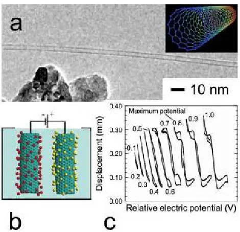
schematic of an isolated SWNT are shown for illustrative purposes in Fig. 2.2a. Even though CNTs exhibit a wide array of interesting properties ranging from gas storage to molecular catalysis, our focus in this work is restricted to the efficacy of CNTs as actuators. Electrical activation3 of CNTs is based on double-layer charge injection in which individual CNTs or CNT macrostructures (usually in the form of sheets) are immersed in an electrolyte solution, and a potential is applied between the CNTs and a counter electrode, as depicted in Fig. 2.2b. Ions residing in a CNT attract oppositely charged electrolyte ions on the outer CNT surface, which induces a rearrangement of the CNT electronic structure and accompanying Coulombic forces. Taken together, these factors yield a dimensional change in the CNT.
Table 2.1 Comparison of various inorganic and organic electroactive materials.a
Property EAC SMA EAP
Actuation strain (%) 0.1 − 0.3 < 8% > 1 (up to > 200)
Blocking force (MPa) 30 − 40 ~700 0.1 − 3
Actuation speed magnitude (s) 10−6− 1 1 − 102 10−6− 102
Mass density (g/cm3) 6 − 8 5 − 6 0.9 − 2.5
Drive voltage (V) / field (V/μm) 50 − 800 — 2 − 7 / 10 − 150
Consumed power magnitudeb (W) 1 1 10−3
Fracture toughness Fragile Elastic Elastic, resilient a Reproduced with minor alteration from ref. 2.
b Power consumption is based on devices that are driven by the actuators.
Figure 2.2 Demonstration of single-wall carbon nanotubes (CNTs) as electroactive materials. High-resolution transmission electron microscopy (HRTEM) image of a lone CNT (adapted from ref. 21 and used with permission from Springer) and an illustration of a single-wall CNT(reprinted from en.wikipedia.org/wiki/Wikipedia:Featured_picture_candidates/ February-2006 and used with permission) are displayed in (a). In (b), the mechanism by which CNT-based actuators operate is illustrated (reprinted from ref. 11 with permission from Elsevier). In (c), experimental data confirm that electrically-driven CNT "paper" (15 m thick) can bend a polymer film measuring ~0.2 mm thick (adapted from ref. 4 and used with permission from the American Association for the Advancement of Science).
SWNTs) and low mass production, ongoing efforts25,26 designed to grow and harvest highly oriented CNTs into designer yarns and sheets keep this actuator technology on the research forefront. Of particular interest is the use of CNT actuators as active noise and vibration reduction materials at low frequencies.3,4
2.3.2 Conductive polymers (CPs)
density/cycle, examples of which include catheters, as well as automotive and prosthetic devices.
2.3.3 Ionic polymer-metal composites (IPMCs)
Several studies27-29 have demonstrated that ionic polymer-metal composites, also referred to as IPMCs, are ideally suited as soft actuators for bending and sensing applications. The materials comprising this class of EAPs are routinely described as composite laminates, each consisting of a thin (200 - 300 μm), water-swollen ion exchange membrane with thin metal (Pt, Pd, Ag or Au) or carbon electrodes plated on both faces, as illustrated in Fig. 2.3a. Examples of suitable ion exchange membranes include perfluorinated ionomers, such as Nafion® and Flemion® with anionic-terminated side groups, or polystyrene ionomers with anionic-substituted phenyl rings.2 Prior to application of an electric potential, ion clustering occurs uniformly throughout the IPMC, because the solvated polymer matrix consists of a hydrophobic polymer backbone and hydrophilic anionic side groups in the presence of water. In the case of IPMC actuators, the polymer matrix is normally negatively charged, in which case counterions (i.e., cations) are introduced into the matrix. The mobile cations initially aggregate as clusters in discrete pockets of water throughout the membrane. As an electrical potential is applied across the IPMC actuator, however, the cations spatially redistribute as they diffuse toward the cathode, thereby forming a cation-rich layer along the cathode side and depleting cations from the anode side (cf. Figs. 2.3b and 2.3c).
Figure 2.3 Schematic diagram showing the operational principle of IPMCs. Prior to actuation, the aqueous IPMC is flat (a). Application of an electrical potential promotes migration of cations, thereby causing the IPMC to curve or bend (b). The system eventually adjusts to the applied electrical potential (c) and can return to (a) upon removal of the potential (reprinted from ref. 3 with permission from IEEE).
2.4 Electronic EAPs
In the previous section, the operational mechanisms and potential applications associated with ionic EAPs have been explored. This section now focuses on EAPs that respond directly, without the use of added charge carriers (e.g., electrolyte solutions), to an external electric field. Such materials, referred to as electronic EAPs, do not require mass transport and are therefore not diffusion-limited. The consequence is that electronic EAPs, commonly distinguished on the basis of their actuation mechanism as either electrostrictive (ferroelectric polymers) or electrostatic (dielectric elastomers), generally possess fast response times. These two EAP categories are discussed below.
2.4.1 Ferroelectric polymers
Electrostriction occurs when the dielectric properties of a material change with strain.1,2 Examples of electrostrictive polymer actuators include ferroelectric macromolecules such as polyvinylidene fluoride (PVDF), poly(vinylidene fluoride-co-trifluoroethylene) (PVDF-TrFE), polyvinyl fluoride (PVF), odd-numbered nylons (with an odd number of carbon atoms between amide groups) and polyurethane.1,2 One of the most extensively investigated materials, PVDF, as well as its copolymers and terpolymers, is semicrystalline, composed of crystals dispersed in an amorphous, molten matrix. Reported30 values of the normal melting and glass transition temperatures for commercial-grade PVDF are 176 and 60°C, but copolymerization of PVDF commonly induces a reduction in these transition temperatures. Upon application of an external electric field, domains of amorphous polymer become polarized and align in the direction of the applied field. This field-induced polarization is permanent, remaining after cessation of the field.3 A molecular-level representation of field-induced actuation is provided for PVDF-TrFE in Fig. 2.4a, which depicts the all-trans (T) conformation constituting the β phase. The electromechanical response of PVDF-TrFE is attributed to a phase transformation from ferroelectric (all T) to paraelectric (a mixture of T and gauche, G).31 It is evident from this figure that the transformation to the α phase promotes a large change in the lattice constant, which has been experimentally confirmed by Tashiro et al.32 The large molecular strains induced by such a transition are often accompanied by relatively large strain hysteresis.
A terpolymer composed of PVDF-TrFE with a small quantity (~4 mol%) of chlorofluoroethylene (CFE, -CH2-CFCl-) has been found to exhibit superior electromechanical properties relative to the parent PVDF-TrFE copolymer. A thickness strain of 4.5% with a coupling efficiency of 55% has been achieved at a relatively low electric field (130 V/μm). Starting with an elastomer, Su et al.35 have chemically grafted polarizable sequences onto flexible polymer backbones to generate electrostrictive graft elastomers that can attain strains of ~4% upon actuation. In another strategy,36 the dielectric constant (ε) of the PVDF-TrFE copolymer has been greatly improved through the physical addition of a high-ε organometallic filler, namely, copper phthalocyanine (CuPc, with ε > 106). In this case, addition of 40 wt% CuPc, a highly planar compound (depicted in the inset of Fig. 2.4b), is observed to increase ε of the hybrid material from 40 to 225. The composition dependence of ε in a PVDF-TrFE copolymer modified with CuPc is shown in Fig. 2.4b. Bobnar et al.37 have likewise investigated a multicomponent composite consisting of PVDF-TrFE-CFE modified with CuPc, whereas Huang et al.38 have studied the electromechanical behavior of PVDF-TrFE-chlorotrifluoroethylene (CTFE) terpolymer modified with different concentrations of PANi (included for comparison in Fig. 2.4b).
Generally speaking, the advantages of such electrostrictive EAPs is that moderate strains (up to ~7%) can be achieved under low-frequency fields, but they can also be operated at frequencies in excess of 100 kHz.3
They can likewise generate high stresses1 (ca. 45 MPa) due to their high Young's modulus34 (> 0.4 GPa) and thus produce higher energy densities relative to piezoelectric ceramics.1 A severe drawback of electrostrictive EAPs is the high voltage (> 1 kV) or, alternatively, electric field (~150 V/μm) required for actuation. Due to the relatively high strains that are routinely achieved with these materials, surface electrodes tend to fatigue, and the EAPs show signs of considerable hysteresis, upon cycling.2
2.4.2 Dielectric elastomers
to the opposing surfaces of a thin elastomeric film.39-42 This attraction induces a compressive stress, the magnitude of which is dictated by the magnitude of the electric field (E) and ε. The level of corresponding strain achieved upon actuation, on the other hand, depends on Y. To ensure high actuation and cyclic displacement, these EAPs must (i) possess shape memory due to chemical or physical cross-linking, (ii) be flexible with a relatively low Y and (iii) possess a moderate-to-high dielectric constant (typical ε values range from ca. 3 to 7).2,3
with Eq. 3, whereas the dashed and dotted lines (power-law regressions to the data) deviate from this expected behavior and thus serve only as guides for the eye.
Table 2.2 Common electrical and mechanical properties of homogeneous D-EAPs.a
Elastomer Dielectric constant, ε Modulus, Y Reference(s)
(evaluated at 1 Hz) (MPa)
Fluoroelastomerb 13 2.5 43
Polyurethanec 7.0 17 43
Fluorosiliconed 6.9 0.50 43
Acrylice 4.8 1.0 − 3.0 39
0.80 65
0.50 66
Polybutadienef 4.0 1.7 43
Siliconeg 3.3 − 3.7 0.35 − 0.56 66
(Silicone-C)h 2.8 1.0 49
(Silicone-H)i 2.8 0.13 49
Polyisoprene 2.7 0.85 43
a Values are expressed to two significant figures for consistency. b LaurenL143HC. c Deerfield PT6100S.
d Dow-Corning 730. e 3M VHB 4910. f Aldrich PBD. g Dow-Corning DC3481. h NuSil CF19-2186.
i Dow-Corning HS3.
following sections) are provided in Table 2.2. Introduction of polar functionalities along the polymer backbone generally tends to increase the value of , but does not necessarily ensure that the electrical actuation response will be improved. Accompanying changes in Y (due to the extent of cross-linking) and chain entanglement, as well as the propensity for specific inter/intramolecular interactions, may adversely affect the ability of an elastomer to respond to electrical stimulation. Pelrine et al.39 have reported that a commercial acrylic elastomer with moderate values of and Y can exhibit very high displacements when subjected to an external electric field. While a large number of elastomers derived from homopolymers (e.g., silicones,39 fluoropolymers43 and natural or synthetic rubber43) have been evaluated as D-EAPs, this acrylic elastomer has set the benchmark against which the performance efficacy of this family of materials is commonly assessed. Recent efforts41,42 have demonstrated that electro¬active nanostructured polymers (ENPs) composed of a microphase-separated triblock copolymer in a nonpolar midblock-selective solvent can likewise achieve high actuation strains at much lower electric fields than the acrylic elastomer. A detailed description of each of these materials is provided in a later section.
2.5 Actuation mechanism
relaxation and adhesive failure over time. Some D-EAPs have recently been found42 to exhibit adequate electrical actuation without pre-strain.
Figure 2.5 Schematic illustration showing the operational principle of D-EAPs. Prior to actuation, the elastomer film of initial thickness z0 is coated on each side with a compliant electrode. An applied electric field promotes attraction of the oppositely charged electrodes, thereby introducing a compressive Maxwell stress ( M) along the transverse (z) direction. Actuation is normally measured in terms of the lateral (in-plane) dimensional change, and the blocking force along the y-direction (Fy), for example, is identified.
2.6 Actuation characteristics
The key parameters that are commonly employed to characterize actuators must be fully understood prior to a detailed comparison of D-EAP actuators. It is important to recognize that, despite their attractively large actuation strains, high energy densities, fast response times and high coupling efficiencies, not all D-EAPs may provide the best performance required in all actuator applications. For this reason, a systematic description of the metrics needed to evaluate actuation efficacy is required. In this section, we present and discuss the common characteristic parameters used to describe D-EAP performance.
2.6.1 Actuation stress and blocking force
like charges along each electrode. According to Pelrine et al.,39 the Maxwell stress acting along z can be expressed as
σM = εεoE2 (1)
where εo is the permittivity of free space. Equation 6 establishes that the electric field-induced normal stress introduced during actuation is proportional to the square of the applied field and the dielectric constant of the D-EAP, which distinguishes D-EAP actuators from other electrostatic materials because ε of a polymer can be easily altered (by chemical or physical means) to increase σM without increasing the operating voltage. Along a lateral dimension, the blocking force constitutes the force required to return a fully energized actuator to zero displacement. In other words, it is the force generated by a linear actuator under the constraint of constant length. Kofod et al.45 have derived a relationship between the blocking force along the y-direction (Fy) and other relevant actuator attributes for D-EAPs, viz.,
Fy = (x0z0/αy)εεoE2 (2)
where αy (= y/y0) is the film displacement in the y-direction, while the orthogonal lateral dimension (x0) is held constant. The blocking stress (σB) is therefore given by Fy/Ay, where Ay is the cross-sectional area over which Fy acts (cf. Fig. 2.5). Spinks et al.46 have examined the effect of preload tension on Fy in PPy ionic actuators and provide an analysis by which to explain their observation that Fy decreases with increasing preload tension.
2.6.2 Actuation displacement
since published reports tend to compare the actuation performance of different EAPs on the basis of strain without precisely delineating the type of actuation strain actually measured. Comparisons must therefore be made with caution, since areal or in-plane strains are typically an order or magnitude greater than transverse (or thickness) strain.39,41
2.6.2.1 Transverse or thickness strain
This actuation strain reflects a dimensional change in the thickness direction of an EAP film due to the normal pressure induced by an electrostatic Maxwell stress or electrostriction or combination of both.43 Because D-EAPs, in particular, significantly change their dimensions upon electrical stimulation, this strain establishes a characteristic signature of a given D-EAP material, and it is used to determine many other important actuation parameters. Since bulk D-EAP films evaluated for actuation efficacy are usually thin (often on the order of 1 mm), direct measurement of strain along the z-direction can be challenging. For this reason, the thickness, or transverse, strain is routinely calculated from experimental measurements of in-plane (lateral) actuation strain under the assumption of isochoric deformation. Yang et al.,47 however, have experimentally measured the transverse strain of silicone and polyurethane elastomers using laser Doppler interferometer. In most D-EAPs, the transverse strain, denoted as sz where sz is defined as (z − z0)/z0, arises due to the Maxwell stress discussed earlier. If the strain is sufficiently small (< 20%) so that the deformation due to actuation can be presumed to be linearly elastic, Hooke's law in compression (σM = − Ysz) can be used to directly relate the transverse strain to the applied electric field:
sz = −εεo E2/Y (3)
transverse strain are related by (1 + sx)(1 + sy)(1 + sz) = 1. If the actuation-induced in-plane deformation is isotropic, sx = sy = sxy and
sz = (1 + sxy)−2− 1 (4)
In the case of non-piezoelectric materials, such as polyurethane elastomers, the actuation strain along the thickness direction can be a consequence of either an electrostriction effect (i.e., direct coupling between molecular polarization and the mechanical response of the material) or an electrostatic Maxwell stress or a combination of both. According to Zhang et al.,48 the transverse strain due to electrostriction (se) is related to the polarizability (p) of an EAP through |se| = qp2, where q is the electrostrictive coefficient. For a linear dielectric medium, p = εo (ε− 1)E so that
|se| = qεo2(ε− 1)2E2 (5)
2.6.2.2 In-plane (lateral) and bending strains
Figure 2.6 Circular experimental setup used to measure the electromechanical behavior of D-EAPs in the presence of an electric field and corresponding optical images. An elastomeric film is commonly subjected to a mechanical prestrain and subsequently fixed to a frame prior to coating the active area on both film surfaces with a compliant electrode. Actuation upon electrical stimulation results in an increase in the active area, which is digitally measured and quantified.
2.7 Actuation performance
The energy or power generated upon electrical stimulation also constitutes crucial performance metrics of EAPs. In this section, key actuator parameters such as the strain energy density and coupling efficiency are introduced and discussed. The strain energy density for D-EAPs is defined3,39 as the amount of work generated in one actuation cycle per unit volume of actuator, exclusive of overhead peripherals, such as electrolytes, power supplies, counter electrodes and packaging. It can be derived directly from experimentally measured quantities, such as the electrostatic stress and transverse strain discussed in previous sections. At small actuation strain levels typically encountered by ferroelectric EAPs (< 10% strain) or D-EAPs actuated under low electric fields, the stored elastic energy (ES) is given by −σMsz/2 on a unit volume basis. In terms of material properties, ES can be rewritten as
ES = Ysz2/2 (6)
If large actuation strains are generated, Pelrine et al.39 propose a description for the elastic energy density based on the assumptions of isochoric deformation and constant electrostatic stress (σM). Under these conditions, Az relates to sz by x0y0/(1 + sz), and the corresponding elastic energy density (EL) can be obtained by integrating the compressive force over the transverse displacement and putting the result on a unit volume basis. The closed-form analytical result is
EL = −σM ln(1 + sz) (7)
does not change upon activation. For elastomeric materials under isochoric conditions, the change in electrical energy upon actuation is approximately equal to the work output, in which case K2 can be conveniently written as43
K2 = − 2sz − sz2 (8)
Materials with a low K2 value are not desirable as actuators because they require a large amount of electrical energy relative to the amount of work that can be harnessed.
2.8 Homogeneous dielectric elastomers
As mentioned earlier, a wide variety of elastomers derived from chemically cross-linked homopolymers have been investigated as D-EAPs. Specific examples include acrylics, silicones (including fluorinated silicones), polyurethanes, fluoroelastomers, ethylene-propylene rubber (EPR), polybutadiene (PB) and polyisoprene (PI, natural rubber). Relative to other EAPs, these network polymers must inherently possess low Y and high ε to maximize σM and sz by Eqs. 1 and 3, respectively. Although the polyurethane, fluorosilicone and fluoroelastomer D-EAPs typically have a higher ε compared to the silicones and acrylics, the acrylics and silicone elastomers exhibit superior actuator performance relative to other D-EAPs, as well as EAPs in general. In fact, the maximum efficiency afforded by these materials, discussed in detail below, compares favorably with other types of electroactive materials, including inorganic ones.
2.8.1 Acrylic elastomers
before breaking.44 It is also reported2 to be thermally stable from -10° to 80°C. While this acrylic elastomer is undoubtedly a low-modulus material, reported values of its elastic modulus vary considerably, ranging from 1-3 MPa according to Madden et al.3 to much less than 1 MPa.41 This variability may reflect material anisotropy or defects, as well as differences in the mode of testing (i.e., tension versus compression), as well as the method (i.e., direct tension/compression versus inflated diaphragm) by which the elastic modulus is measured. Unfortunately, important details such as these are not always and consistently documented in the literature. Mechanical measurements conducted in our laboratory yield a tensile modulus of 0.20 MPa and a compressive modulus of 0.27 MPa. This acrylic elastomer has been reported to exhibit an ultrahigh areal actuation strain of 158% and transverse strains up to ca. 60-70%, depending on the level of pre-strain applied in the in-plane direction, as indicated in Table 2.3. A blocking stress of 7.2 MPa and a corresponding elastic energy density of 3.4 MJ/m3 constitute the highest actuation metrics reported39 to date for D-EAPs. When such values are provided, however, care must be exercised in performing a comparative analysis among D-EAPs. Recall from Eq. 1 that the electrostatic (Maxwell) stress is directly proportional to E2 and that E is inversely proportional to film thickness. While most reports of D-EAP actuation calculate E relative to the initial film thickness, others39 use the instantaneous E arising from the true film thickness upon actuation. This difference will obviously change numerical values, but the benchmark actuation performance of the acrylic elastomers remains intact. In fact, these D-EAPs also possess the highest coupling efficiency (~90%) of all D-EAPs derived from homopolymers (cf. Table 2.3).
2.8.2 Silicone elastomers
applied (cf. Table 2.3). In fact, Yang et al.51 have demonstrated that the transverse strain achieved depends delicately on the geometry of the actuator.
Other important considerations governing actuation performance include (i) the chemistry and molecular weight of the polysiloxanes to be cross-linked, (ii) the chemistry (functionality) by which the macromolecules are cross-linked and (iii) the extent to which the macromolecules are cross-linked. 52 For a given silicone and cross-linking agent, only (iii) remains variable, but variation in cross-link density can strongly affect the elastic modulus and, hence, actuation performance. Therefore, caution must be exercised in maintaining systematic preparation conditions. Generally speaking, silicones exhibit marginally lower maximum electromechanical coupling efficiencies (63-79%) but greater thermal stability (from -65 to 240°C) than acrylic elastomers,44 and they tend to be less sensitive to environmental degradation.44 More importantly, though, they are more biocompatible than most carbon-based polymers53 and are therefore ideally suited for actuation applications at the human-machine interface (e.g., smart prosthetics).
2.9 Nanostructured dielectric elastomers
(Details of this section are presented in Chapter 3 and Chapter 4)
MPa (Table 2.3) and an electromechanical coupling efficiency of 21% upon electrical stimulation.
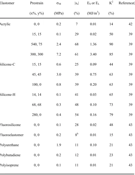
Table 2.3 Common electrical and mechanical properties of homogeneous D-EAPs.a
Elastomer Prestrain σM |sz| ES or EL K2 Reference(s)
(x%, y%) (MPa) (%) (MJ/m3) (%)
Acrylic 0, 0 0.2 7 0.01 14 42
15, 15 0.1 29 0.02 50 39
540, 75 2.4 68 1.36 90 39
300, 300 7.2 61 3.40 85 39
Silicone-C 15, 15 0.6 25 0.09 44 39
45, 45 3.0 39 0.75 63 39
100, 0 0.8 39 0.20 63 39
Silicone-H 14, 14 0.1 41 0.03 65 39
68, 68 0.3 48 0.10 73 39
280, 0 0.4 54 0.16 79 39
Fluorosilicone 0, 0 0.1 28 0.02 48 43
Fluoroelastomer 0, 0 0.2 8b 0.01 15 43
Polyurethane 0, 0 1.9 11 0.10 21 43
Polybutadiene 0, 0 0.2 12 0.01 23 43
Polyisoprene 0, 0 0.1 11 0.01 21 43
Figure 2.7 TEM image of an ENP composed of a microphase-separated SEBS triblock copolymer swollen with a midblock-selective oligomeric oil. The micellar morphology in this 10/90 w/w SEBS/oil system consists of swollen EB midblocks that form a molecular network stabilized by glassy S micelles, which appear electron-opaque (dark) due to selective staining with the vapor of RuO4(aq). The copolymer network illustrated in the inset displays only bridged midblocks for the sake of clarity (the midblocks may also form loops and dangling ends).
The highest value of K2 measured from these materials, collectively referred to as electroactive nanostructured polymers (ENPs) to distinguish their structure relative to conventional D-EAPs, is 92%, which exceeds that of the acrylic elastomers. Moreover, unlike the chemically cross-linked homogeneous elastomers discussed earlier, these highly elastic and reprocessable materials (i) undergo little actuation hysteresis (< 15%) upon cycling (i.e., 100 cycles to 48-60% of the breakdown electric field)41 and (ii) exhibit acceptable actuation without the need for mechanical pre-strain.42
2.10 Comparison of EAPs
displacement, in-plane actuation strain is presented as a function of voltage for various EAPs in Fig. 2.8a and as a function of electric field primarily for D-EAPs in Fig. 2.8b. For completeness, the transverse actuation strains corresponding to the D-EAPs in Fig. 2.8b are likewise provided in Fig. 2.8c. Figure 2.8a clearly shows that the ionic EAPs require the lowest applied voltages, whereas the electronic EAPs actuate at high voltages (> 1 kV). While this difference is broadly considered to be one of the practical limitations of electronic EAPs, Pelrine et al.39 have suggested that compact voltage amplifiers could be designed to solve this problem. The requirement for high voltage may even be considered advantageous because less current is needed to produce a desired power level, thereby allowing efficient electrical energy transmission through thin wires and thus reducing concern associated with contact resistance. In all fairness, however, it must also be recognized that the voltage to be applied for actuation depends on specimen thickness, since the actuation performance of electronic EAPs depends on electric field.
This dependence is evident in Figs. 2.8b and 2.8c, which together confirm that the acrylic elastomer, some silicone elastomers and the copolymer-based ENPs discussed in the prior section exhibit the highest in-plane and transverse strains upon electrical stimulation (details of ENPs are presented in Chapters 3 and 4). These materials are attractive because of their desirable attributes such as light weight, mechanical resilience, rapid response and high energy density.
Other important comparative metrics include the blocking stress and energy density, which are displayed as a function of actuation strain in Fig. 2.9. In this figure, the ionic CP and electrostrictive ferroelectric polymer (PVDF-TrFE) are seen to exhibit the highest blocking stresses (ca. 10 to more than 100 MPa) of the EAPs at relatively low strains, whereas the acrylic elastomer enjoys both a high blocking stress (between ~1 and 10 MPa) and a high actuation strain (> 100%). The straight lines with a slope of −1 are identified by discrete energy density values and connect actuator classes possessing comparable volumetric stroke work.7 Included for comparison in Fig. 2.9 are the performance metrics for natural muscle, which is most closely emulated by the IPMC ionic EAP, as well as the dielectric silicone and ENP elastomers. Actuators located on the right side of this figure can provide a high stroke (large actuation displacement), thereby making them suitable candidates for (i) biomimetic applications including artificial muscle and microrobotics and (ii) microfluidic and haptic devices requiring lateral or transverse extension. It should be noted here that hydraulic actuators, which exhibit similar or slightly larger actuation strains than natural muscle with considerably higher blocking stresses (~10-100 MPa), have been used extensively in robotics (cf. Fig. 2.1).1-3,62 However, the size and weight of the overhead peripherals (i.e., pumps, piping and supports) required for such actuators preclude their use in small-scale and lightweight devices.
response times of CPs and D-EAPs are on the order of milliseconds, in marked contrast to human muscle and SMAs, which require at least one and over two orders of magnitude more time to fully actuate.
Figure 2.9 Dependence of blocking stress on actuation strain for various electroactive materials and systems: inorganic (green), ionic and ferroelectric EAPs (black) and D-EAPs (red). The dotted diagonal lines correspond to different energy densities (blue, labeled), and the red area signifies the characteristics of human muscle. (Modified from the SRI International document at http://ndeaa.jpl.nasa.gov/nasa-nde/lommas/eap/actuators-comp.pdf and used with permission).
2.11 Technological opportunities
variation in optical density or refractive index as the actuator thickness changes with applied electrical field. Moreover, the high actuation strain levels and energy output of D-EAPs can be exploited to construct diaphragms capable of generating large out-of-plane deflection and correspondingly large volume displacements suitable for microfluidic pumps and valves, as well as loudspeakers and responsive haptic (e.g., refreshable Braille) displays.2,11,40 Other applications of D-EAPs include sensors, motors and even a heel-strike generator that operates in reverse fashion to produce electricity from compressive deformation. Recently, D-EAPs have been fabricated64 into prototype fibers that can eventually be used in active textiles or in bundles to emulate natural muscle. As previously pointed out, D-EAPs constitute excellent artificial muscle candidates for biologically inspired robots, animatronics and responsive prosthetics, and prototype devices based on D-EAPs include a smart pill (i.e., a tube-like structure that travels like an inchworm inside the gastrointestinal tract), multi-legged robots and bird-like MAVs.2,11,40
2.12 Summary
copolymers with and without an extender solvent (i.e., ENPs and polyurethanes, respectively), have shown the most promising combination of mechanical and electrical actuation properties. Compared to other EAPs, the D-EAPs can produce very high actuation strains (> 200%) upon application of an external electric field due primarily to the development of an electrostatic (Maxwell) stress. Furthermore, D-EAPs possess fast response times, high energy densities and high electromechanical efficiencies. Although all D-EAPs require high electric fields to achieve maximum actuation (which undoubtedly poses a practical challenge), these materials nonetheless constitute viable and attractive alternatives for use in emerging microrobotic, aerospace, automotive, haptic, biomimetic and microfluidic technologies.
2.13 Acknowledgments
Support for this work has been provided by the U. S. Department of Commerce through the National Textiles Center.
2.14 Related websites
The following websites provide movie clips of electrical devices that could or already benefit from advances in EAP design and actuation performance:
http://eap.jpl.nasa.gov
http://www.artificialmuscle.com
http://www.sri.com/esd/automation/actuators.html http://www.hansonrobotics.com
http://www.unm.edu/~amri
http://www.electropolymertechnology.com/web1.htm
2.15 Notes
Technology & Management and ‡Chemical & Biomolecular Engineering, North Carolina State University, Raleigh, NC 27695, USA).
2.16 References
1. J. L. Pons, Emerging Actuator Technologies: A Micromechatronic Approach, Wiley, NJ,
2005.
2. Y. Bar-Cohen (Ed.), Electroactive Polymer (EAP) Actuators as Artificial Muscles:
Reality, Potential, and Challenges, SPIE Press, Bellingham, WA, 2004.
3. J. D. W. Madden, N. A. Vandesteeg, P. A. Anquetil, P. G. A. Madden, A. Takshi, R. Z.
Pytel, S. R. Lafontaine, P. A. Wieringa and I. W. Hunter, IEEE J. Ocean. Eng., 2004,
29, 706-728.
4. R. H. Baughman, C. Cui, A. A. Zakhidov, Z. Iqbal, J. N. Barisci, G. M. Spinks, G. G.
Wallace, A. Mazzoldi, D. De Rossi, A. G. Rinzler, O. Jaschinski, S. Roth and M.
Kertesz, Science, 1999, 284, 1340-1344.
5. I. R. Sinclair, Sensors and Transducers, Butterworth-Heinemann, Oxford, 2001.
6. M. Fremond and M. Miyazaki., Shape Memory Alloys, Springer, New York, 1996.
7. J. E. Huber, N. A. Fleck and M. F. Ashby, Proc. R. Soc. London Ser. A, 1997, 453,
2185-2205.
8. Y. Bar-Cohen, Expert Rev. Med. Devices, 2005, 6, 731-740.
9. Y. Bar-Cohen (Ed.), Biomimetics Biology Inspired Technologies, Taylor & Francis,
Boca Raton, FL, 2005.
10. J.-H. Oh, D. Hanson, W.-S. Kim, Y. Han, J.-Y. Kim and W. Park, Proc. 2006 IEEE/RSJ
11. T. Mirfakhrai, J. D. W. Madden and R. H. Baughman, Mater. Today, 2007, 10, 30-38.
12. V. H. Ebron, Z. W. Yang, D. J. Seyer, M. E. Kozlov, J. Y. Oh, H. Xie, J. Razal, L. J.
Hall, J. P. Ferraris, A. G. MacDiarmid and R. H. Baughman, Science, 2006, 311,
1580-1583.
13. A. Moulson and J. Herbert, Electroceramics, Chapman & Hall, London, 1995.
14. J. D. Nam, H. R. Choi, Y. S. Tak and K. J. Kim, Sens. Actuators A, 2003, 105, 83-90.
15. M. Parthasarathy and D. J. Klingenberg, Mater. Sci. Eng. R, 1996, 17, 57-103.
16. M. Doi, M. Matsumoto and Y. Hiroset, Macromolecules, 1992, 25, 5504-5511.
17. S. Iijima, Nature, 1991, 354, 56-58.
18. P. J. F. Harris, Carbon Nanotubes and Related Structures: New Materials for the 21st
Century, Cambridge University Press, Cambridge, 1999.
19. R. H. Baughman, A. A. Zakhidov and W. A. de Heer, Science, 2002, 297, 787-792.
20. S. Niyogi, M. A. Hamon, H. Hu, B. Zhao, P. Bhowmik, R. Sen, M. E. Itkis and R. C.
Haddon, Acc. Chem. Res., 2002, 35, 1105-1113.
21. Y. Zhang, Y. Li, W. Kim, D. Wang and H. Dai, Appl. Phys. A, 2002, 74, 325-328.
22. Y. L. Li, I. A. Kinloch and A. H. Windle, Science, 2004, 304, 276-278.
23. R. H. Baughman, Nat. Nanotech., 2006, 1, 94-96.
24. E. Smela and O. Inganäs, Science, 1995, 268, 1735-1738.
25. R. H. Baughman, Synth. Met., 1996, 78, 339-353.
26. L. Bay, K. West, P. Sommer-Larsen, S. Skaarup and M. Benslimane, Adv. Mater., 2003,
15, 310-313.
27. K. Kaneto, M. Kaneko, Y. Min and A. G. MacDiarmid, Synth. Met., 1995, 71,
28. B. J. Akle, M. D. Bennett and D. J. Leo, Sens. Actuators A, 2006, 126, 173-181.
29. S. Nemat-Nasser and Y. X. Wu, J. Appl. Phys., 2003, 93, 5255-5267.
30. B.-E. El Mohajir and N. Heymans, Polymer, 2001, 42, 5661-5667.
31. C. Huang, R. Klein, F. Xia, H. Li, Q. M. Zhang, F. Bauer and Z.-Y. Cheng, IEEE
Trans., 2004, 11, 299-311.
32. K. K. Tashiro, M. Takano, Y. Kobayashi, A. Chatani and H. Tadokoro, Ferroelectrics,
1984, 57, 297-326.
33. Q. M. Zhang, V. Bharti and X. Zhao, Science, 1998, 280, 2101-2104.
34. F. Xia, H. Li, C. Huang, M. Y. M. Huang, H. Xu, F. Bauer, Z.-Y. Cheng and Q. M.
Zhang, SPIE Proc. Ser., 2003, 5051, 133-142.
35. J. Su, J. S. Harrison, T. L. S. Clair, Y. Bar-Cohen and S. Leary, Mater. Res. Soc. Symp.
Proc., 1999, 600, 131-136.
36. Q. M. Zhang, H. Li, M. Poh, F. Xia, Z.-Y. Cheng, H. Xu and C. Huang, Nature, 2002,
419, 284-287.
37. V. Bobnar, A. Levstik, C. Huang and Q. M. Zhang, Phys. Rev. Lett., 2004, 92, Article
No. 047604.
38. C. Huang, Q. M. Zhang and J. Su, Appl. Phys. Lett., 2003, 82, 3502-3504.
39. R. Pelrine, R. Kornbluh, Q. Pei and J. Joseph, Science, 2000, 287, 836-839.
40. S. Ashley, Sci. Am., October 2003, 53-59.
41. R. Shankar, T. K. Ghosh and R. J. Spontak, Adv. Mater. (in press).
42. R. Shankar, T. K. Ghosh and R. J. Spontak, Macromol. Rapid Commun. (in press).
43. R. Pelrine, R. Kornbluh, J. Joseph , R. Heydt, Q. Pei and S. Chiba, Mater. Sci. Eng. C,
44. A. O’Halloran and F. O’Malley, in Topics in Bio-Mechanical Engineering (P. J.
Prendergast and P. E. McHugh, Eds.) Trinity Centre for Bioengineering & the National
Centre for Biomedical Engineering Science, Dublin & Galway, 2004, pp. 184-215.
45. G. Kofod, P. Sommer-Larsen, R. Kornbluh and R. Pelrine, J. Intell. Mater. Syst. Struct.,
2003, 14, 787-793.
46. G. M. Spinks, T. E. Campbell and G. G. Wallace, Smart Mater. Struct., 2005, 14,
406-412.
47. G. Yang, W. Ren, B. K. Mukherjee and J. P. Szabo, 14th IEEE Int. Symp., 2004,
237-240.
48. Q. M. Zhang, J. Su, C. H. Kim, R. Ting and R. Capps, J. Appl. Phys., 1997, 81,
2770-2776.
49. R. Kornbluh, R. Pelrine, Q. Pei, S. Oh and J. Joseph, SPIE Proc. Ser., 2000, 3987,
51-64.
50. A. Mazzoldi, F. Carpi and D. D. Rossi, Ann. Chim. Sci. Mater., 2004, 29, 55-64.
51. G. Yang, G. Yao, W. Ren, G. Akhras, J. P. Szabo and B. K. Mukherjee, SPIE Proc. Ser.,
2005, 5759, 134-143.
52. X. Zhang, C. Löwe, M. Wissler, B. Jähne and G. Kovacs, Adv. Eng. Mater., 2005, 7,
361-367.
53. D. Klee and H. Hocker, Adv. Polym. Sci., 1999, 149, 1-57.
54. I. W. Hamley, The Physics of Block Copolymers, Oxford University Press, New York,
1998.
55. I. W. Hamley (Ed.), Developments in Block Copolymer Science and Technology, Wiley,
56. M. Lazzari, G. Liu and S. Lecommandoux (Eds.), Block Copolymers in Nanoscience,
Wiley-VCH, Weinheim, 2007.
57. S. Jain and F. S. Bates, Science, 2003, 300, 460-464.
58. G. Holden, N. R. Legge, R. Quirk and H. E. Schroeder, H. E. (Eds.), Thermoplastic
Elastomers, 2nd ed., Hanser, Munich, 1996.
59. J. Su, Q. M. Zhang, C. H. Kim, R. Y. Ting and R. Capps, J. Appl. Polym. Sci., 1997, 65,
1363-1370.
60. J. H. Laurer, J. F. Mulling, S. A. Khan, R. J. Spontak and R. Bukovnik, J. Polym. Sci. B:
Polym. Phys., 1998, 36, 2379-2391.
61. G. J. van Maanen, S. L. Seeley, M. D. Capracotta, S. A. White, R. R. Bukovnik, J.
Hartmann, J. D. Martin and R. J. Spontak, Langmuir, 2005, 21, 3106-3115.
62. S. G. Wax and R. R. Sands, SPIE Proc. Ser., 1999, 3669, 2-10.
63. P. Sommer-Larsen, "Artificial Muscles" technical report, Risø National Laboratory,
posted at http://sitecoremedia.risoe.dk/research/artmus/Documents/MIC-ARTI.pdf,
1996.
64. S. Arora, T. Ghosh and J. Muth, Sens. Actuators A (in press).
65. W. Ma and L. E. Cross, Appl. Phys. A, 2004, 78, 1201-1204.
66. X. Q. Zhang, M. Wissler, B. Jaehne, R. Broennimann and G. Kovacs, SPIE Proc. Ser.,
2004, 5385, 78-86.
67. R. Pelrine, R. Kornbluh, Q. Pei, S. Stanford, S. Oh and J. Eckerle, SPIE Proc. Ser.,
CHAPTER 3
3 Thermoplastic Elastomer Gels –Reinventing the Wheel
3.1 Abstract
The ability of block copolymers to self assemble into different morphologies of nanometer length scale offers interesting properties. Triblock or multiblock copolymers in the presence of midblock selective solvent forms thermoplastic elastomer gels (TPEGs). This paper review the different types of TPEGs both styrenic and non-styrenic triblock copolymer based. In general, TPEGs are prepared with both saturated and unsaturated midblock containing triblocks. Properties of TPEGs are greatly influenced by chemical nature of the both midblock and endblocks.
3.2 Introduction
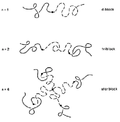
Figure 3.1 Schematic of (A-B)n block copolymers2.
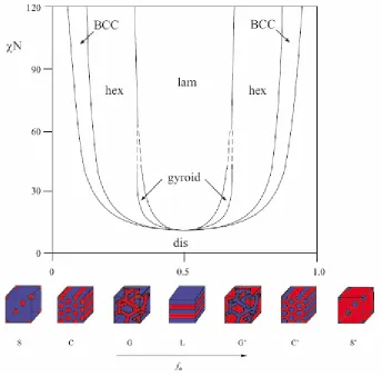
Nature and orientation of BCP nanostructured assemblies depend upon several factors such as molecular weight, composition, processing conditions, and block architecture2, 3, 5, 11-17. The morphological features of BCP are tunable either by addition of block-selective additives, such as homopolymer, solvents, cosurfactant (addition of second block copolymer)18-21 or resins, or alternatively by tailoring of the blocks chemically. Extent of segregation in BCP is expressed in terms of thermodynamic incompatibility, χN2, 16 (where χ is the Flory-Huggins interaction parameter, a temperature sensitive parameter and contains substantial enthalpic contribution and N denotes the number of repeat units along the copolymer backbone and dictate N-dependent translational and configurational entropy22). Figure 3.2 shows the phase diagram of a symmetric diblock copolymer melts in terms of χN and f (copolymer composition). When χN exceeds a critical value (χN)ODT (ODT is the order-disorder transition), BCP undergo a transition from a homogenous melt of chains to heterogeneous melt of ordered structure with a length scale of 5-500 nm23.
summarized in phase diagram parameters based on χN and f into three regimes: weak (χN ~10) and strong (χN >100) segregation limits and intermediate (χN ~10-100) segregation region (WSL, SSL, and ISR, respectively), details of which can be found elsewhere22, 26.
Figure 3.2 Phase behavior of symmetric diblock (A-B) copolymer based on self consistent mean field theory23, 24.
3.3 Networks
formation in polymers depend either on covalent bonding or physical intermolecular interactions between macromolecules and are termed as covalent and ‘entanglement networks’ (EN), respectively27, 29, 30. Topological interaction of polymer chains in the melt or solution form EN when the concentration and molecular weight (MW) product exceeds a critical MW. This act as ‘pseudogels’ at time scale shorter than the lifetime of the topological entanglements31. However, covalently cross-linked networks are formed by various ways such as cross-linking of high molecular weight linear chains, by endlinking reactant chains with a branching unit27, 31.
3.4 Gels
Gels are used since prehistoric times32; however, their definition is still matter of discussion. In 1926, Jordan Lloyd33 defined gels as “The colloidal state which is easier to recognize than to define”. In 1949, P. h. Hermans offered a more detailed definition as gels are coherent colloidal system having at least two components, possessing mechanical properties of solids where both the dispersed components and the dispersion medium are present continuously throughout the whole system34. Gels represent a state of matter in between solid and liquid exhibiting solid-like behavior when one of the components in solution forms a 3D network.
3.5 Gelation
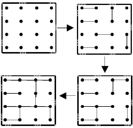
characterized by probability Pb42. Gelation occurs when Pb reaches a critical or threshold value Pc (Pb >Pc), there exist a single dot or molecule which is infinite in spatial extent i.e., connected dots traverse the entire grid41. Flory Stockmayer model is recognized as “bond-percolation” problem41, 43.
Figure 3.3 Schematic illustration of percolation theory of network formation.42
3.6 Classification of Gels
Gels are classified based on either their constituent phases, polymers or structurally. Table 3.1 shows the classifications of gels based on their constituents properties30. Flory44 classified gels on the basis of structure into four categories, catalogued in Table 3.2. Figure 3.4 displays the schematic of gels based on Flory’s classifications32. Alternatively, depending on the nature of the bond which forms the network, gels are classified either “chemical” or “physical”.
3.6.1 Chemical gels
therefore, have infinite relaxation times and an equilibrium modulus. Figure 3.5 illustrates the schematic of physical and chemical crosslinkings30.
Table 3.1Gels classifications*
Basis Type Examples-Solvent Materials
Hydrogel-water45, 46
poly(ethylene glycol-b-propylene glycol-b-ethylene
glycol) (Poloxamer), poly(ethylene glycol) / poly(D,L-lactic acid-co-glycolic
acid) block copolymers
Organogel-organic47, 48
Dibenzylidene sorbitol, 12-hydroxystearate,
2-amino-2-phenylethanol Solid-liquid
Alcogel-alcohol49 Phenol-Furfural
Xerogel-air50-52 Gelatin, tetraethoxysilane (TEOS) xerogel Constituent
phases and solvents
Solid-gas
Aerogel-air53-56 Silica, alumina, carbon aerogels
Natural gel Protein and polysaccharide gels30, 57
Pectin, agarose, agar, Fibrin clots
Synthetic gel
Organic polymer and
inorganic gels{58-60 Collagen based, TiO2 based Constituent
polymers
Hybrid gel
Polysaccharide/protein and synthetic polymer, Polymer andinorganic
material61, 62
polysaccharide-silica, TEOS and poly(ethylene glycol)
Table 3.2Flory’s structural classification of gels
Flory Category Statement Example Property
I
well-ordered lamellar structures, contain
gel mesophases
Soap gels and phospholipids, liquid
crystalline materials
Long range order
II covalent polymeric networks
Vulcanized rubber, elastic structure protein elastin,
vinyl-divinyl copolymers
Completely disordered
III
Polymer network formed through physical aggregation
Biopolymer gels gelatin, PVC,PVA
Predominantly disordered but with
ordered regions
IV Particulate
V2O5 gels, globular and fibrillar protein
gels
Disordered structure
Figure 3.5 Schematic illustrating chemical and physical crosslinking.30
3.6.2 Physical Gels