ISSN (Online): 2320-9364, ISSN (Print): 2320-9356
www.ijres.org Volume 2 Issue 8 ǁ August. 2014 ǁ PP.38-44
Independent Control Of Active And Reactive Powers From
DFIG By Logic Fuzzy
S. Mansouri* And A. Benatillah**
Labo EESI, Faculté des sciences et science de l’ingénieur, University of Adrar Street, Adrar, Algeria
Abstract – This paper presents the study and use by simulating the fuzzy logic control of asynchronous generator dual fuel in the production of electrical energy that the .for I prepared a study of the wind system and a model of the wind turbine was established by following the study and modeling of doubly fed asynchronous. Two types of vector control have been the subject of study in this work for independent control of active and reactive power: the direct and indirect control .la fuzzy PI control is introduced to increase the robustness of markers vis-à-screw parametric variation of the machine in the simulation results obtained were compared to the validated work articles cited in the bibliography.
Keywords: wind Power, DFIG, Vector control, fuzzy, PI.
I.
I
NTRODUCTIONElectrical energy is a key factor in the development and evolution of human societies as it is on the plane to improved living conditions on the development of industrial activities. It has become a form of vital energy through its flexibility and multiple business areas or she is expected to play a role more important.ces modes of production and the means of distribution partners are brought to undergo profound changes in the coming decades. [1]
Production of renewable energy has been extensively developed in recent years. Indeed, the modes of production based on the transformation of renewable energy for example wind, are expected to be increasingly used in the context of sustainable development. [2]
Wind power appears clearly prominently, not to replace conventional sources, but as nuclear energy. [3] This paper describes a study on the use of asynchronous tandem pilot through the power rotor sizes, integrated system in a wind machine.
The goal in this work is to provide those who follow instructions perfectly thanks to the fuzzy logic control [4,5,6,7] and reactive power. study the system isilluste illustrated
fig.1. diagram of the system studied [8]
II.
Modeling system:
A- Modeling of the wind turbine:The power produced by the Pt éolenne expressed as following:
) β , λ ( cp ν3 R 2 ρ 2 1 =
pt (1) the torque and power in function of the speed of the axis [9]
ωt ) β , λ ( cp ν3 R 2 ρ 2 1 = ωtpt =
Cm (2)
the speed ratio ofλ [10]
ν R . G . ωr = ν ωt =
Be defined by the power coefficient based on the ratio and the angle of the blades in response [11]
λ c6 + exp λic5
-) c4 -β c3 -λi c2 ( c1 = ) β , λ (
Cp (4)
with: c1=0.5176, c2=116, c3=0.4, c4=5, c5=21, c6=0.0068
when λi is given by the following relationship:
) 1 + β3 035 . 0 -β 08 . 0 + λ 1 ( = λi 1 (5)
B. MADA model in the reference Park:
To apply a command on the machine it is necessary to give its mathematical model equation of voltages: the stator φds ωs -dt φ d qs + Iqs Rs = Vqs φqs ωs -dt φ d ds + Ids Rs = Vds (6) the rotor φdr ) ωr -ωs ( -dt φ d qr + Iqr R r = Vqr φqr ) ωr -ωs ( -dt φ d dr + Idr R r = Vdr (7)
Equation flows the stator
Iqr Lm + Iqs Ls = φqs Idr Lm + Ids Ls = φds (8) the rotor Iqs Lm + Iqr Lr = φqr Ids Lm + Idr Lr = φdr (9)
mechanical torque and the mechanical equation are given by the following relationship:
Cm Ce = Ωr f + dt Ω d r J ) Ids qs Idr ds ( Ls Lm p 2 3 = Ce (10)
III.
independent control of Active and Reactive Powers:
To easily control the production of electricity from wind, we will achieve independent control of active and reactive stator flux orientation of powers principle is to align along the axis of the rotating stator flux reference was therefore φqs=0 and consequently φds=φs the equations (8) flow becomes:
Iqr Lm + Iqs Ls = 0 Idr Lm + Ids Ls = φds (10)
if we assume that the grid is stable, this constant driving stator flux. Moreover, the stator resistance can be neglected since it is a hypothesis for used in wind generators. hence considerations is obtained [12]:
0 =
Vqs , Vds=Vs et
ωs Vs =
φs (11)
Using equation (11), the link can be established between the stator and rotor currents:
Iqr Ls Lm = Iqs Ls φs + Idr Ls Lm = Ids (12)
In the landmark Park, the stator active and reactive powers are written as following:
Iqs Vds + Ids Vqs = Qs Iqs Vqs + Ids Vds = Ps (13)
ωs Ls
V2s + Idr Ls Lm Vs = Qs
Iqr Ls Lm Vs = Ps
(14)
Ls Vs Lm g + Idr ) Ls L2m Lr ( ωs g
Idr dt
d ) Ls L2m Lr ( + Idr R r = Vqr
Idr dt
d ) Ls L2m Lr ( + Idr R r = Vdr
(15)
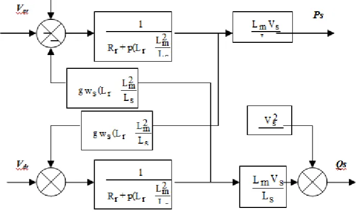
Equations (13) (14) (15) allow us to establish the block diagram of the MADA to regulate:
Fig.V.1 MADA block diagram regulate
IV.
synthesis of controllers
A. synthesizing a controller PI:He figure (3) show a closed loop system corrected by a PI controller
Fig. (3). PI controlled by a system
He transfer function of the open loop incorporating presence of regulators is:
G(p)=
) Ls L2m -Lr ( Ls
R r Ls + p
) Ls L2m -Lr ( R r Ls
Vs Lm
K p p
K p Ki + p
) Ls L2m -Lr ( Ls
R r Ls = K p
Ki
If the compensation is performed, one obtains the transfer function in open loop as follows:
G(p) = p
) Ls L2m -Lr ( Ls
Vs Lm K p
Which give us close loop:
H(p) = p τr + 1
1
whith:
Vs Lm
) Ls L2m -Lr ( Ls
K p 1 = τr
: he response time of the system that we set the order of 10ms.
We can now express sheaths correction based on the settings of the machines and the response time
Vs Lm
) Ls L2m -Lr ( Ls
τr 1 = K p
Vs Lm
R r Ls τr
1 = Ki
V.
Fuzzy control of active and reactive power of the DFIG
As we said in the previous paragraph we keep direct control by replacing regulators Proportional-Integral (PI) by more robust fuzzy controllers in the loop of power.
nference rules for determining the behavior of the fuzzy controller should thus include intermediate steps that allow him to pass real variables to the fuzzy variables and vice versa; these are the steps of fuzzification and defuzzification (see Figure .4).
Tab. Matrix inference of fuzzy controller.
Fig.4. llustration of internal steps of fuzzy regulation. ui
ei(w)
PB PM PS ZE NS NM NB
e(w)
NB ZE NS NM NB NB NB NB
NM PS ZE NS NM NB NB NB
NS PM PS ZE NS NM NB NB
ZE PB PM PS ZE NS NM NB
PS PB PB PM PS ZE NS NB
PM PB PB PB PM PS ZE NS
For membership functions, it has chosen for the three variable triangular shapes as shown in the following figure:
Fig.5. Entered and output membership functions of active power
He establishment of rules binding the outputs to the inputs, called the Fuzzy Inference.
VI.
Résultats des Simulation:
The simulation was done on the SIMULINK / MATLAB to perform the control environment tested. We therefore subjected the system to levels of active and reactive power in order to observe the behavior of its regulation.
fig.VII.1 Simulation results direct control
VII.
Conclusion:
In direct control, we conducted a synthesis of the PI controller and compare its performance in monitoring set, to variations of the parameters of the machine. The controller was the most effective for direct control, the model used to calculate the controller is simplified and even if the static accuracy is better, the transient performance of the controller are less.
To improve the strength of the direct control vis-a-vis the variations parameter of the machine, a blur synthesizing a controller is proposed. our apply a command to the active and reactive power it gives a good result. The major problem for controlling the power of the wind turbine asynchronous dual fuel and stator flux oriented is the determination of controller parameters, since this is usually done by trial and error.
Simulation results obtained show good performance and high robustness to parametric variations contrary to the results given by the PI controller. Parameters of wind system
Références
[1] A.Bendouga, "controle des puissance active et reactive de la machine asynchrone a double alimentation DFIM", thése doctorat, alger 2010
[2] D.Racoceanu et D. ould dbdeslam, "Résaux neuro-flous pour la surveillance des systèmes", 4éme conférence internationale sur l'automatisation industrielle monteral, canada, 2003
[3] R.metidji, F.achouri, "commande DPC de la DFIG dans un système de production d'énergie d'éolienne", 2rd international conférence : sciences of electronic; renewable energy and applications, April 15-16th,2012-algeria
[4] C. Belfedal, S.Moreau, G.Champenois, T.Allaoui, M.Denai, “Comparison of PI and Direct Power Control with SVM of Doubly Fed Induction Generator”, JOURNAL OF ELECTRICAL &
ELECTRONICS ENGINEERING, Vol. 8, No. 2, pp. 633-641, 2008.
[5] Lie X u, Senior, Phillip Cartwright, “Direct Active and Reactive Power Control of DFIG for Wind Energy Generation”, IEEE TRANSAC TIONS ON ENERGY CONVERSION, VOL. 21, NO. 3, pp.
750 – 758, 2006
[6] Jiabing Hu, ,HengNian, Bin Hu,YikangHe, Senior, Z. Q. Zhu , Fellow, “Direct Active and Reactive Power Regulation of DFIG Using Sliding-Mode Control Approach”, IEEE TRANSAC TIONS ON
ENERGY CONVERSION, Vol. 25, No. 4, pp. 1028 – 1039, 2010.
[7] GUO Xiao-Ming, Sun Dan, He Ben-Teng, Huang Ling-Ling, “Direct Power Control for Wind-Turbine Driven Doubly-Fed Induction Generator with Constant Switch Frequency”, Proceeding of International