Reactive Power Optimization Based on
Adaptive Immune Algorithm
Lin Jikeng Wang Xudong Zheng Weihong
Abstract – The adaptive immune algorithm (AIA)
developed from immune algorithm (IA), owns faster computation speed and better convergence than that of GA and other stochastic type algorithms, due to its characteristic of having two layers optimization. The adaptive immune algorithm automatically adjusts the parameters to achieve fast convergence without falling in the local minimum point, according to the value of the distance between the antibodies. It leads to great reduction of the computation time, compared withother methods. The paper proposes to apply adaptive immune algorithm for reactive power optimization. The coding method for the control variables based on decimal system is introduced in detail. The test results of example systems demonstrate that the proposed reactive power optimization based on AIA method has advantages in terms of computation speed and convergence, and has great potential to be applied in practical power systems.
Keyword-- Reactive Power Optimization, Adaptive Immune
Algorithm, Computation Speed, Coding method, decimal system
I. INTRODUCTION
HE purpose of reactive power optimization is to minimize the system loss or other optimum performance indices, subjecting to security and operation constraints. There are many solutions for it, such as linear programming, nonlinear programming, secondary programming, sensitive analysis, and mixed integer planning [1-4]. These methods are generally based on some presumptions and have some defects. With the development of artificial intelligent optimization technologies, the stochastic methods of global searching and optimization have attracted many interests, and have been applied in power system reactive power optimization.
In [5-7], methods based on GA,Tabu and fuzzy control, expert system, and neural network, are proposed with demonstration of good results.
1
The immune algorithm (IA), based on the mechanism of the amalgamation between antigen and antibody in biologic immune system, has been focused recently. IA has a faster computation speed and better convergence than that of GA and other stochastic type algorithms [8], due to its
1
Lin Jikeng (Ph.D)works as associated professor at the School of Electrical Power and Automation, Tianjin University, Tianjin, P. R. China. E-mail:[email protected].
Wang Xudong is a master degree candidate of Tianjin University, Tianjin, P. R. China
Zheng Weihong (B. D) works as a senior engineering at the Dispatch Center of Tianjin Electric Power Corporation, Tianjin, P.R.China
characteristic of having two layers optimization. IA has been applied to many fields in power system, such as optimal flow, distribution network planning, generator maintenance [9,10].
In this paper, AIA (Adaptive immune algorithm) [11] is applied to reactive power optimization of power system. The test results based on IEEE-14 system, IEEE-118 system and a practical system indicate that the reactive optimization based on the AIA presents remarkable performance in terms of computation speed and convergence rate, compared with those methods based on GA, IA.
II. AIA
The selection rate α, extension radius r, and mutation radius R are the key parameters for the IA and are fixed[10]. In optimization processing based on IA, the bigger α, r and R are , the higher the diversity of the colony is. However, the evolution of antibodies might be very slow. On the contrary, if the parameters are smaller, the algorithm can rapidly converge to local optimum, with the diversity of the colony significant decrease. Therefore, some inconsistency exists between the convergence rate and colony diversity for the IA.
If α, r and R are automatically adjusted according to the diversity of the antibodies, the algorithm might have fast convergence speed. If the diversity of the antibodies is defined as the average distance among antibodies, the smaller the distance is, the more similar the antibodies are, and the lower the colony diversity is, and vice versa. With
α, r and R being adjusted according to the diversity of the antibodies, the AIA gains good performance. Suppose that the antibody colony of thekth generation
B
kcontains m antibodies−v i
i,
=
1, 2,
L
,
m
, the average distance among these antibodies is calculated as:( )
(
)
1 1(
( ) ( ))
1
,
1
m m
k k k
i j i j
d
d v
v
m m
= ==
∑ ∑
−
,i
≠
j
(1)The diversity for antibody colony
B
k is defined as:( ) ( ) ( )
( )
max max
max 1
k k
k
k
d d d d
D
d d
⎧ <
⎪ = ⎨
≥
⎪⎩ (2)
Where
d
maxis constant.The parameter α, r and R of the kth generation are
automatically adjusted using the following equations:
( )k
D
( )kα
η
α
α
=
0+
(3)( )
(
( )k)
r k
D
r
r
=
0+
η
1
−
(4)( )
(
( )k)
Rk
R
D
R
=
0+
η
1
−
(5)where
α
( )k ,r
( )k , andR
( )k are selection rate, extension radius and mutation radius of the kth generation, respectively;α
0,r
0, andR
0 are the initial values of therelated parameters respectively;
η
α,η
r, andη
R are the adjusting ranges of the related parameters respectively. Then, the AIA process is as follows:(1) Initialization: Let k=0; randomly generate n real coding antibodies to form the initial antibody colony
A
k; calculate the evaluation of each antibody, which is the reciprocal of the objective function value.(2) Calculate
α
( )k ,r
( )k , andR
( )k with equations (1-4).(3) Selection operation: Select integer
(
n
∗
α
k)
=mantibodies whose evaluations are the m highest in colony
A
kto form antibody colonyB
k.(4) Extension operation: the neighborhood of each antibody in antibody colony
B
kis:( )
{
|
k,
,
k0,
}
i i i k
SN v
=
v v v
−
≤
r v
∈Ω
r
>
v
∈
B
,where
Ω
is the feasible solution space,•
isthe Euclidnorm,
r
k is extension radius; Each antibody in theantibody colony
B
k generates some new antibodiesrandomly in its neighborhood and all the new antibodies add tothe anitbody gy theomdomly and the totalationٛ ٛ ٛ ٛ ٛ ٛ ٛ ٛ ٛ ٛ ٛ ٛ ٛ ٛ ٛ ٛ ٛ ٛ ٛ ٛ ٛ ٛ ٛ ٛ ٛ ٛ ٛ ٛ ٛ ٛ ٛ ٛ ٛ ٛ ٛ ٛ ٛ ٛ ٛ ٛ ٛ ٛ ٛ ٛ ٛ ٛ ٛ ٛ ٛ ٛ ٛ ٛ ٛ ٛ ٛ ٛ ٛ ٛ ٛ ٛ ٛ ٛ ٛ ٛ ٛ ٛ ٛ ٛ ٛ ٛ ٛ ٛ ٛ ٛ ٛ ٛ ٛ ٛ ٛ the antibodies
in the
B
k to form the new antibody colony⎯C
k, in which the number of the antibodies isn
1. The roulette method is applied to determine the number of new antibodies generated by each antibody in colonyB
k.(5) Mutation operation: The
n
1 -integer(
n
1•
α
k)
antibodies whose evaluations are the
1
n
-integer(
n
1•
α
k)
worst in colonyC
kwill mutate into the antibodies in the larger area as following:( )
j{
|
j k,
,
k0
}
MN v
=
v v v
−
≤
R v
∈Ω
R
>
, andk k
R
>>
r
, the mutated antibodies and the rest in colonyC
kform the antibody colonyD
k.(6) Replacement operation: the L antibodies whose evaluations are the L worst in colony
D
kare replaced by the antibodies generated randomly to make up the antibody colonyE
k.(7) Retaining operation: the L antibodies whose evaluations
belong to the L worst in colony
E
kare replaced by Lantibodies whose evaluations belong to the L best in
colony
A
k to form the next generationA
k+1. If theconvergence criterion is satisfied, the procedure is over; otherwise, let k=k+1, return to step (2) 。
The evolutionary procedure of colony by AIA is shown as fig. 1:
Fig.1: The procedure of the evolution for the AIA
It can be seen that in the above algorithm, the
α
( )k ,r
( )kand
R
( )k are adjusted according to the distance among the antibodies in the current colony, and the compromise between the rapid convergence and high diversity of colony is achieved, so that it can prevent converging to local optimum and can have great improvement on computation speed.III. THE MATHEMATIC MODEL FOR REACTIVE POWER OPTIMIZATION
The mathematic model for reactive power optimization is as follows:
(1) Objective function
The objective function of reactive power optimization is:
, ,
( , , , , )
2
2 lim
lim
, ,
,max ,min , ,max , ,min
,max ,max lim
,min ,min , ,max , , ,max lim
,
, ,min , , ,min
( ) ( )
K T C i C i PV
L T K N Q i N V i N
G i G i i i
u Q
i i G i G i
i i i
i
i i i
G i G i G i G i
G i G i G i
Min F P
Q Q
V V
V V Q Q
in which
V V V
V
V V V
Q Q Q
Q
Q Q Q
λ
λ
∈ ∈ ∈ = +
−
− +
∑ ∑
− −
≥ ⎧⎪
= ⎨ ≤
⎪⎩
≥ ⎧⎪
= ⎨ ≤
⎪⎩
(6)
where
P
L is the branch-loss;V
i ,V
i,min , and,max
i
V
are the voltage of PQ bus, and its lower limit andupper limit, respectively;
Q
G,i,Q
G,i,min, andQ
G,i,maxand the upper limit, respectively;
T
K(
K
∈
N
T)
is the tap position of transformer, andN
T is the total number oftransformers;
Q
C i,(
i
∈
N
C)
is the compensationcapacity of capacitor (or reactor), and
N
C is the total number of capacitors (or reactors);V i
i(
∈
N
PV)
is thegenerator terminal voltage of PV bus, and
N
PV is thetotal number of PV buses.
In equation (6), the second and third parts are penalties on voltage and generator reactive power output limit
violation respectively, and
λ
u ,λ
Q are the penaltycoefficients.
(2) The constraint conditions
{
}
1 1 min max min max min max min max(
)
(7)
(
) (8)
1, 2,
,
(9)
(10)
(11)
(12)
i i i ii i i
i i i
j n
G D i j ij ij ij ij j
j n
G D i j ij ij ij ij j
G G G PV
i i i
k k k T
C C C C
P
P
VV G Cos
B Sin
Q
Q
VV G Sin
B Cos
i
n
Q
Q
Q
i
N
V
V
V
i
n
T
T
T
k
N
Q
Q
Q
i
N
θ
θ
θ
θ
= = = ==
+
∑
+
=
+
∑
−
∈
≤
≤
∈
≤ ≤
∈
≤ ≤
∈
≤
≤
∈
L
where, i GP
and i GQ
are the input real power and reactivepower at ith bus, respectively;
i
D
P
andi
D
Q
are the loads ofreal power and reactive power at ith bus, respectively;
n
is the total buses number; The voltages of PV buses, the compensated amounts of compensators (or reactors), and the tap positions of transformers are the control variables. The rest variables in equations (6)-(12) are state variables.
IV. THE REACTIVE POWER OPTIMIZATION BASED ON AIA
Since the control variables of reactive power optimization are the mixture of continuous variables and discrete variables, an efficient coding method for them must be designed, which will speedup the immune evolutionary procedure. The decimal coding method is applied for it.
A. The Coding Method
The configuration of antibody is given by
X
=
[
V
G|
Q
C|
T
]
(13)where,
{
}
1
,
,
NG G G
V
=
V
⋅⋅⋅⋅⋅⋅
V
,{
}
1
,
,
MC C C
Q
=
Q
⋅⋅⋅⋅⋅⋅
Q
,{
1,,
S}
T
=
T
⋅⋅⋅⋅⋅⋅
T
;X
is the coding of antibody;V
G ,C
Q
andT
are the terminal voltage vector of generators, the vector of reactive compensations, and the tap position vector of transformers, respectively;i
G
V
,i
C
Q
andT
iare components of relevant control vectors. The coding method for each control variable is as follows.
(1). Generator terminal voltage
Assume the number of PV generators is N. The adjustable range of ith generator terminal voltage, which is expressed as
V
Gimin≤
V
Gi≤
V
Gimax usually having limits between 1.1 and 0.9, is divided intow
units (i.e.w
=200, each unit is about 0.001, which definitely satisfies theprecision requirement.). Variable
,
i k
GV
(1
≤ ≤
i
N
,1
≤ ≤
k
w
, i, k is an integer), thegeneration terminal voltage of PV buses, is expressed as
max min min
,
Gi Gi i k Gi
V
V
GV
V
k
w
−
=
+
×
, which relates thevoltage value of all generators with the integer k. Then the coding value of
i
G
V
in equation (13) could be obtained asi
G
V
=
k
, and the relevant voltage could be obtained bydecoding through the formula
V
Gi=
GV
i k, . (2). Compensation capacity of compensatorSuppose that the number of buses with adjustable compensator is M, the group number of the ith compensation device is N, and the compensation capacity
of each group is
Q
c . The variable,
i t
CB
(1
≤ ≤
i
M
,1
≤ ≤
t
N
, i and t are integer) , whichis the compensation value of the ith reactive compensation devices having t group capacity banks being put on, is expressed as
CB
i t,=
CB
i t, 1−+
Q
c. Then the coding valuei
c
Q
in equation (13) is obtained asi
c
Q
=
t
, and therelevant compensation capacity could be obtained by
decoding through the equation ,
i
c i t
Q
=
CB
(3). The tap position of transformer.
Suppose that the number of transformers is S, and the position number for the tap of the ith transformer is L, and the difference between two successive transformer tap
positions (tap step) is
Δ
k
. The variable,
(1
,1
)
i j
TB
≤ ≤
i
S
≤ ≤
j
L
, which is the ratio of the tapposition of transformers, is expressed as
, , 1
i j i j
TB
=
TB
−+ Δ
k
. Then the coding value ofT
i inequation (13) is obtained as
T
i=
j
. The ratio of the ith transformer could be obtained by decoding through the formulaT
i=
TB
i j, .B. The Procedure For The Reactive Power Optimization Based On AIA
The procedure for the reactive power optimization based on AIA is as follows:
(1) Let the initial values of selection rate α, extension radius r and mutation radius R be:
α
0,r
0 andR
0to constitute antibody colony
A
k, k=0.(2) Perform the power flow calculation for each of the relevant decoding values of the antibody in colony
A
k, and discard the antibody whose decoding value could not satisfy the power flow equation; then calculate the value of objective function by equation (6), and achieve the evaluation for each antibody preserved.(3) Calculate
α
( )k ,r
( )k andR
( )k using equations (1-4).(4) Do the Selection operation, Extension operation, Mutation operation and Replacement operation just like that introduced at part 2 of this paper one after the other; if the convergence criterion is met, then the procedure ends; otherwise k=k+1, return to (2) to start the next generation evolution.
V. SIMULATION EXAMPLES
The reactive power optimization based on AIA is applied to the IEEE14, IEEE118 system and a practical system, and the results are compared with those obtained based on GA, IA. The initial parameters for the above method are nearly similar.
[image:4.612.319.539.44.278.2]For IEEE14 system, the colony scale is 100, and the optimization results are shown in table 1, where branch-loss and computation time are the average value of results of many time calculations. The fitting value curves are presented at figure 2.
TABLE 1:THE OPTIMIZATION RESULTS FOR THE IEEE14 SYSTEM
Algorithms Optimized
branch-loss(MW)
Iterative times
Calculation time
GA 13.502 30 58s
IA 13.390 30 61s
[image:4.612.74.293.390.607.2]AIA 12.308 30 3.5s
Fig.2: The curve of the fitting value for IEEE14 system
For the IEEE118 system, the colony scale is 150, and the optimization results are shown in table 2, and the curves of fitting value are shown in figure 2.
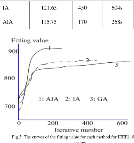
TABLE 2:THE OPTIMIZATION RESULTS FOR IEEE118 SYSTEM
Algorith ms
Optimized branch-loss(M W)
Iterative times
Calculatio n time
GA 122.10 560 761s
IA 121.65 450 604s
AIA 115.75 170 268s
Fig.3: The curves of the fitting value for each method for IEEE118 system
It could be seen clearly that from the table 1-2, the reactive power optimization method based on AIA proposed has superiority in the aspects of the computation speed and precision, compared to the other methods. The superiority is more obvious with the system scale enlarging. Fig. 2 and 3 also clearly indicate that the fitting value of AIA quickly surpasses those of other two methods and lead to more reasonable evaluation, since the bigger the fitting value, the more reasonable the system evaluation.
The reactive power optimization method based on AIA is also tested on a practical system in China. The system is composed of: 226 buses, 293 branches, 20 voltage adjustable generators, 77 tap adjustable transformers, and 46 capacitors. The total load of system is
3 6 0 .1 3
P l = M W , Q l = 4 3 .3 3M W . The simulation result is shown in table 3:
TABLE3:THE RESULTS FOR APRACTICAL SYSTEM
State loss(MW) Average
voltage
Violation buses
Before 22.395 0.942 147
After 20.394 1.047 0
It could be seen that from the Tab.3, that the method of reactive power optimization based on AIA proposed is very effective even for a practice system.
VI. CONCLUSION
In this paper, the AIA is proposed for reactive power optimization. AIA automatically adjusts all parameters such as selecting rate α, cloning radius r and mutation radius R, according to the distance measure between antibody and antibody, and lead to greatly reduce computation time. The AIA based reactive power optimization has remarkable superiority in computation speed and convergence speed, compared to those methods based on GA and IA. It has great potential for practical implementations.
[image:4.612.76.293.680.740.2]VII. REFERENCES
[1] Bjelogrlic M, Calovic M S, Ristanovic P, et al. Application of Newton’s optimal power flow in voltage/reactive power control [J]. IEEE Trans on power system, 1990, 5(4): 1447-1454.
[2] Ramirez-Arredondo J. M, Barocio E. E, Chacon O. L. The affine-scaling dual algorithm as an alternative to solve the power system state estimation problem [J]. IEEE Power Engineering Review, 1999, 19(6): 50-52
[3] M.J. Rider, V.L. Paucar, A.V. Grcia. Enhanced higher-order interior-point method to minimize active power losses in electric energy system[J]. IEE Proc.-Gener. Transm. Distrib., 2004, 151(4): 517-525
[4] DAS D B, PATVARDHAN C. “Reactive Power Dispatch with a Hybrid Stochastic Search Techniques”, Electric Power Energy System, 2002, 24(9): 731-736
[5] Shonkwiler, R., Mendivil, F. and Deliu, A. “Genetic Algorithms for the I-D Fractal Inverse Problem”. Proceedings of the 4th International Conference on Genetic Algorithms and Their Applications, pp: 495-501. University of California, San Diego, 1991
[6] Chen Y L, Liu C C, “Interactive Fuzzy satisfying method for optimal multi-objective VAR planning in power systems”, IEE
Proceedings-C 1994, 141(6): 554-560
[7] Venkatesh, B.; Sasadivam, G.; Abdullah Khan [M]. “Towards on-line optimal reactive power scheduling using ANN memory model based method”, Power Engineering Society 1999 Winter Meeting, IEEE, Volume 2, 31 Jan-4 Feb 1999 Page(s):844 - 848 vol.2
[8] J Timmis. Artificial Immune Systems: A Novel Data Analysis Technique Inspired By the Immune Network Theory, [D]. Department of Computer Science, University of Wales, Aberystwyth, Ceredigion, Wales, 2000-08
[9] Huang Shyh-Jier, “An immune-based optimization method to capacitor placement in a radial distribution system [J]”. IEEE Transaction on Power Delivery, 2000, 15(2): 744-749
[10] Lin C H, Chen C S, Wu C J, “Application of immune algorithm to optimal switching operation for distribution-loss minimisation and loading balance [J]”. IEE Proceedings of Generation, Transmission and Distribution, 2003, 150(2): 183-189