Http://www.ijetmr.com©International Journal of Engineering Technologies and Management Research [188]
E SHAPE MICROSTRIP PATCH ANTENNA WITH RECTANGULAR
AND CIRCULAR SLOT
Priyanka Jain 1, Dr. Raghavendra sharma 2, Dr. Vandana Vikas Thakre 3
1
Department of ECE, Amity School of Engineering and Technology, Amity University Madhya-Pradesh, Gwalior, M.P., India
2
HOD, Department of ECE, Amity School of Engineering and Technology, Amity University Madhya-Pradesh, Gwalior, M.P., India
3
Department of ECE, Madhav Institute of Technology and Science, Gwalior, M.P., India
Abstract:
In this proposed design a Rectangular E shaped micro-strip patch antenna is present with rectangular and circular slot within the Rectangular patch which operate at frequency 2.4 GHz. By proposed antenna design and coaxial feeding at suitable place the resultant return loss, VSWR and bandwidth will be find out. For the propose microstrip antenna we have use FR-4 substrate which contain permittivity of 4.4 and thickness 1.5, loss tangent is 0.02. HFSS simulation software is used for designing and analysis.
Keywords: Microstrip Patch Antenna; L-Shape; Multi-Band; Bandwidth; HFSS.
Cite This Article: Priyanka Jain, Dr. Raghavendra sharma, and Dr. Vandana Vikas Thakre. (2018). “E SHAPE MICROSTRIP PATCH ANTENNA WITH RECTANGULAR AND CIRCULAR SLOT.” International Journal of Engineering Technologies and Management Research, 5(2:SE), 188-193. DOI: https://doi.org/10.29121/ijetmr.v5.i2.2018.643.
1. Introduction
In recent instance the requirement for the multi-mode antenna is demanded for person to person communication network which have been rising. The growing amount of mobile services incorporated into particular telecommunication system which has made multiband function an important characteristic of mobile phone antennas [1]. In current years, the dual-band or multi-band antennas contain a huge awareness for application towards multimode communication systems [2]. It is finely known that standard of microstrip patch antennas are smart explanation of lot of wireless communication which demand due to their low-priced, average, comfortable, and easy-to-manufacture structural design [3]. On the other hand, the bandwidth of the main configuration in a lot of application is not enough to wrap up the needed functioning frequency range.
Http://www.ijetmr.com©International Journal of Engineering Technologies and Management Research [189]
such as slot, stub or shorting pin, it gives tuneable or multi frequency antenna features. For the most part a well-liked method for obtain multi-frequency behaviour is to introduce the slots lying on a single patch [5].
In this paper, a multiband E-shape microstrip patch antenna is proposed. The modified E-shape microstrip patch antenna shows the ability to create good result at required frequency band. The behaviour of the modified E-shape microstrip patch antenna is described in terms of return loss. The radiation patterns of the measured E shape microstrip patch antenna clearly show the power radiated by an antenna at required frequencies [6].
The proposed design presents an approach of the rectangular patch with E-type slot ofa rectangular and three circular slot in it, based with the commercial electromagnetic simulation tool, the FEM based software, HFSS by ANSOFT. Section II describes the antenna design and analysis for microstrip patch antenna. Simulations and results of antenna are projected in Section III. Conclusion is followed by the Section IV.
2. Antenna Design and Analysis
The proposed antenna construction is given away in Fig. 1. The rectangular microstrip patch of measurement W × L in print on the grounded substrate, which contain a relative permittivity εr
and also consistent by width h, the dielectric material is theoretically nonmagnetic by means of permeability μ0. The E-shaped slot with one rectangular three circular slots among measurement
(L2, W2), R is preset in a rectangular patch (see Figure 1), and the E-shaped patch rectangular antenna characteristics multi-band behaviour. The patch is feed with coaxial probe (50Ω) which is easy to formulate and have simulated radiation. In proposed feeding method, the coaxial connector with the inside conductor extend as of ground from end to end the substrate and is soldered to the radiating patch, whereas the external conductor extend from ground up towards substrate.
The propose mathematical design of the practical antenna is given below
Effective Dielectric Constant
(1)
Fringes Factor
( )( )
( )( )
(2)
Calculation of Length
L (3)
Http://www.ijetmr.com©International Journal of Engineering Technologies and Management Research [190]
√ (4)
Calculation of Width
√
(5)
Calculation of Ground Plane Dimensions
, (6)
Where W is width of patch and h is the height of substrate, L is length of patch ΔL is extension in length due to fringing effect and c is speed of light in free space ƒr is resonant frequency [5].
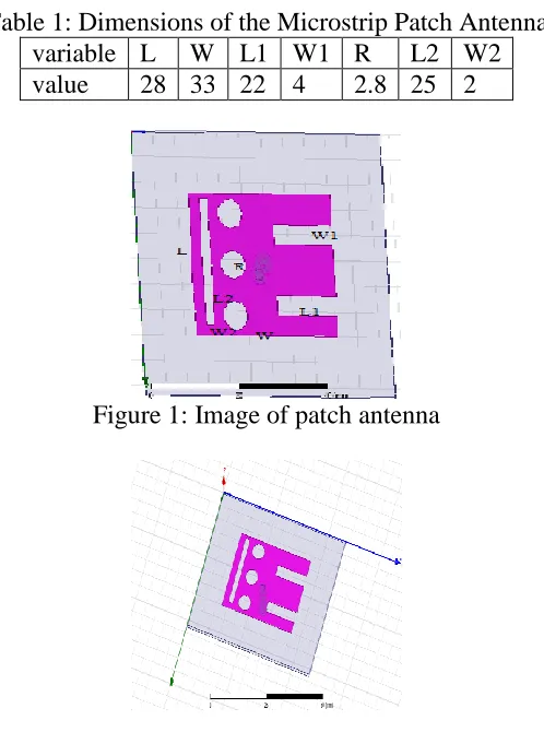
In this proposed design the computation of length and width are done by given formulas. The dimension of antenna is given by table 1. As shown in the figure.1 the patch has three types of L shaped slot their dimensions are also given in table1. We used „FR4‟ material for substrate which has dielectric constant 4.4 and height for this material is 1.5. Figure.2 shows the design of antenna in software.
Table 1: Dimensions of the Microstrip Patch Antenna variable L W L1 W1 R L2 W2 value 28 33 22 4 2.8 25 2
Figure 1: Image of patch antenna
Http://www.ijetmr.com©International Journal of Engineering Technologies and Management Research [191]
3. Simulation and Result Analysis
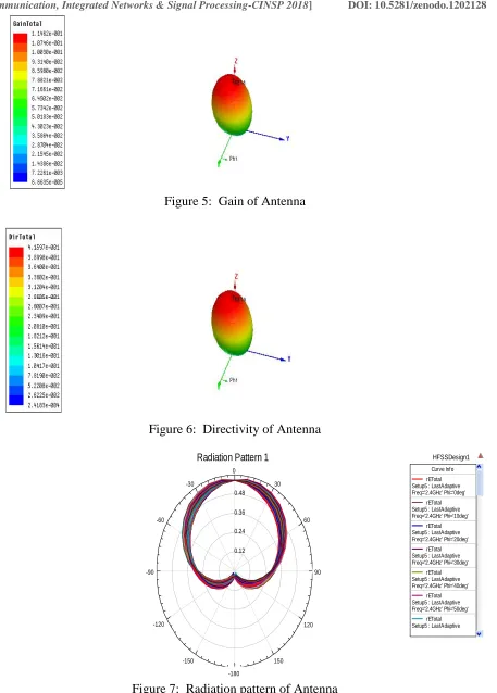
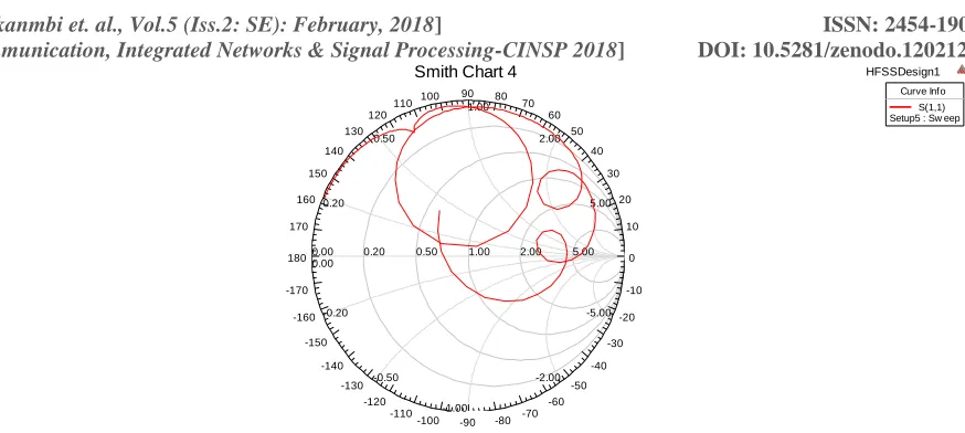
HFSS simulation software is use for the simulation of micro-strip patch antenna. The deviation of return loss with frequency is shown in figure (3) of rectangular patch antenna through this E shaped slot. The proportion ratio of the Fourier transform of the incident pulse and the reflected signal is defined as the return loss which is an essential factor for antenna design. Figure (4) shows the VSWR graph for E shaped slotted rectangular patch antenna which is below than 2 for this antenna. The VSWR indicate the difference among the transmission line and the antenna and for perfect matching the VSWR value must be close to unity. The return loss for the microstrip patch antenna is shown in the figure (3) by which the single band is getting by this proposed design is (2.84,-21.35). The bandwidth is calculate at the frequency range where the return loss is just about below the -10dB and by the calculation it is given as 211MHz. Gain and directivity of antenna is shown in figure5 and 6 the value of these are 9.55 and 3.60. Figure (7) shows the simulated radiation pattern in 3D and the Smith chart is shown in figure (8) for the E shaped Slotted rectangular micro-strip patch antenna.
Figure 3: Return Loss of Antenna
Figure 4: VSWR of Antenna
1.00 1.50 2.00 2.50 3.00 3.50 4.00 4.50 5.00
Freq [GHz] -22.50
-20.00 -17.50 -15.00 -12.50 -10.00 -7.50 -5.00 -2.50 0.00
d
B(S
(1
,1
))
HFSSDesign1 XY Plot 100
Curve Info dB(S(1,1)) Setup5 : Sw eep
1.00 1.50 2.00 2.50 3.00 3.50 4.00 4.50 5.00 Freq [GHz]
0.00 25.00 50.00 75.00 100.00 125.00 150.00 175.00 200.00 225.00
VS
W
R
(1
)
HFSSDesign1 XY Plot 101
m1
Curve Info VSWR(1) Setup5 : Sw eep Name X Y
Http://www.ijetmr.com©International Journal of Engineering Technologies and Management Research [192]
Figure 5: Gain of Antenna
Figure 6: Directivity of Antenna
Figure 7: Radiation pattern of Antenna
0.12 0.24 0.36 0.48
90 60 30 0
-30
-60
-90
-120
-150
-180
150 120
HFSSDesign1 Radiation Pattern 1
Curve Info
rETotal Setup5 : LastAdaptive Freq='2.4GHz' Phi='0deg'
rETotal Setup5 : LastAdaptive Freq='2.4GHz' Phi='10deg'
rETotal Setup5 : LastAdaptive Freq='2.4GHz' Phi='20deg'
rETotal Setup5 : LastAdaptive Freq='2.4GHz' Phi='30deg'
rETotal Setup5 : LastAdaptive Freq='2.4GHz' Phi='40deg'
rETotal Setup5 : LastAdaptive Freq='2.4GHz' Phi='50deg'
Http://www.ijetmr.com©International Journal of Engineering Technologies and Management Research [193]
Figure 8: Smith chart representation of Antenna
4. Conclusion
The proposed E-shaped slot loaded rectangular microstrip patch structure can operate on more than two resonance frequencies and consequently this design can be used for multi band Operation. The properties of different physical parameter of antenna are investigated on the characteristics of this configuration. The present configuration could be capable of to meet up the requirement of different frequencies of wireless communication systems directly besides introducing slots of E-type in the dimension of the main antenna. Mathematical result show that in cooperation with the upper and lower resonant frequencies, the band widths relate to the dimension of the slot, by appropriately choosing the position of feed point and the slots multi bands can be achieved and controlled.
References
[1] Kisangiri Michael, Andrzej A. Kucharski, “GENETIC ALGORITHM OPTIMIZATION FOR MULTIBAND PATCH ANTENNA DESIGN”, Proc. „EuCAP 2006‟, Nice, France 6–10 November 2006 (ESA SP-626, October 2006)
[2] Amel Boufrioua, “Dual Band Semi Circular Disk Patch Antenna Loaded With L-Shaped Slot”, SAI, CDKP, ICAITA, NeCoM, SEAS, CMCA, ASUC, Signal – 2014 pp. 189–195, 2014.
[3] Yejun He, Jiefeng Ao, Xiaorong Tang and Jie Yang, “The Optimum Design of PIFA Based on HFSS and Genetic Algorithm”, 978-1-4244-6252-0/11/$26.00 ©2011 IEEE
[4] Yong-Xin Guo, Kwai-Man Luk, Kai-Fong Lee, "A Quarter-Wave U-Shaped Patch Antenna With Two Unequal Arms for Wideband and Dual-Frequency Operation", IEEE Trans. on AP, vol. 50, No.8, pp. 1082-1087, August 2002
[5] J. Malik and M. V. Kartikeyan, “Metamaterial Inspired Patch Antenna With L-Shape Slot Loaded Ground Plane For Dual Band (Wimax/Wlan) Applications”, Progress In Electromagnetics Research Letters, Vol. 31, 35-43, 2012
[6] Lavi Agarwal, Prateek Rastogi, “Multiband L Shape Microstrip Patch Antenna for Wireless Communication”, MIT International Journal of Electronics and Communication Engineering, Vol. 3, No. 2, August 2013, pp. 104–107
5.00 2.00 1.00 0.50 0.20 0.00 5.00 -5.00 2.00 -2.00 1.00 -1.00 0.50 -0.50 0.20 -0.20 0.00 0 10 20 30 40 50 60 70 80 90 100 110 120 130 140 150 160 170 180 -170 -160 -150 -140 -130 -120 -110
-100 -90 -80 -70 -60 -50 -40 -30 -20 -10 Curve Info S(1,1) Setup5 : Sw eep
*Corresponding author.
![Figure 3: Return Loss of Antenna Freq [GHz]](https://thumb-us.123doks.com/thumbv2/123dok_us/8977536.1886904/4.612.123.472.296.729/figure-return-loss-antenna-freq-ghz.webp)