*Corresponding author:Rajiv Banerjee ISSN: 0976-3031
Research Article
ANALYTICAL STUDY ON THE STRUCTURE BEHAVIOUR OF REGULAR AND
IRREGULAR SPACE FRAME BY STAAD.PRO V8i
Kuldeep Kumar Chaudhary., Sabih Ahmad., Syed Aqeel Ahmad.,
Anwar Ahmad and Rajiv Banerjee*
Department of Civil Engineering Integral University, Lucknow, India
DOI: http://dx.doi.org/10.24327/ijrsr.2018.0905.2115
ARTICLE INFO ABSTRACT
The behaviour of G+9 space frame building of regular and irregular configuration under earthquake is complex and to act as simultaneously with earthquake loads. In this paper an industrial G+9 space frame building is studied for earthquake using STAAD-PRO V8I. The behaviour of building ability to dissipate energy and effect of the lateral deformation. This paper is concerned with the effects of two type irregularities on this seismic response of a structure. Lower stiffness results in higher displacements of upper stories. Tall structures were found to have lower natural frequency hence their response was found to be maximum in a lower frequency earthquake. It is because low natural frequency of tall structures subjected to low frequency earthquake leads to resonance resulting in large displacements earthquake engineering is to design and build a structure in such a way that the damage to the structure and its structural component during an earthquake is minimized. The component of the building, which resists the seismic force, is known as lateral force resisting system. The damage in a structure generally initiates at location of the structural weak planes present in the building system. The weaknesses obtained occur due to presence of the structural irregularities in stiffness, strength and mass in a building system. The structural irregularity can be broadly classified as plan and vertical irregularities. The maximum deflection produced in the structure, weight of steel required by the structure and percentage of failed member has been considered as measured. Optimization is a process of subjecting all members present in the structure to minimum usage thereby ensuring the utilization ratio of each and every element more than 80%. It is to be noted that the structural properties not be compromised.
INTRODUCTION
Many buildings in the present scenario have irregular configuration both in plan and elevation which in future may subject to devastating earthquakes. In case, it is necessary to identify the performance of the structures to withstand against disaster primarily due to earthquake. However, the behaviour of the structures with these irregularities is not avoidable in construction of buildings. However, the behaviour of structures with these irregularities during earthquakes needs to be studied. Adequate precautions can be taken. A detailed study of structural behaviour of the building with irregularities is essential for design and behaviour in earthquake. Several related studies have focused on evaluating the response of regular structures. However, there is a lack of understanding of the seismic response of the structure with irregularities. During an earthquake failure of structure starts at point of weakness. This weakness arises due to discontinuity in mass, stiffness,
and geometry of structure. The structure having this discontinuity is termed as irregular structures. The difference in usage of a specific floor with respect to the adjacent floors results in irregular distributions of mass, stiffness, and strength along the building height.
The growing interest in space frame structure has a witnessed worldwide over a last half century. It forms to accommodate large unobstructed area and satisfy the requirement for lightness economy and speedy construction. New and imaginative application of space frame are being demonstrated in the total range of building types such as sport arenas, exhibition pavilions assembly halls transportation terminals, airplane hangars, workshops warehouse. They have been used not only on long span roofs but also on mid and short span enclosure as roofs, floors exterior wall and canopies. But the space frame highly statically in determined and their analysis lead to extremely tedious computation if done by hand. The
International Journal of
Recent Scientific
Research
International Journal of Recent Scientific Research
Vol. 9, Issue, 5(D), pp. 26749-26754, May, 2018
Copyright © Kuldeep Kumar Chaudhary et al, 2018, this is an open-access article distributed under the terms of the Creative Commons Attribution License, which permits unrestricted use, distribution and reproduction in any medium, provided the original work is properly cited.
DOI: 10.24327/IJRSR
CODEN: IJRSFP (USA)
Article History:
Received 17th February, 2018
Received in revised form 12th
March, 2018
Accepted 04th April, 2018
Published online 28th May, 2018
Key Words:
difficulty of complicated analysis as such system has contributed his limited use. A space frame or space structure is a truss like, lightweight rigid structure constructed from interlocking struts in a geometric pattern. Space frame can be used to span large areas with few interior supports. In practice the rigid jointed frames such as building frames are usually three-dimensional space structure.
METHDOLOGY
(G+9) Industrial building (both RCC & Steel) is analysed & design on STAAD- PRO Software by considering following loads. Earthquake & wind analysis is done for Delhi Region (zone -IV) for both steel as well as RCC building. Keeping the loading conditions, span of beams same applying Indian code provisions for (G+ 9) industrial buildings. It is observed that, by using ISMB sections as columns.
Analysis of space frame
Seismic Analysis
Seismic analysis is a major tool in earthquake engineering which is used to understand the response of buildings are in seismic excitations in a simpler manner. In the past the buildings were designed just for gravity loads and seismic analysis is a recent development. It is a part of structural analysis and a part of structural design where earthquake is prevalent.
1. Equivalent Static Analysis 2. Response Spectrum Analysis 3. Time History Method
Equivalent Static Analysis: -The equivalent static analysis
procedure is essentially an elastic design technique. It is however simple to apply than the multi-model response method, with the absolute simplifying assumption being arguably more consistent with other assumptions absolute elsewhere in the design procedure.
a. Estimate the first mode response period of the building from the design response spectra.
b. Use the specific design spectre to determine that the lateral base shear of the complete building is consistent with the level of the post-enatic response assumed.
Response Spectrum Analysis: -This approach permits the
multiple modes of response of a building to be taken into account. This is required in many building codes for all expect for very simple or very complex structures. The structural response can be defined as a combination of many modes. Computer analysis can be used to determine these modes for a structure. For each mode, a response is obtained from the design spectrum, corresponding to the model frequency and the modal mass, and then they are combined to estimate the total response of the structure. In this the magnitude of forces in all directions is calculated and then effects on the building are observed.
Time History Analysis: -Time history analysis techniques
involve the stepwise solution in the time domain of the multidegree-of- freedom equations of motion which represent the actual response of a building. It is the most sophisticated analysis method available to a structural engineer. Its solution is a direct function of the earthquake ground motion selected as
an input parameter for a specific building. This analysis technique is usually limited to checking the suitability of assumptions made during the design of important structures rather than a method of assigning lateral forces themselves.
Dead Loads: -All permanent constructions of the structure
form the dead loads. The dead load comprises of the weights of walls, partitions floor finishes, false ceilings, false floors and the other permanent constructions in the buildings. The dead load loads may be calculated from the dimensions of various members and their unit weights. the unit weights of plain concrete and reinforced concrete made with sand and gravel or crushed natural stone aggregate may be taken as 24 kN/m” and 25 kN/m” respectively.
Imposed Loads: - Imposed load is produced by the intended
use or occupancy of a building including the weight of movable partitions, distributed and concentrated loads, load due to impact and vibration and dust loads. Imposed loads do not include loads due to wind, seismic activity, snow, and loads imposed due to temperature changes to which the structure will be subjected to, creep and shrinkage of the structure, the differential settlements to which the structure may undergo.
Design Wind Speed (VZ): - The basic wind speed (VZ) for any
site shall be obtained from and shall be modified to include the following effects to get design wind velocity at any height (Vb) for the chosen structure.
Risk level
Terrain roughness, height and size of structure Topography
It can be mathematically expressed as follows: Where:
V = Vb* K1 *K2* K3
Vb = Design wind speed at any height z in m/s K1= Risk Coefficient
K2 = Terrain, height and structure size factor K3 = Topography factor
Risk Coefficient: -Risk Coefficient (K1 Factor) gives basic
wind speeds for terrain Category 2 as applicable at 10 m above ground level based on 50 years mean return period. In the design of all buildings and structures, a regional basic wind speed having a mean return period of 50 years shall be used.
Terrain,Height and Structure Size Factor: -Terrain Selection
of terrain categories shall be made with due regard to the effect of obstructions which constitute the ground surface roughness. The terrain category used in the design of a structure may vary depending on the direction of wind under consideration. Wherever sufficient meteorological information is available about the nature of wind direction, the orientation of any building or structure may be suitably planned.
Topography: -The basic wind speed Vb takes account of the
Problem layout
Design of G+9 storied by taking space frame and compares the results with regular and irregular space frame as well as steel variants including are as follows.
1. Soil parameters
2. Earthquake zone IV th and values of coefficient and acceleration spectra based on available local data. 3. Wind speed
4. Terrain category & topography
All steel has been designed assuming conformity to IS: 800 2007 satisfying durability requirements for Delhi. Further compare the following results are as follows
1. Displacement 2. Storey Drift 3. Base Shear 4. Mode Shape
Other design considerations (Both for RCC & Steel Frame)
Table I
No. Item
1. Grade of concrete used
M25 for slab and beams in RCC
variant only, M
concrete components in all variants
M25 for foundations in all variants
2. Grade for reinforcing steel
3. Grade of structural steel As per IS
4. Earthquake zone Zone-IV As per IS
5. Concrete cover to
reinforcement for slab
6. Concrete cover to
reinforcement for beams
7. reinforcement for columns Concrete cover to
8. Imposed load (Live load over
floor) 4.0 Kn/m
9. Roof Floor Live Load 1.5
Analysis of Regular Space Frame Plan
Fig 1 Regular space frame are (50m x30 m)
Design of G+9 storied by taking space frame and compares the results with regular and irregular space frame as well as steel
Earthquake zone IV th and values of coefficient and spectra based on available local data.
All steel has been designed assuming conformity to IS: 800- 2007 satisfying durability requirements for Delhi. Further
Other design considerations (Both for RCC & Steel- Space
Material
for slab and beams in RCC
variant only, M25 for all other
concrete components in all variants for foundations in all variants
Fe-415 As per IS-2062,250 MPa
IV As per IS-1893
20mm
25mm
40mm
4.0 Kn/m2
Kn/m2
Regular space frame are (50m x30 m)
Fig 2 RCC & Steel Regular Space Frame Model)
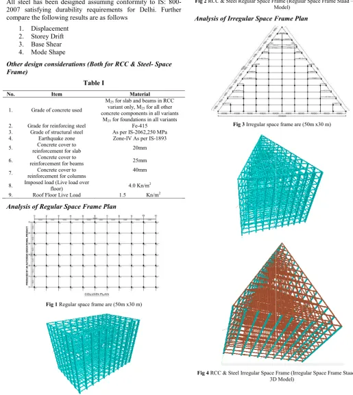
Analysis of Irregular Space Frame Plan
Fig 3 Irregular space frame are (50m x30 m)
Fig 4 RCC & Steel Irregular Space Frame (Irregular Space Frame Staad 3D Model)
RCC & Steel Regular Space Frame (Regular Space Frame Staad –Pro 3D Model)
Analysis of Irregular Space Frame Plan
Irregular space frame are (50m x30 m)
RESULTS
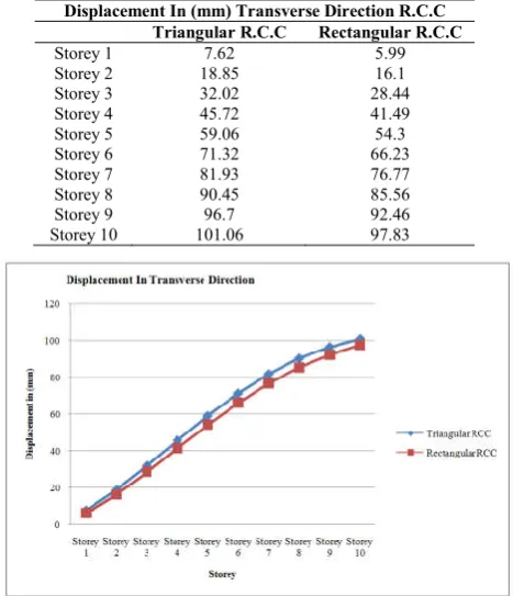
Displacement
The displacement of all models has been analysis. All displacement of all models is tabulated in form of graph for different stories for transverse direction.
Table I Regular and Irregular RCC Space Frame Displacement
Displacement In (mm) Transverse Direction R.C.C Triangular R.C.C Rectangular R.C.C
Storey 1 7.62 5.99
Storey 2 18.85 16.1
Storey 3 32.02 28.44
Storey 4 45.72 41.49
Storey 5 59.06 54.3
Storey 6 71.32 66.23
Storey 7 81.93 76.77
Storey 8 90.45 85.56
Storey 9 96.7 92.46
Storey 10 101.06 97.83
Fig 5 Plot for Displacement in (mm) Transverse Direction Rectangular and Triangular RCC
Table II Regular and Irregular Steel Space Frame Displacement
Displacement In (mm) Transverse Direction Steel Triangular Steel Rectangular Steel
Storey 1 3.22 3.09
Storey 2 8.09 8.28
Storey 3 14.04 14.66
Storey 4 20.44 21.63
Storey 5 26.84 28.74
Storey 6 32.87 35.63
Storey 7 38.23 41.95
Storey 8 42.69 47.43
Storey 9 46.15 51.83
Storey 10 48.8 55.3
Fig 6 Plot for Displacement in (mm) Transverse Direction Rectangular and Triangular Steel
Storey Drift
Storey drift can be defined as the lateral displacement of one level relative to the level above are below it: As per clause no. 7.11.1 of IS 1893 (Part-1): 2002, the storey drift in any storey due to specified design lateral force with partial load factor of 1.0, shall not exceed 0.004 times the storey height.
Table III Regular and Irregular RCC Space Frame Storey Drift
Storey Drift In (mm) Transverse Direction R.C.C Triangular R.C.C Rectangular R.C.C
Storey 1 6.941 5.650
Storey 2 11.235 10.174
Storey 3 13.165 12.339
Storey 4 13.709 12.60
Storey 5 14.80 13.10
Storey 6 16.30 13.90
Storey 7 18.10 14.20
Storey 8 18.89 15.38
Storey 9 19.67 16.98
Storey 10 20.2 18.36
Fig 7 Plot for Storey Drift in (mm) Transverse Direction Rectangular and Triangular RCC
Table IV Regular and Irregular Steel Space Frame Storey Drift
Storey Drift In (mm) Transverse Direction Steel Triangular steel Rectangular steel
Storey 1 2.9195 2.9356
Storey 2 4.883 5.1832
Storey 3 5.9477 6.3882
Storey 4 6.3991 6.9697
Storey 5 7.29 7.1109
Storey 6 8.40 7.96
Storey 7 10.20 8.20
Storey 8 11.96 11.29
Storey 9 12.75 12.1
Storey 10 13.98 12.30
Fig 8 Plot for Storey Drift in (mm) Transverse Direction Rectangular and Triangular Steel
0 10 20 30 40 50 60
Stor
ey
1
Stor
ey
2
Stor
ey
3
Stor
ey
4
Stor
ey
5
Stor
ey
6
Stor
ey
7
Stor
ey
8
Stor
ey
9
Stor
ey
10
Displace
men
t
In
(mm)
Storey
Displacement In Transverse Direction
Triangular Steel
Rectangular steel
0 5 10 15 20 25
St
o
re
y
Drif
t
In (m
m
)
Storey
Storey Drift In Transverse Direction
Triangular RCC
Rectangular RCC
0 2 4 6 8 10 12 14 16
St
o
rey
Drif
t
In
(m
m)
Storey
STOREY DRIFT IN TRANSVERSE DIRECTION
Triangular Steel
Base Shear
Base shear is the maximum expected lateral force that will occur due to seismic ground motion at the base of structure. Below figures compares the base shear values of the model’s directions respectively using linear static method.
Fig 9 Base Shear in rectangular RCC
Fig 10 Base shear in Triangular RCC
Fig 11 Base shear in rectangular Stee
Fig 12 Base shear in Triangular Steel Mode Shape
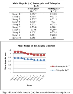
A mode shape is a specific pattern of vibration executed by a mechanical system at a specific frequency. Different mode shape will be associated with different frequenc
Base shear is the maximum expected lateral force that will at the base of structure. Below figures compares the base shear values of the model’s directions respectively using linear static method.
Base Shear in rectangular RCC
Base shear in Triangular RCC
Base shear in rectangular Steel
Base shear in Triangular Steel
A mode shape is a specific pattern of vibration executed by a mechanical system at a specific frequency. Different mode shape will be associated with different frequencies.
Table V Regular and Irregular RCC Space Frame Mode Shape
Mode Shape in (cm) Rectangular and Triangular Triangular
R.C.C
Storey 1 0.7627
Storey 2 0.7644
Storey 3 0.7597
Storey 4 0.7057
Storey 5 0.7058
Storey 6 0.7048
Storey 7 0.895
Storey 8 0.6582
Storey 9 0.6541
Storey 10 0.6581
Fig 13 Plot for Mode Shape in (cm) Transverse Direction Rectangular and Triangular RCC
Table VI Regular and Irregular Shape
Mode Shape in (cm) Rectangular and Triangular Steel Triangular Steel
Storey 1 0.9208
Storey 2 0.913
Storey 3 0.9
Storey 4 0.896
Storey 5 0.877
Storey 6 0.821
Storey 7 0.813
Storey 8 0.79
Storey 9 0.783
Storey 10 0.756
Fig 14 Plot for Mode Shape in (cm) Transverse Direction Rectangular and Triangular Steel
0 0.2 0.4 0.6 0.8 1 1.2
M
o
de S
h
ape
In
(cm)
Storey
Mode Shape In Transverse Direction
0 0.5 1 1.5 2
Stor
ey
1
Stor
ey
2
Stor
ey
3
Stor
ey
4
Stor
ey
5
Stor
ey
6
Stor
ey
7
Mode
Sh
a
pp
e
In(
cm
)
Storey
Displacement In Transverse Direction
Regular and Irregular RCC Space Frame Mode Shape
Mode Shape in (cm) Rectangular and Triangular RCC
Triangular R.C.C
Rectangular R.C.C
0.7627 0.3308
0.7644 0.3315
0.7597 0.3315
0.7057 0.33
0.7058 0.2788
0.7048 0.2801
0.895 0.2807
0.6582 0.2788
0.6541 0.2584
0.6581 0.258
Plot for Mode Shape in (cm) Transverse Direction Rectangular and Triangular RCC
Regular and Irregular Steel Space Frame Mode Shape
Mode Shape in (cm) Rectangular and Triangular Steel Triangular Steel Rectangular Steel
0.9208 0.901
0.913 0.89
0.9 0.876
0.896 0.864
0.877 0.859
0.821 0.846
0.813 0.823
0.79 0.819
0.783 0.79
0.756 0.788
Plot for Mode Shape in (cm) Transverse Direction Rectangular and Triangular Steel
Mode Shape In Transverse Direction
Rectangular RCC
Triangular RCC
Stor
ey
7
Stor
ey
8
Stor
ey
9
Stor
ey
1
0
Storey
Displacement In Transverse Direction
Rectangular steel
CONCLUSION
1. The plan configuration of structure has significant impact on the seismic impact on the seismic response of structure in terms of displacement, storey drift, storey shear.
2. According to results the storey shear (base shear) was found to be maximum for the top storey and it decreased to a maximum in the bottom storey in all cases.
3. Large displacement was observed in the triangular RCC building with severe irregularity shows maximum displacement and storey drift.
4. According to results of it was found that expressive larger base shear than regular building. And it is observed that the storey drift for all the stories are found to be within the permissible limits.
5. It is observed that the seismic forces are maximum on the regular structure because of higher plan area. Minimum displacement was observed in the Triangular steel building. It indicates that building with safe irregularity shows average displacement and storey drift. 6. In the study the different parameters such as soil structure interaction, soil types, zone types, natural frequency, natural period, base reaction, storey drift and lateral displacement are considered and these parameters important in the analysis of the RCC frame with irregular space frame structures.
7. As the number of storey increases in the building, the lateral displacement, natural frequency, base reaction and storey drift also increases.
8. The natural period decreases with the increases number of stores in the building for regular space frame comparison to irregular space frame.
9. The value of lateral displacement, storey drift and base reaction (base shear) of RCC frame with irregular building with soil continued is more compare to the irregular space fixed base and spring model.
References
1. C.K. Wang, Intermediate structures (McGraw Hills, 2004).
2. Aggarwal and Shrikhande, Earthquake resistant design of structures, (PHI Learning Limited, 2006).
3. Arvindreddy, R.J.Fernandes (2015),“Seismic analysis of RC regular and irregular frame structures”, International Research Journal of Engineering and Technology (IRJET), Volume: 02, Issue: 05
4. IS: 875(Part 2) – 1987 (Reaffirmed 2003), Code of Practice for Design Loads (Other than Earthquake) For Buildings and Structures (Second Revision).
5. IS: 456-2000 (Reaffirmed 2005), Indian Standard Code of Practice for Plain and Reinforced Concrete (Fourth Revision), Bureau of Indian Standards, New Delhi.
6. IS:1893-2002, Indian Standard Recommendations for Earthquake Resistant Design of Structures, Bureau of Indian Standards, New Delhi
7. Aakash Pathak, Rahul Satbhaiya (2016), “A Study of Seismic Strengthening of Multi Storey Building”, International Research Journal of Engineering and Technology (IRJET), Volume: 03 Issue: 05.
8. Naveed Anwar and Mohammad Qaasim (2016), “Parametric Study of Reinforced Concrete Column Cross Section for Strength and Ductility”, Academia, Vol 3.
9. Column”, International Journal of Science and Research (IJSR), 2319-7064.
10. Milind V and Mohod (2015), “Effect Of Shape And Plan Configuration On Seismic Response Of Structure”, International Journal Of Scientific & Technology Research Volume 4, Issue 09.
11. Shreyasvi .C B. Shivakumaraswamy (2015), “A Case Study on Seismic Response of Buildings with Re Entrant Corners”, International Journal of Engineering Research & Technology, Issn: 2278-0181,Vol. 4 Issue 05, May2015
12. Thanh Phuong Pham and Bing Li (2015), “Seismic Performance Assessment of L-Shaped Reinforced Concrete Columns”, ACI Structural Journal.
13. Ami A. Shah,B. A. Shah (2014), “Seismic Evaluation Of RC Space Frame With Rectangular and Equivalent Square Column By Pushover Analysis”, International Journal of Research in Engineering and Technology, pISSN: 23217308.
14. Pei-Shan Chen, “A Study Report on an Ancient Wood Bridge Hongqiao”, Structural Engineering International, 2008. 2, pp84-87.
15. Pei-Shan Chen, “Configuration and Structural Principle of an Ancient Chinese Wood Bridge Hongqiao”, Proceeding of IASS2007, 2007. Dec.
16. Pei-Shan Chen, “A study on the geometrical configuration of an ancient wooden bridge in Qingming Shanghe Tu”, Proceeding of IASS2010, Shanghai, 2010. Nov.
17. Pei-Shan Chen, “A Report on the Innovation of 1.5-Layer Space Frames”, Proceeding of IABSE IASS 2011, London, 2011.Sep.
18. Olga Popovic Larsen, “Reciprocal Frame Architecture”, Elsevier Ltd., 2088.
19. José Sánchez, Félix Escrig, “Frames Designed by Leonardo with Short Pieces An Analytical Approach”, International Journal of Space Structures, Volume 26, No. 4/December
*******
How to cite this article:
Kuldeep Kumar Chaudhary et al.2018, Analytical Study on the Structure Behaviour of Regular and Irregular Space Frame by Staad.Pro V8i. Int J Recent Sci Res. 9(5), pp. 26749-26754.