Available online: https://edupediapublications.org/journals/index.php/IJR/ P a g e | 515
Enumarating Heat Transfer Rate of Cylinder Fin Body by Varying
Geometry and Material
ARUKALA KRISHNA
Assistant professor, Dept. Mechanical engineering mother Theressa College of engg & tech. Peddapalli, , india
E-Mail: [email protected]
The Engine cylinder is one of the major automobile components, which is subjected to high temperature variations and thermal stresses. In order to cool the cylinder, fins are provided on the cylinder to increase the rate of heat transfer. By doing thermal analysis on the engine cylinder fins, it is helpful to know the heat dissipation inside the cylinder. The principle implemented in this project is to increase the heat dissipation rate by using the invisible working fluid, nothing but air. We know that, by increasing the surface area we can increase the heat dissipation rate, so designing such a large complex engine is very difficult. The main purpose of using these cooling fins is to cool the engine cylinder by air. The main aim of the project is to analyze the thermal properties by varying geometry, material and thickness of cylinder fins. Parametric models of cylinder with fins have been developed to predict the transient thermal behavior. The models are created by varying the geometry, rectangular, circular and curved fins. Present thickness of the fin is 3mm, it is reduced to 2.5mm. The 3D modeling software used is Pro/ Engineer. Presently Material used for manufacturing cylinder fin body is Aluminum Alloy 204 which has thermal conductivity of 110-150W/mk. In our project, it is replaced with Aluminum alloy 7075, Magnesium alloy and Beryllium and the total analysis is done in Ansys.
Keywords: Engine cylinder fins, Thermal analysis, Aluminum alloy 7075, Magnesium alloy, Beryllium
INTRODUCTION
The internal combustion engine is an engine in which the combustion of a fuel (normally a fossil fuel) occurs with an oxidizer (usually air) in a combustion chamber. In an internal combustion engine, the expansion of the high-temperature and -pressure gases produced by combustion applies direct force to some component of the engine, such as
pistons, turbine blades, or a nozzle. This force
moves the component over a distance, generating useful mechanical energy.
Necessity of Cooling System in IC Engines
All the heat produced by the combustion of fuel in the engine cylinders is not converted into useful power at the crankshaft. A typical distribution for the fuel energy is given below:
Available online: https://edupediapublications.org/journals/index.php/IJR/ P a g e | 516
Useful work at the crank shaft = 25 %
Loss to the cylinders walls = 30 %
Loss in exhaust gases = 35 %
Loss in friction = 10 %
It is seen that the quantity of heat given to the cylinder walls is considerable and if this heat is not removed from the cylinders it would result in the preignition of the charge. In addition, the lubricant would also burn away, thereby causing the seizing of the piston. Excess heating will also damage the cylinder material.
Keeping the above factors in view, it is observed that suitable means must be provided to dissipate the excess heat from the cylinder walls, so as to maintain the temperature below certain limits.
However, cooling beyond optimum limits is not desirable, because it decreases the overall efficiency due to the following reasons:
1. Thermal efficiency is decreased due to
more loss of heat to the cylinder walls.
2. The vaporization of fuel is less; this
results in fall of combustion efficiency.
3. Low temperatures increase the viscosity of
lubrication and hence more piston friction
is encountered, thus decreasing the
mechanical efficiency.
Though more cooling improves the
volumetric efficiency, yet the factors mentioned above result in the decrease of overall efficiency. Thus it may be observed that only sufficient cooling is desirable and any deviation from the optimum limits will result in the deterioration of the engine performance.
Methods of Cooling
Various methods used for cooling of automobile engines are:
1. Air cooling
2. Water cooling
Air-Cooling
Cars and trucks using direct air cooling (without an intermediate liquid) were built over a long period beginning with the advent of mass produced passenger cars and ending with a small and generally unrecognized technical change. Before World War II, water cooled cars and trucks routinely overheated while climbing mountain roads, creating geysers of boiling cooling water. This was considered normal, and at the time, most noted mountain roads had auto repair shops to minister to overheating engines.
ACS (Auto Club Suisse) maintains historical monuments to that era on the Susten Pass where two radiator refill stations remain (See a picture here). These have instructions on a cast metal plaque and a spherical bottom watering can hanging next to a water spigot. The spherical bottom was intended to keep it from being set down and, therefore, be useless around the house, in spite of which it was stolen, as the picture shows.
Available online: https://edupediapublications.org/journals/index.php/IJR/ P a g e | 517
cooled engines are better adapted to extremely
cold and hot environmental weather
temperatures, you can see air cooled engines starting and running in freezing conditions that stuck water cooled engines and continue working when water cooled ones start producing steam jets.
Liquid Cooling
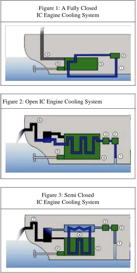
Today, most engines are liquid-cooled
Figure 1: A Fully Closed IC Engine Cooling System
Figure 2: Open IC Engine Cooling System
Figure 3: Semi Closed IC Engine Cooling System
Liquid cooling is also employed in maritime vehicles (vessels, ...). For vessels, the seawater itself is mostly used for cooling. In some cases, chemical coolants are also employed (in closed systems) or they are mixed with seawater cooling.
PROPOSED SYSTEM
The main aim of the project is to design and analyze cylinder with fins, by changing the thickness of the fins, and geometry of the fin. Analyzation is also done by varying the materials of fins. Present used material for cylinder fin body is Aluminum alloy 204 which has thermal conductivity of 110 - 150 w/mk.
Our aim is to change the material for fin body by
analyzing the fin body with other materials and also
by changing the thickness.
Geometry of fins - Rectangular, Circular and Curve Shaped
Thickness of fins - 3mm and 2.5mm
Materials - Aluminum Alloy A204,
Aluminum Alloy 7075, Magnesium alloy and Beryllium.
Changing distance between fins
Steps Involved in the Project
1. Modeling
2. Transient Thermal Analysis
For modeling of the fin body, we have used
Pro-Engineer which is parametric 3D
modeling software. For analysis we have used ANSYS, which is FEA software.
Models of Cylinder Fin Body
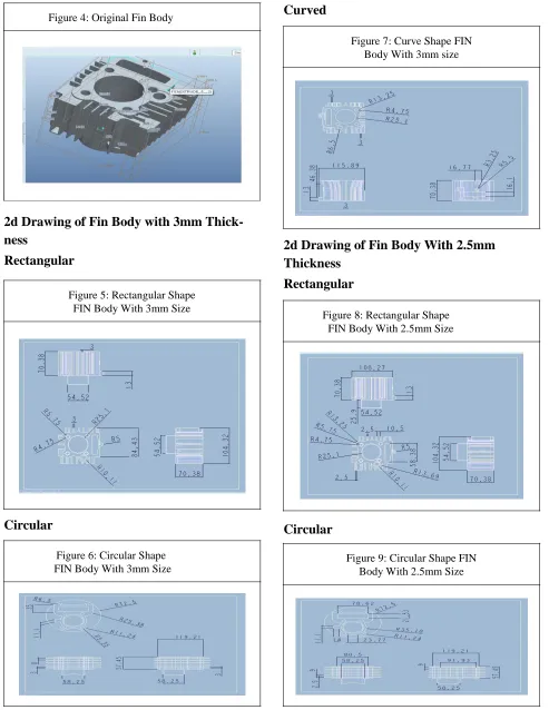
Available online: https://edupediapublications.org/journals/index.php/IJR/ P a g e | 518 Figure 4: Original Fin Body
2d Drawing of Fin Body with 3mm Thick-ness
Rectangular
Figure 5: Rectangular Shape FIN Body With 3mm Size
Circular
Figure 6: Circular Shape FIN Body With 3mm Size
Curved
Figure 7: Curve Shape FIN Body With 3mm size
2d Drawing of Fin Body With 2.5mm Thickness
Rectangular
Figure 8: Rectangular Shape FIN Body With 2.5mm Size
Circular
Available online: https://edupediapublications.org/journals/index.php/IJR/ P a g e | 519 Curved
Figure 10: Curve Shape FIN Body With 2.5mm Size
THERMAL ANALYSIS OF FIN
BODY WITH 3MM THICKNESS
Material Properties
Thermal Conductivity - 120 w/mk
Specific Heat - 0.963 J/g ºC
Density - 2.8 g/cc
Figure 11: Rectangle Shaped Aluminum Alloy 204 Meshed Model With 3mm Thickness
LOADS
Internal area=5585K
Convections - Remaining areas-Film Co- ef-ficient - 25 W/mmK
Bulk Temperature - 313 K
RESULTS OF RECTANGLE FIN
BODY WITH 3MM THICKNESS
Aluminum Alloy 204
Material Properties
Thermal Conductivity - 120 w/mk
Specific Heat - 0.963 J/g °C
Density - 2.8 g/cc
Nodal Temperature
Figure 12: Rectangle Shaped Aluminum Alloy 204 at Nodal Temperature With 3mm t
The temperature is maximum inside the cylinder with value of 530.778K and decreasing to outside with 476.333K and is still reducing on the fins.
Magnesium
Material Properties
Thermal Conductivity - 159 w/mk
Specific Heat - 1.45 J/g ºC
Density - 2.48 g/cc
Available online: https://edupediapublications.org/journals/index.php/IJR/ P a g e | 520 Figure 13: Rectangle Shaped Magnesium at Nodal
Temperature With 3mm Thickness
The temperature is maximum inside the cylinder with value of 530.778K and decreasing to outside with 476.333K and is still reducing on the fins.
Aluminum Alloy 7075
Material Properties
Thermal Conductivity - 173 w/mk
Specific Heat - 0.960 J/g °C
Density - 2.7 g/cc
Nodal Temperature
Figure 14: Rectangle Shaped Aluminum Alloy 7075 at Nodal Temperature With 3mm t
The temperature is maximum inside the cylinder with value of 530.778K and decreas-ing to outside with 476.333K and is still re-ducing on the fins.
Beryllium
Material Properties
Thermal Conductivity - 216 w/mk
Specific Heat - 0.927 J/g °C
Density - 1.87 g/cc
Nodal Temperature
Figure 15: Rectangle Shaped Beryllium at Nodal Temperature With 3mm Thickness
The temperature is maximum inside the cylinder with value of 530.778K and decreasing to outside with 476.333K and is still reducing on the fins.
RESULTS OF RECTANGLE FIN
BODY WITH 2.5MM THICKNESS
Aluminum Alloy 204
Available online: https://edupediapublications.org/journals/index.php/IJR/ P a g e | 521 Figure 16: Rectangle Shaped Aluminum Alloy 204
With Nodal Temperature With 2.5mm t
The temperature is maximum inside the cylinder with value of 530.768K and decreasing to outside with 476.304K and is still reducing on the fins.
Magnesium
Nodal Temperature
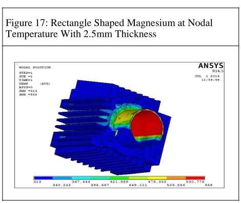
Figure 17: Rectangle Shaped Magnesium at Nodal Temperature With 2.5mm Thickness
The temperature is maximum inside the cylinder with value of 530.778K and decreas-ing to outside with 476.333K and is still re-ducing on the fins.
Aluminum Alloy 7075
Nodal Temperature
Figure 18: Rectangle Shaped Aluminum Alloy 7075 at Nodal Temperature With 2.5mm t
The temperature is maximum inside the cylinder with value of 530.778K and decreas-ing to outside with 476.333K and is still re-ducing on the fins.
Beryllium
Nodal Temperature
Figure 19: Rectangle Shaped Beryllium at Nodal Temperature With 2.5mm Thickness
The temperature is maximum inside the cylinder with value of 530.778K and decreasing to outside with 476.333K and is still reducing on the fins.
RESULTS OF CIRCULAR FIN BODY
WITH 3MM THICKNESS
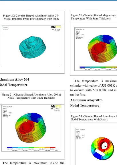
Available online: https://edupediapublications.org/journals/index.php/IJR/ P a g e | 522 Figure 20: Circular Shaped Aluminum Alloy 204
Model Imported From pro/ Engineer With 3mm
Figure 22: Circular Shaped Magnesium at Nodal Temperature With 3mm Thickness
Aluminum Alloy 204
Nodal Temperature
Figure 21: Circular Shaped Aluminum Alloy 204 at Nodal Temperature With 3mm Thickness
The temperature is maximum inside the cylinder with value of 549.311K and decreasing to outside with 531.932K and is still reducing on the fins.
Magnesium
Nodal Temperature
The temperature is maximum inside the cylinder with value of 551.001K and decreasing to outside with 537.003K and is still reducing on the fins.
Aluminum Alloy 7075
Nodal Temperature
Figure 23: Circular Shaped Aluminum Alloy 7075 at Nodal Temperature With 3mm t
Available online: https://edupediapublications.org/journals/index.php/IJR/ P a g e | 523 Beryllium
Nodal Temperature
Figure 24: Circular Shaped Beryllium at Nodal Temperature With 3mm Thickness
The temperature is maximum inside the cylinder with value of 552.588K and decreasing to outside with 541.763K and is still reducing on the fins.
RESULTS OF CIRCULAR FIN BODY
WITH 2.5MM THICKNESS
Aluminum Alloy 204
Nodal Temperature
Figure 25: Circular Shaped Aluminum Alloy 204 at Nodal Temperature With 2.5mm Thickness
The temperature is maximum inside the cylinder with value of 548.999K and decreas-ing to outside with 530.997K and is still re-ducing on the fins.
Magnesium
Nodal Temperature
Figure 26: Circular Shaped Magnesium at Nodal Temperature With 2.5mm Thickness
The temperature is maximum inside the cylinder with value of 550.732K and decreasing to outside with 536.197K and is still reducing on the fins.
Aluminum Alloy 7075
Nodal Temperature
Available online: https://edupediapublications.org/journals/index.php/IJR/ P a g e | 524
The temperature is maximum inside the cylinder with value of 552.384K and decreas-ing to outside with 541.151K and is still re-ducing on the fins.
Beryllium
Nodal Temperature
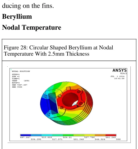
Figure 28: Circular Shaped Beryllium at Nodal Temperature With 2.5mm Thickness
The temperature is maximum inside the cylinder with value of 551.262K and decreas-ing to outside with 537.786K and is still re-ducing on the fins.
RESULTS OF CURVED FIN BODY
WITH 3MM THICKNESS
Model Imported From Pro/Engineer
Figure 29: Curve shaped Aluminum Alloy 204 model imported from pro/ engineer with 3mm
Aluminum Alloy 204
Nodal Temperature
Figure 30: Curve Shaped Aluminum Alloy 204 at Nodal Temperature With 3mm Thickness
The temperature is maximum inside the cylinder with value of 553.186K and decreasing to outside with 543.558K and is still reducing on the fins.
Magnesium
Nodal Temperature
Figure 31: Curve Shaped Magnesium at Nodal Temperature With 3mm Thickness
Available online: https://edupediapublications.org/journals/index.php/IJR/ P a g e | 525 Aluminum Alloy 7075
Nodal Temperature
Figure 32: Curve Shaped Aluminum Alloy 7075 at Nodal Temperature With 3mm Thickness
The temperature is maximum inside the cylinder with value of 554.227K and decreasing to outside with 528.218K and is still reducing on the fins.
Beryllium
Nodal Temperature
Figure 33: Curve Shaped Beryllium at Nodal Temperature With 3mm Thickness
The temperature is maximum inside the cylinder with value of 554.956K and decreas-ing to outside with 548.867K and is still re-ducing on the fins.
RESULTS OF CURVED FIN BODY
WITH 2.5MM THICKNESS
Aluminum Alloy 204
Nodal Temperature
Figure 34: Curve Shaped Aluminum Alloy 204 at Nodal Temperature With 2.5mm Thickness
The temperature is maximum inside the cylinder with value of 552.627K and decreas-ing to outside with 541.882K and is still re-ducing on the fins.
Magnesium
Nodal Temperature
Available online: https://edupediapublications.org/journals/index.php/IJR/ P a g e | 526
The temperature is maximum inside the cylinder with value of 553.793K and decreas-ing to outside with 545.379K and is still re-ducing on the fins.
Aluminum Alloy 7075
Nodal Temperature
Figure 36: Curve Shaped Aluminum Alloy 7075 at Nodal Temperature With 2.5mm Thickness
The temperature is maximum inside the cylinder with value of 554.784K and decreasing to outside with 548.351K and is
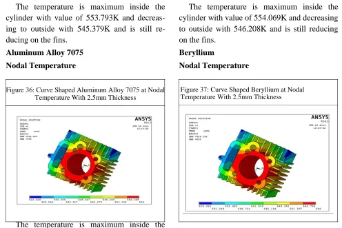
The temperature is maximum inside the cylinder with value of 554.069K and decreasing to outside with 546.208K and is still reducing on the fins.
Beryllium
Nodal Temperature
Figure 37: Curve Shaped Beryllium at Nodal Temperature With 2.5mm Thickness
still reducing on the fins.
EXPERIMENTAL RESULTS
Results and Discussions
Table 1: Results and Discussions
Fin Thickness Type Materials Results
Nodal Thermal Heat
Temperature Gradient Flux
Curved Al 7075 558 21.7453 3.76193
Al 204 558 30.034 3.604
beryllium 558 17.7891 3.84244
magnesium 558 2.73671 0.435137
2.5 mm Circular Al 7075 558 2.16593 0.467841
Al 204 558 3.354 0.40253
beryllium 558 2.62442 0.454025
magnesium 558 2.663 0.423381
Rectangular Al 7075 558 182.998 23.0087
Available online: https://edupediapublications.org/journals/index.php/IJR/ P a g e | 527
2.5 mm beryllium 558 132.021 28.5166
magnesium 558 140.767 22.3819
Curved Al 7075 558 2.39 0.413
Al 204 558 3.537 0.424496
beryllium 558 1.96731 0.42278
magnesium 558 2.763 0.439357
Circular Al 7075 558 2.12 0.366
Al 204 558 2.99 0.359345
beryllium 558 1.74111 0.377375
magnesium 558 2.3772 0.377
Rectangular Al 7075 558 70.7334 12.234
Al 204 558 91.6605 10.9993
beryllium 558 59.747 12.9054
magnesium 558 75.254 11.9634
GRAPHICAL REPRESENTATION
Thickness of 2.5 mmCurved
Figure 38: Results of Thermal Gradient
Rectangular
Figure 40: Results of Thermal Gradient and Heat Flux of All Materials With Rectangle Shape and Thickness of 2.5
mm
and Heat Flux of All Materials With Curve Shape and Thickness of 2.5 mm
200 150 100 Al 7075 Al 204 40
30 Al 7075
20
Al 204 10
Beryllium
0
Heat Thermal Magnesium
Flux Gradient
Circular
Figure 39: Results of Thermal Gradient and Heat Flux of All Materials With Circular Shape and Thickness of
2.5 mm
4
3.5
3
2.5 Al 7075
2 Al 204 1.5
1 Beryllium
0.5 Magnesium 0 Heat Thermal Flux Gradient 50 Beryllium 0 Magnesium
Heat Flux Thermal
Gradient
By observing the graphs, the heat flux is more for Beryllium and Aluminum alloy 7075.
Thickness of 3 mm
Curved
Figure 41: Results of Thermal Gradient and Heat Flux of All Materials With Curve Shape and Thickness of 3 mm
4
3 Al 7075
2 Al204 1 0 Beryllium
Heat Flux Thermal Magnesium
Available online: https://edupediapublications.org/journals/index.php/IJR/ P a g e | 528 Circular
Figure 42: Results of Thermal Gradient and Heat Flux of All Materials With Circular Shape and Thickness of 2.5 mm
4
3
Al 7075
2
Al 204
1
Beryllium
0
magnesium
Heat Flux
Thermal
Gradient
Rectangular
Figure 43: Results of Thermal Gradient and Heat Flux of all Materials With Rectangle Shape and Thickness of 2.5 mm 100 80 Al 7075 60
40 Al 204
20
Beryllium
0
Heat Flux Thermal
Magnesium Gradient
By observing the graphs, the heat flux is more for Beryllium and Aluminum alloy 7075.
Comparison of Thickness 2.5 mm and 3 mm
Curved
Thermal Gradient
Figure 44: Thermal Gradiant for Thickness 2.5 mm and 3 mm when curved
3.0mm Magnesium
Beryllium
2.5mm Al 204
Al 7075
0 20 40
Thermal Flux
Figure 45: Thermal Flux for Thickness 2.5 mm and 3 mm when curved
3.0 mm Magnesium
Beryllium
2.5 mm Al 204
Al 7075
0 5
By observing the graphs, the heat flux is more for 2.5mm
Circular
Thermal Gradient
Figure 46: Thermal Gradiant for Thickness 2.5 mm and 3 mm when circle
Magnesium 3.0 mm
Beryllium 2.5 mm
Al 204
Available online: https://edupediapublications.org/journals/index.php/IJR/ P a g e | 529 Thermal Flux
Figure 47: Thermal Flux for Thickness 2.5 mm and 3 mm when circle
Magnesium 3mm
Beryllium 2.5mm
Al 204
0 0.5 Al 7075
By observing the graphs, the heat flux is more for 2.5mm
Rectangular
Thermal Gradient
Figure 48: Thermal Gradiant for Thickness 2.5 mm and 3 mm when Retangular
3.0 mm Magnesium
Beryllium
2.5 mm Al 204
Al 7075 0 100 200
Thermal Flux
Figure 49: Thermal Gradiant for Thickness 2.5 mm and 3 mm when Retangular
3.0 mm Magnesium
By observing the graphs, the heat flux is more for 2.5mm.
CONCLUSION & FUTURE SCOPE
In this thesis, a cylinder fin body for a 150cc motorcycle is modeled using parametric software Pro/Engineer. The original model is changed by changing the thickness of the fins. The thickness of the original model is 3mm, it has been reduced to 2.5mm. By reducing the thickness of the fins, the overall weight is reduced.
Present used material for fin body is Aluminum Alloy 204. In this thesis, three other materials are considered which have more thermal conductivities than Aluminum Alloy
204. The materials are Aluminum alloy 7075,
Magnesium Alloy and Beryllium. Thermal analysis is done for all the three materials. The material for the original model is changed by taking the consideration of their densities and thermal conductivity.
By observing the thermal analysis results, thermal flux is more for Beryllium than other materials and also by reducing the thickness of the fin 2.5mm, the heat transfer rate is increased.
The shape of the fin can be modified to improve the heat transfer rate and can be analyzed. The use of Aluminum alloy 6061 as per the manufacturing aspect is to be considered. By changing the thickness of the fin, the total manufacturing cost is extra to prepare the new component.
2.5 mm Beryllium Al 204
REFERENCES
1. ADewan, P Patro, I Khan and P Mahanta (2009), “The Effect of Fin Spacing and 0 20 40 Al 7075
Available online: https://edupediapublications.org/journals/index.php/IJR/ P a g e | 530
2. Biermann A E and Pinkel B (1935), “Heat
Transfer from Finned Metal Cylinders in an
Air Stream”, NACA Report, No. 488.
3. Gibson A H (1920), “The Air Cooling of Petrol Engines”, Proceedings of the Institute of
Automobile Engineers, Vol. 14,
pp. 243-275.
4. M Kondak and I Shvets (1968), Thermal
Engineering.
5. Mehul S Patel and N M Vora (2014),
“Thermal Analysis of I C Engine Cylinder Fins Array Using CFD”, International Journal of Advance Engineering and Research Development, Vol. 1, No. 5, pp. 1-11.
6. Nabemoto A (1985), “Heat Transfer on a Fin
of Fin Tube”, Bulletin of the Faculty of
Engineering, Hiroshima University, (in Japanese), Vol. 33, No. 2, pp. 127-136.
7. Nabemoto A and Chiba T (1985), “Flow
Over Fin Surfaces of Fin Tubes”, Bulletin of
the Faculty of Engineering, Hiroshima University, (in Japanese), Vol. 33, No. 2,
pp. 117-125.
8. Pai B U, Samaga B S and Mahadevan K
(2003), “Experimental Investigation into the Free Air-Cooling of Air-Cooled
Cylinders”, SAE Paper.
9. Pulkit Agarwal, Mayur Shrikhande and P
Srinivasan (2011), “Heat Transfer
Simulation by CFD from Fins of an Air Cooled Motorcycle Engine under Varying Climatic Conditions”, Proceedings of the World Congress on Engineering, Vol. III, London, U.K.
10. Thornhill D and May A (1999), “An
Experimental Investigation into the Cooling of Finned Metal Cylinders”.
11. Thornhill D, Graham A, Cunnigham G,
Troxier P and Meyer R (1999), “Free Air
Stream”, SAE Paper.
12. U V Awasarmol and A T Pise (2011), “Pise
Experimental Study of Effect of Angle of Inclination of Fins on Natural Convection Heat Transfer Through Permeable Fins”, Proceedings on International Conference on