A Class of High-Rate
N/(N
+
1
)
Low-Complexity
Error-Detecting RLL Codes
Anthony G. Bessios†
Texas Instruments, Inc., Dallas, TX 75243, USA
Received 3 April 2000 and in revised form 24 August 2001
We present a new methodology for the construction of high-rate channel modulation run-length-limited RLL(0, k)codes. Simple modulation encoders and decoders are constructed, with low error propagation during decoding. They combine partial error detection capability (PED) to boost the performance of a concatenated outer Error Correction Code (ECC) (Blaum, 1991). Moreover, current systems are using low redundancy ECC, and the overall rate is mainly determined by the inner modulation code rate, which critically is to be maintained high. Code ratesRc=N/(N+1), for example, 16/17, 24/25 and higher are achievable,
with efficiency exceeding 0.94 and 0.96, respectively. The proposed fixed length block decodable codes, are generalized schemes of the typeN/(N+1) (d=0, k=[N/2])forN≥5.
Keywords and phrases:run-length-limited constrained codes.
1. INTRODUCTION
New high-rate RLL block codes are proposed in this paper.
These are(d = 0, k)codes, wheredandkdenote,
respec-tively, the minimum and maximum run-length of zeros between ones in an unprecoded channel data stream. There are several RLL codes with or without enhanced error control capabilities [1, 2, 3, 4, 5, 6, 7, 8, 9, 10]. The (d = 0, k/I)
RLL codes use gated-partition logic to achieve high rates
such as 8/9 [1] and 16/17 [2], while focusing on the k,I
(interleave) constraints. Their error detection capability is limited to the codewords non-supported by the code, as well
as to the weak constraint of k,I violations. Furthermore,
the block mapping size grows exponentially with the user
data word length N. Concatenation of conventional RLL
codes with ECC can reduce the effectiveness of the ECC, especially with a sliding block encoder/decoder subject to error propagation [3]. Thesingle-error correcting RLLcodes combine RLL with single-error correcting capability via an increase of the codewords’ minimum distancedmin, but with the adverse effect of a lower rate, such as 8/21, 8/28 [3], or 1/3 and 7/17 [4]. In [5], it was proposed that the Hamming subcode block length is kept as large as possible to avoid rate loss for a single-error correcting ECC/RLL code. In [6], redundancy based on appended parity bits is used, or access to channel-side information is possible and sufficiently long
†The author is currently with Agere Systems, Milpitas, CA 95035, USA;Email: [email protected].
codewords are assumed, to construct high rate codes with single error correction capability. Single error detecting systematic RLL codes subject to rate loss are presented
in [7], using m parity check bits to produce rates of
RC = N/(N+1+m). Finally, in [8] the error detecting
modulation codes with 3–4 times larger block length than conventional RLL of the same rate, alleviate the code rate overhead due to the appended parity, but they increase the system’s probability of error. In [8], code rate reduction is avoided by choosing the odd or the even sequences only, whichever provides sufficient number of codewords satisfy-ing constraintsd,k. Not all rates are feasible for every block length due to insufficient number of available codewords, and the obtained rates are lower than the conventional 8/9, and 16/17 RLL codes.
The new RLL/PED codes utilize both parities. Hence, the number of available codewords is increased sufficiently to
obtain RLL codes of the highest code rate N/(N+1) for
any block lengthN+1. Code rates as high as possible are required to increase the linear recording density in band-limited systems and avoid a larger bandwidth expansion fac-torBe∼RC−1. Low complexity high-rate constrained codes
were presented in [9] with smaller constraint k. The new
proposed codes are characterized by lower computational
complexity independent of the chosen blocklength N+1.
They have an increased list of error-detection conditions rather than just constraints pertaining tokonly as in [1, 2]. The block mapping is designed so that any concatenation
0]
[0d b YES b
NO
1−1 enc(·): d→{0,1}N+1
1 D b∈V?
Odd number of bit inversions, so that: c∈V
Even-weight codewords
Odd weight codewords
Even
Figure 1: The two-stage modulation encoder: (1) Convolutional pre-encoding, (2) Post-encoding: block mapping via conditional bit inversions, whereVis the set of allN+1-bit sequences any concate-nation of which satisfies constraintk.
of encoding/decoding bounds the decoding error propaga-tion within a block’s length only. Very low error propagapropaga-tion decoding is supported by the small number of manipulated bitsQ=1,2per codeword (Q=8in [9]).
In Section 2, the code construction methodology is pre-sented, with a specific construction example. In Section 3, the system performance is evaluated in relation to its capability for detection of the dominant error events (EE) in high den-sity partial response channels such as EPR4 andE2PR4, and analytical results are presented on the decoding error prop-agation properties. Finally in Section 4, conclusions on the new RLL constrained codes are drawn.
2. CODE CONSTRUCTION
2.1. The algorithm
We consider the set of all polynomials of degree N in
GF(2)[x]. Associate the data polynomiald(x)to each
data-word(d0, d1, . . . , dN−1)so thatd(x)=d0+d1x+ · · · + dN−1xN−1. Similarly, denote byc(x)=c0+c1x+· · ·+cNxN
andy(x)=y0+y1x+ · · · +yNxN, the codeword
polyno-mials of degreeN, associated to the recorded(c0, c1, . . . , cN)
and restored (y0, y1, . . . , yN) codewords, respectively.
En-coding of d(x)into codewordc(x), is taking place in two
steps (Figure 1).
Component code 1, “pre-encoding”:1,2
b(x)=(1+x)d(x) (overall parity [11]), (1)
whereb(x)is the pre-encoded polynomial of degreeNand
1Binary domain equivalent:[0d0]−−−−−−−−→−convolve1⊕D b(N+1-tuples of even weight).
2Alternatively, the same high rate can be produced if a single parity bit is appended at the end of theN-bit dataworddto produce the(N+1)-bitb
of only odd or only even parity.
y y
Figure2: The demodulation decoder.
evenweightwb. If constraintkis violated by some
concate-nations ofb, then post-encode:
Component code 2, “post-encoding”: addγ(x), to invert Qpreselectedbits in codewordbso that allcconcatenations formk-constrained sequences
0 if allbconcatenations satisfyk,
≠0 if at least one concatenation ofbviolatesk, (2)
where c(x) is the final codeword polynomial of degreeN
andevenoroddweightwc, that is,γ(x)=0orγ(x)≠ 0,
respectively.
SetIQcontainsQpredetermined positions (odd number)
for bitsbiof the pre-encoded codewordb(x). The setIQis
a function of qcritical bitspartitioningb(x), and is chosen so that constraintkis satisfied after manipulatingQbitsbi
during the post-encoding stage. The post-encoding mapping dimensionality is equal to2q, whereqout ofN+1bits are
preselected to determine thechange of an odd number of bits Q≥ 1, so that constraintkis satisfied. The changed parity keeps track of the manipulated codewordsc. Finally, the
“ar-bitrary” polynomialR(x)has the remaining terms ofb(x)
which remain unchanged.
Table1: The block mapping rules.
ξi 1 ¯bi 0
ci b¯i 1 bi
During the post-encoding stage, two types of conditional mappings are distinguished.
Qterms (odd num.) ,
Tables 1, 2
cl=b¯l, cm=b¯m, cn=b¯n.
Table2: The Encoding/Decoding equations.
Table3: Key code parameters.†
encoding:bi bi+(N/2) EncoderIQ=f (bi, bi+(N/2)) Encoding/Decoding Codeword
†Fori=0, . . . , N, cyclical shifts modulo(N+1) of thek-constraint controlling bits within the codeword’s block, generateN+1equivalent codes with respect to rate and constraintk.
Type II. Onebit is set equal to 1(Q=1):
ξi=¯bi−→γ(x)=b¯ixi
Tables 1, 2
ci=1. (4)
Decoding (see Figure 2). (1) For all odd-weight codewords reverse the inversions incurred during post-encoding:
ˆ
b(x)=y(x)+(wy mod 2)δ(x), (5)
whereˆbis the estimate ofb,wy is the weight of the received noise-distorted codewordy, andδ(x)is defined in Table 2.
(2) Divide by 1+x to find an estimate of the used
wordd:
ˆ
d(x)=(1+x)−1b(x).ˆ (6)
2.2. Construction example: 2-bit partitioning
N/(N+1) (0, k=N/2) N=8,16,24,32, . . . We assume that thecritical bitsbi, bi+(N/2)(q=2)partition
(indexi can be shifted cyclically modulo(N+1)) the pre-encodedb=[∗∗bi∗ · · ·
sents a “don’t care condition (0 or 1). The samples controlling constraint kareci−1,ci,ci+[N/2],ci+[N/2]+1,ci+[(3N+4)/4].
The 2-bit state(bibi+(N/2))determines the post-encoding
rules and the parity of the generated codeword c.
There-fore only four mappings take place independent of the block lengthN, whereas for the gated logic techniques [1, 2] the
mapping lookup-table grows exponentially withN. It is the
state (bi bi+(N/2)) that an odd number of bit inversions
is dependent upon, so that constraint k is satisfied for all possible codeword concatenations. When there is no need for post block mapping without violating the target constraint
k (allowed state), then the final codeword c preserves an
even weight. The state(yiyi+(N/2))combined withy’s
par-ity calculated by the decoder, determine the decoding rules (see Figure 3). There are many alternative choices to the above transformations with the same resulting k, that is, instead of inverting sample bi+(3N+4)/4, any other bit can be used within the bi+(N/2)+2bi+N−1range, or instead of setting bitci+(N/2)+1=1,ci+(N/2)−1could be set to1, and so forth.
The existing coupling between constraintkand the block lengthN, has implications on the phase detector updates in the PLL, that is, very large block lengthsNyield relatively loose constraintkunable to guarantee sufficiently frequent transi-tions at the phase detector. However, typical block lengths of N=8,16,32, . . .yield practicalkvalues. The target value for the constraintkdepends on the selected number of critical and manipulated bits qandQ, respectively, as well as their relative positions within the codeword. To produce a tighter constraintk, such ask=N/3, a larger number of critical bits (q >2) and/or manipulated bits (Q >3) should be used.
For the rate16/17andq=2-bit or5-bit partitioning, less than0.07%and0.01%, respectively of the codewordschave
Hamming weightwcless than4, and for more than91%of
the codewordsc, their Hamming weightswcrange between
7and13(see Figure 4). This type of Hamming weight
Allowed States Generating Even-weight Codewords
Generating Odd-weight Codewords
X1 1YZ
X0 0YZ
X0 1YZ
X1 0YZ
Decoding
Encoding
1 0 1YZ
X1 0 1Z X1 1Y∼Z
{
y i−1 yi+(N/2)+1PED via
Left Column States : b bi+(N/2)
{
i bi+(N/2)+1 bi+(3N+4)/4
X Y
Z They control:
Right Column States : yi+(N/2) yi+(N/2)+1 yi+(3N+4)/4
X Y
Z
{
yi yi−1 bi−1
1) Parity 2) Bit inversions
Type II Type II
Type I
ResetY= 0
ResetX= 0
Figure3: The state-transition diagram describing the conditional bit inversions during encoding/decoding;X,Y,Zare “don’t care values”.
0 0 3 1 43 9287235 1183611
3367 3697
7007
4961 11011
13387 13299
10923 12441
15147
9009
8019
5005 5753
20931969
637675 1331311717 1 1
0 2000 4000 6000 8000 10000 12000 14000 16000
Number of Codewords
1 3 5 7 9
11 13 15 17
Hamming weight
Figure4: Hamming-weight distribution for the2-bit (left) and5 -bit (right) partitioning codes.
2.3. Error control (PED)
Observing the signal space-partitioning by the encoding rules, derives the error-detection equations. By complement-ing the post-encodcomplement-ing rules described by (3), (4), and Table 2, the produced illegal combinations ofyi’s form the error
de-tecting conditions.Type IImapping performs error detection
under the following two three-bit conditions, while Type I
mapping eliminates the state bi = 0,bi+N/2 = 0 to form one two-bit error detecting condition. These error detection conditions capture both random and/or burst errors.
Table4: Error Detection (∗denotes a “don’t care” condition).
q=2 critical bits mapping onto the The derived error detection eqns.
bi bi+N/2 final codewordc yi−1 yi yi+N/2 yi+N/2+1
0 1 Type II:ci−1=1 0 0 1 ∗
1 0 Type II:ci+N/2+1=1 ∗ 1 0 0
0 0 Type I:ci=ci+N/2=1 ∗ 0 0 ∗
2.4. Example code of rate 8/9
Assume the user datawordd=(01001000):
(1) Encoding:b(x)=(1+x)d(x)→b=(011011000). From Table 3, and fori=2:ξ2=ξ6=ξ9=1,ξ1=¯b1=0, ξ7 = b¯7 = 1,b2 = 1,b6 = 0 ⇒ γ(x) = x7 ⇒ c(x) = b(x)⊕γ(x)→c=(011011010)recorded codeworded.
(2) Decoding:y=c=(011011010)has odd parity and y2=1,y6=0⇒δ(x)=x7⇒bˆ=y⊕δ=(011011000)⇒
ˆ
d(x)=b(x)/(ˆ 1+x)→dˆ=(01001000)restored codeword. (3) Error Control: we assume that in the presence of excessive noise levels, the value of bit y7 is changed from
Table5: The single bitNRZerrorei±1; EPR416/17(0,8);d2
min=4EEs.‡
Composite error detecting patterns;ei=ci−yi;1≤i <17
Type I error detection rules:
yi=0&yi+8=0 e Type II error detection rules:
yi−1=yi=0&yi+8=1
tected. If insteady2bit value is changed from1to0, then the
received codeword y = (010011010), and from Tables 3
and 4:ξ2=ξ6=1andy2=0⇒An error is detected.
3. PERFORMANCE EVALUATION
3.1. PED and the sequence detector’s dominant error events
All symbol errors non-supported by the code are detectable. This is not the case for channel bit errors fabricating valid
codewordsc. The number of invalid codewords equals the
number of valid codewords therefore for independent bit errors an equal probability (1/2) for detecting or miss-ing an error is bemiss-ing produced. However, in systems usmiss-ing sequence detectors or convolutional decoders (VA) there are dominant error events. Among other random error patterns, some of the sequence detector’s dominant minimum distance EEs can be captured. Without loss of generality, we define
the NRZerror sequencee = c−y. Then the NRZerrors
ei=ci−yiand the corresponding detected bit valuesyiare
related by: if ei =0 ⇒ yi = 0, or1; ifei = 1⇒ yi = 0;
if ei = −1 ⇒ yi = 1. We assume in an EPR4 system the
d2min=4EE with error sample vector [1 0−11 0−1], pro-duced by theNRZinput error vectore1i−11with first bit error at positioni:
e1i−11=ei=1, ei+1= −1, ei+2=1
, (7)
where the superscript denotes the NRZ error sequence
and the subscript denotes the first bit error position. The
detectable error patterns combine dminEEs and conditions
on certain restored bitsyj. Their probability of occurrence
Pcmp = 2−mPEE < PEE (probability of dmin EE), where m=1,2, . . . is the number of additional bitsyjin the
con-dition. Tables 5 and 6, list the conditions under which the single-bit and the tribitNRZerrors are captured to enhance thehit/misserror ratio.
The new channel coding schemes become more powerful when cascaded with an outer ECC code [12]. The decoder
observes the restored high-rate encoded binary sequencesy
and based on the encoder’s list of constraints, it either decodes a legitimate restored codewordyto the initial data wordd, orˆ it generates erasure byte(s)y(L)after a constraint violation
is detected [12]. The location Lof the erased symboly(L)
is passed from the demodulation decoder to the outer ECC decoder. Its error correcting capability is doubled by operat-ing on the erased symbols (error symbols of known location) produced by the PED scheme of the new RLL code.
3.2. Low error propagation decoding
The RLL/PED codes are better immuned to demodulator-induced error bursts than conventional RLL [1, 2]. The decoder’s feedback operation due to the polynomial divi-sion, renders the system prone to error propagation, however bounded by the block’s boundary. That feedback effect can be eliminated if during pre-encoding, instead of multiplying with 1+x, a single parity bit is appended to form either
only even, or only odd pre-encoded codewordsb. To further
reduce the decoding error propagation, the added parity bit is dropped instead of performing division by1+x.
A channel bit error does not necessarily corrupt the whole codeword, while this is not the case with conventional RLL codes (see Table 7). The decoder’s error burst length B (in bytes) depends on2properties of the EE: (1) its lengthL, and (2) its starting point L1. If the critical bits areyi,yi+[N/2]
and the channel EE starts at a positionL1> i+[N/2], then the front part of the codeword is still decoded correctly: first byte is saved for rates16/17,24/25, first and second bytes for rate32/33, and so forth. In general, the first[N/16]bytes are uncorrupted.
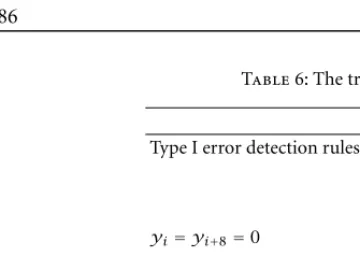
Table6: The tribit-NRZerrore±1−11i ; EPR416/17(0,8);d2
min=4EEs.#
Composite error detecting patterns;ei=ci−yi;1≤i <17
Type I error detection rules
yi=yi+8=0
Type II error detection rules
yi−1=yi=0&yi+8=1
#Note that the tribit generates the dominantd
minEE for E2PR4 systems too.
3.3. Analytical performance evaluation for the RS-RLL/PED concatenation
An analytical upper bound for the BER performance of the RLL/PED and its coding gain over the conventional RLL codes when they are concatenated with an outer ECC code, is developed in this section. This coding gain is attributed to its lower decoding error propagation and its PED capability. EE types listed in Table 8, dominate the assumed PR chan-nel with transfer function(1−D2)(1+D). Therefore, the channel output BER is upper bounded by:
channel outp. BER:pb≤
wheredis the EE distance,Kdis the multiplicity factor, and
Bavgd is the average number of byte errors per EE of distance dat the RLL decoded output derived from Table 8.
Table8: RLL rate16/17: Decoder Error Propagation.
[EE Type] (d) BRLLmin/PED−B
An ECC decoding failure occurs each time the number of RLL decoded bytes in error per block exceeds its error correcting capabilityt. Value equal to1is assigned to variable Bifor a byte in error and0otherwise. Then the ECC failure
rateFcan be evaluated as follows:
F =P Depending on the application, the two ways of exploiting the RS-RLL/PED gain are summarized in Table 9.
Analytical performance comparisons are shown in Figure 5, between RLL/PED and conventional RLL [1, 2]. At
aBER=1e−10(ECC decoded output), the RLL/PED and
Table9: ECC-RLL/PED concatenated system performance gain.
Design parameters kept constant RLL/PED advantage over RLL conventional
ECC Error Correcting capabilityt Lower RLL decoded BER (PED + lower B combined),
(same R, BW expansion, channel BER) Larger system margin (lower end BER)
End BER Smaller: overhead (t), BW expansion (lower channel BER), B
lower speed electronics (slower channel clock/sampling rate)
12 14 16 18 20 22 24
10−30 10−25 10−20 10−15 10−10 10−5 100
snr
BER
RLL decod. outp. BER (PED off) RLL decod. outp. BER (PED on) RS Failure Rate (t=8 w/ RLL conv.) channel BER conventiona @1.2814GHz
channel BER PED off @1.1135GHz channel BER PED on @1.0581GHz RLL decod. outp. BER (convent.)
Figure5: Performance comparison: RLL convent. versus RLL/PED; sameend BER; differentt,R,B.
an additional0.3dB is gained, to yield a2dB compound gain
which can be translated as an 18% clock speed savings (by
reducing the outer ECC required overhead).
4. CONCLUSIONS
A construction methodology for a new class of highly effi-cient, low complexity, RLL/PED constrained codes has been presented. The encoding, decoding, error control equations
and constraint k are expressed as simple functions of the
information block lengthN, so that afixedrate-independent
endec architecture for encoder/decoder/error-control is
accomplished, to offer: (1) very high efficiency obtained at a constant very low complexity, (2) rate adjustable codes. These properties render the codes suitable for simple implementa-tion requiring inexpensive endec circuitry. The decoder’sPED capabilityindistinguishably captures some of the single drop-in, dropout, bit-shifts as well as error bursts. The creation of composite error control patterns, capable of capturing the sequence detector’s dmin EEs, increases the probability of error detection. The new codes obtain superior perfor-mance for the concatenation of inner modulation/outer ECC decoders: If the channel errors corrupt any of theqcritical
bits, its PED capability generates erasure symbols and boosts the ECC performance; if not, then due to the decoder’s lower error propagation, most probably one or more bytes per block are still decodable therefore relaxing the ECC redundancy requirement.
ACKNOWLEDGEMENT
This research was done while the author was affiliated with Texas Instruments, Inc., Dallas, TX, USA.
REFERENCES
[1] J. Eggenberger and A. M. Patel, “Method and apparatus for implementing optimal PRML codes,” US Patent, no. 4707681, November 1987.
[2] A. M. Patel, “Rate 16/17(0,6/6) code,” IBM Tech. Discl. Bull., vol. 38, 1989.
[3] P. Lee and J. K. Wolf, “A general error-correcting code construc-tion for RLL binary channels,”IEEE Trans. Inform. Theory, vol. 35, no. 6, pp. 1330–1335, 1989.
[4] P. H. Liu and Y. Lin, “A class of(d, k)block codes with sin-gle error-correcting capability,”IEEE Trans. on Magnetics, vol. MAG-33, no. 5, pp. 2758–2760, 1997.
[6] H. C. Ferreira and S. Lin, “Error and erasure control(d, k)
block codes,” IEEE Trans. Inform. Theory, vol. 37, no. 5, pp. 1399–1408, 1991.
[7] P. N. Perry, “RLL codes for single error detection in the mag-netic recording channel,” IEEE Trans. Inform. Theory, vol. 41, no. 3, pp. 809–815, 1995.
[8] K. A. S. Immink, “Error detecting runlength-limited se-quences,” IEE Video, Audio & Data Recording.
[9] K. A. S. Immink and A. van Wijngaarden, “Simple high-rate constrained code,”Electronics Letters, vol. 32, no. 20, pp. 1877– 1877, 1996.
[10] A. G. Bessios, “Construction of low-complexity high-performancen/n+1deterministic modulation codes with adjustable codeword length and error control capability,” in
Proceedings of SPIE, San Diego, July 1998.
[11] W. W. Peterson and E. J. Weldon,Error-Correcting Codes, MIT Press, Cambridge, MA, 2nd edition, 1996.
[12] M. Blaum, “Combining ECC with modulation: performance comparison,” IEEE Trans. Inform. Theory, vol. 37, no. 3, pp. 945–949, 1991.
Anthony Bessiosreceived the B.S.E.E. from the National Technical University of Athens, Greece, in 1988 and the M.S. and Ph.D. de-grees in electrical engineering from North-eastern University, Boston, in 1990 and 1993, respectively. From 1991–1993 he was a vis-iting research assistant at the University of Southern California with the Signal and Im-age Processing Institute. In 1994 he was a visiting scientist at the National Technical