DESIGN AND SIMULATION OF THREE PHASE RECTIFIER WITH POWER FACTOR CORRECTION
MUHD HALALLUDDIN BIN ABDUL RAHIM
A thesis submitted in
fulfillment of the requirement for the award of the Degree of Master of Engineering
Faculty of Electrical & Electronic Engineering Tun Hussein Onn University of Malaysia
ABSTRACT
The Switch Mode Power Supplies (SMPS) are a multi-million dollar industry and
continuously growing industry within the field of power electronics. SMPS is widely
been used in communication, computers and industrial. The Unity Power Factor (UPF)
rectifier has become an important design issue as a consequence of recent legislation.
European legislation restricts the harmonic content of power supplies. The advantages of
UPF are more than legislative compliance. The advantages include greater efficiency,
larger power density and improved power quality result in economic benefits to the
electricity service provider. The goal of this thesis is to develop a unity power factor
rectifier. The motivation in developing this product was to develop a regulated power
supply capable of producing power with low level of harmonic current distortion. This
project observes the current, voltage waveform and also the harmonics component
before and after the compensation to the nonlinear load. In this work
MATLAB/SIMULINK power system toolbox is used to simulate the proposed system.
Simulation results are presented and the improvement in the supply current will show in
ABSTRAK
Bekalan Kuasa Mod Pensuisan merupakan industri yang menguntungkan dan
berkembang pesat secara berterusan terutamanya dalam bidang elektronik kuasa. Ianya
digunakan secara meluas dalam bidang perhubungan, komputer dan juga elektronik
kuasa. Masalah yang dihadapi oleh pereka penerus adalah kesan perlaksanaan undang –
undang terkini. Perundangan Eropah menghadkan kandungan harmonik pada bekalan
kuasa. UPF mempunyai kelebihan dalam mematuhi undang – undang tersebut. UPF juga
mempunyai kelebihan lain termasuk kecekapan, ketumpatan kuasa yang lebih besar dan
meningkatkan kualiti kuasa yang akan memberi manfaat pada ekonomi terutama kepada
pembekal perkhidmatan elektrik. Matlamat tesis ini adalah untuk membangunkan
penerus berfaktor kuasa tinggi. Motivasi menghasilkan produk ini adalah untuk
mmencipta bekalan kuasa terkawal yang mampu menghasilkan kuasa dengan tahap
herotan harmonik yang rendah. Arus, gelombang voltan dan juga komponen harmonic
sebelum dan selepas dibaiki akan diperhatikan dalam projek ini. Untuk kerja-kerja ini,
program MATLAB / Simulink digunakan untuk mensimulasi sistem yang dicadangkan.
CONTENTS
TITLE i
DECLARATION ii
DEDICATION iii
ACKNOWLEDGMENT iv
ABSTRACT v
ABSTRAK vi
CONTENTS vii
LIST OF TABLES x
LIST OF FIGURES xi
LIST OF SYMBOLS xiv
LIST OF APPENDICES xvi
CHAPTER 1 INTRODUCTION 1
1.1 Background 1
1.2 Problem Statements 3
1.3 Research Objectives 4
1.4 Research Methodology 5
1.5 Thesis Outline 7
CHAPTER 2 LITERATURE REVIEW 8
2.0 Introduction 8
2.1 Power Factor 8
2.2.1 Passive PFC 12
2.2.2 Active PFC 13
2.3 Existing Three Phase Power Converter Topologies 14
2.3.1 Rectifier Topology using Passive Input Filter 16
2.4 Boost Derived Power Converter Topologies 17
2.4.1 Six Switches Boost Power Converter 17
2.4.2 Four Switches Boost Power Converter 18
2.4.3 Three Switches Boost Power Converter 19
2.4.4 Single Switch Boost Power Converter 20
2.5 Vienna Rectifier 21
2.6 Buck Derived Power Converter Topologies 22
2.6.1 Six Switches Single-Stage Buck Power Converter 22
2.6.2 Six Switches Two-Stage Buck Power Converter 23
2.6.3 Single Switch Buck Power Converter 24
2.7 Buck Boost Converters 25
CHAPTER 3 METHODOLOGY 26
3.1 Introduction 26
3.2 Process of 3 Phase Rectifier with Power Factor Correction 27
3.3 Operating Strategy for 3 Phase Sinusoidal PWM Rectifier 28
3.3.1 Rectifying Operation 29
3.3.2 Active Filtering Operation 30
3.3.3 Generating of PWM Signals 31
3.4 Three Phase Rectifier with Active Power Filter 33
3.4.1 The Control System 35
3.4.2 DC-bus voltage Control 37
4.1 Introduction 41 4.2 System Modelling via MATLAB/Simulink 42 4.2.1 3 Phase Pulse Width Modulated (PWM) Rectifiers 42 4.2.1.1 Analysis for Three Phase PWM Rectifier 44 4.2.2 Three Phase Rectifier with Active Power Filter 45 4.2.2.1 Nonlinear Load 46 4.3 Analysis for Nonlinear Load 51
CHAPTER 5 CONCLUSIONS AND RECOMMENDATION 53
FOR FUTURE WORK
5.1 Conclusions 53
5.2 Recommendations for Future Work 54
LIST OF TABLES
4. 1 Circuit Parameters For 3 Phase PWM Rectifiers 43
LIST OF FIGURES
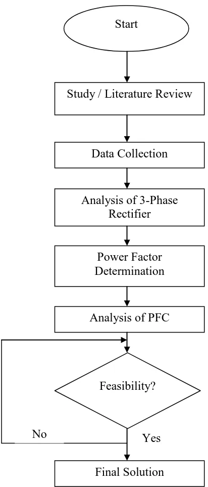
1. 1 Workflow for the research 6
2. 1 Power Factor Triangle 10
2. 2 Block Diagram of an APFC Circuit 14
2. 3 Three Phase Energy Transfer Model 16
2. 4 Rectifier Topology using Passive Input Filter 18
2. 5 Six Switches Boost Power Converter 19
2. 6 Four Switches Boost Power Converter 20
2. 7 Three Switches Boost Power Converter 21
2. 8 Single Switch Boost Power Converter 22
2. 9 Vienna Rectifier 23
2. 10 Six Switches Single-Stage Buck Power Converter 24 2. 11 Six Switches Two-Stage Buck Power Converter 25
2. 12 Single Switch Buck Power Converter 26
3. 1 Development Process 28
3. 3 Block Diagram of 3-Phase Rectifier with Active Filter 34
3. 4 Simulation in Simulink MATLAB 35
3. 5 Active Filter Controller Block Diagram 36
3. 6 PI Controller for DC-Bus Voltage Control 39
3. 7 Block Diagram of the Digital Low-Pass Filter for 40 DC Components
3. 8 Simulation in Simulink MATLAB for LPF System 40 4. 1 Three Phase Pulse Width Modulated (PWM) Rectifiers 43
4. 3 Fast Fourier Transform For PWM Rectifier 45
4. 4 Complete Simulation Model of Three Phase 46
PWM Rectifier with Active Power Filter
4. 5 Nonlinear load (Resistor) block 47
4. 6 Simulation results without compensation: load current waveform 48
4. 7 Shunt APF with Resistor Load 49
4. 8 System voltage and source current before the shunt active 50 filter starts its operation
LIST OF SYMBOLS
α - Alpha
β - Beta
APLC - Active Power Line Conditioner
APF - Active Power Filter
THD - Total Harmonic Distortion
p - Real Power
̅ - Average Active Power
̃ - Instantaneous Active Power
- Regulated Power
q - Imaginary Power
̅ - Average Reactive Power
̃ - Instantaneous Reactive Power
- Instantaneous Voltages
- Instantaneous Currents
PWM - Pulse Width Modulation
icompA, B,C - Reference currents
icompA*,B*,C * - Compensation currents
VSI - Voltage Source Inverter
PI - Proportional Integral
LPF - Low-Pass-Fiter
- DC-bus capacitor
CHAPTER 1
INTRODUCTION
1.1 Background
Power factor correction is the growing issue of concern. Within power quality framework, one of the important aspects is reactive power control. Consumer load requires reactive power that varies incessantly and increases transmission losses while affecting voltage in the transmission network. To prevent unacceptably high voltage fluctuations or the power failures that can result, this reactive power must be compensated and kept in balance. This function has always been performed by passive elements such as reactors or capacitor, as well as combination of the two that supply inductive or capacitive reactive power. The more quickly and precisely the reactive power can be compensated, the more efficiently the various characteristics of transmissions can be controlled.
from three phases or single phase mains supply. According to the relative magnitude of rectifier’s input voltage and output voltage, there is the classification of buck, boost and
buck-boost type of rectifier. Unity power factor rectifiers can also be classified as those using single switching transistor or more than one switching transistor.
As the use of energy is increasing, the requirements for the quality of the supplied electrical energy are more tighten. This means that power electronic converters must be used to convert the input voltage to a precisely regulated DC voltage to the load. Regulated DC power supplies are needed for most analog and digital electronic system. Most power supplies are designed to meet regulated output, isolation and multiple outputs.
1.2 Problem Statements
AC-DC power converters (rectifiers) are used in industry to convert an AC input voltage into a DC voltage that is either fed into a load or into another power converter. Three-phase rectifiers are preferred in high power applications because they have lower switch stresses, lower output ripple, and better power factor than single-phase rectifiers.
The AC source for almost all rectifiers is provided by the utility. There are stringent regulatory agency requirements on the harmonic content of the current that is drawn by power electronic converters to avoid the harmonic pollution of the utility voltage. These converters are therefore implemented with some sort of power factor correction (PFC) to make their input line currents more sinusoidal and in compliance with the standards.
The term power factor or PF in the field of power supplies is slightly deviate from the traditional usage of the term, which applied to reactive AC loads, such as motors powered from the AC power line. Here, the current drawn by the motor would be displaced in phase with respect to the voltage. The resulting power being drawn would have a very large reactive component and little power is actually used for producing work.
1.3 Research Objectives
The three phase rectifier with power factor correction is a method to improve the power factor near to unity, reduces harmonics distortion noticeably and automatically corrects the distorted line current. It will replace the Passive Power Factor Correction (PPFC) which has become a conventional method for the past 20 years. This research aims to implement the Unity Power Factor (UPF) for three phase rectifier which is used in designing the high-end SMPS by using APFC approach. For this purpose, a power electronic circuit is inserted between the bridge rectifier, the output filter capacitor and the load. This approach requires additional semiconductor switches and control electronics, but permits cheaper and smaller passive components.
The goals of this research are:
1. To simulate and analyze the typical power supplies.
2. To investigate the effects of low power factor to the power system. 3. To implement a three phase unity power factor rectifier.
1.4 Research Methodology
The research was carried out in two stages via analysis and experimental. The analysis starts with a literature studies which are related to the thesis topic. A completed studies and investigations were carried out on the characteristic of nonlinear loads, voltage and current distortion, total harmonic distortion, power factor and active power. In the literature survey, various topologies have been evaluated which might be able to fulfill the design specifications. Based on the literature survey, several topologies were selected for further evaluation.
In measuring power factor, harmonics in term of Total Harmonic Distortion (THD) and power ratings of different nonlinear loads, MATLAB software was used. After collecting the data and identifying the problems associated with SMPS, an active PFC circuit has been designed in order to achieve unity power factor. Finally the results were recorded and some evaluations were made.
Figure 1. 1 – Workflow for the research Start
Power Factor Determination
Final Solution Analysis of PFC Analysis of 3-Phase
Rectifier
Study / Literature Review
Data Collection
Feasibility?
1.5 Thesis Outline
The thesis is organized into 5 chapters namely the introduction, literature reviews, methodology, simulations and results analysis, conclusion and recommendation.
Chapter 1 discuss the background and general idea of the proposed project. Besides that, the objective and scope of the project are stated too in this chapter.
Chapter 2 discuss the reviews of the literature which includes the principles of technique implemented in the design of proposed rectifier. The brief reviews of the control strategy used in the proposed active power filters are mentioned in this chapter too.
Chapter 3 shows the research methodology of each design stage. The details of the topology of the proposed are discussed in this chapter with the operations of the system.
Chapters 4 displays the simulation results and analyze the compensation performance of the three-phase rectifiers subject to a typical nonlinear load. The simulation design and the results of each stage will be observed
CHAPTER 2
LITERATURE REVIEW
2.0 Introduction
The summary of results on previous research related to PFC techniques and input power factor corrected phase rectifier systems are introduced in this chapter. Numerous 3-phase PFC topologies are classified and various PFC circuits for 3-3-phase rectifiers are reviewed. The study of PFC topologies is limited to single-phase systems since most SMPS are powered by a single-phase utility source.
2.1 Power Factor
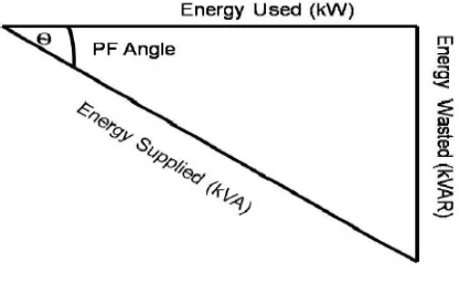
Power factor is defined as the cosine of the angle between voltage and current in an AC circuit. There is generally a phase difference θ between voltage and current in an AC circuit. cos θ is called the power factor of the circuit. It is a measure of how effectively the current is being converted into useful work output and a good indicator of the effect of the load current on the efficiency of the supply system.
Figure 2. 1 - Power Factor Triangle
In a circuit, for an input voltage V and a line current I,
– the active or real power in Watts (W),
– the reactive power in VAR ,
– the apparent power in VA,
Power factor can determined as follows:
( ) ( ) ( )
2.1.1 Benefits of Power Factor Correction (PFC)
Below are the advantages of using power factor correction circuit:
1. Electricity tariff savings.
2. Avoidance of Network Service Provider (NSP) penalties for low power factor, including restricted access to more suitable tariffs (minimum of 0.9 for large and high voltage supply establishments in most states).
3. Reduced losses.
4. Reduce power drawn from distribution systems, optimum sizing of electrical infrastructure.
5. Stabilized site voltage levels by reducing the inductive effect of the connected load.
6. The payback for PFC installations can be very reasonable and should not be over looked when considering PFC for existing installations.
Poor power factors are typically due to the effect of inductive or capacitive loads such as with a motor or with long cables providing capacitive coupling. Poor power factor due to distorted current waveforms such as with high harmonic content caused by electronic equipment cannot normally be corrected with PFC alone and will typically require complex or costly filtering [Cupertino, Marinelli].
2.1.2 Disadvantages of Low Power Factor
1. KVA rating of the electrical equipments increases due to low power factor as power factor is inversely proportional to the KVA rating of the equipment. This increases the size and cost of the equipment.
2. Conductor size increases. To transmit the same amount of power at low power factor at constant voltage needs to carry high current. So to keep the current density constant conductor area increases.
3. Copper loss of the equipment increases.
4. Voltage regulation becomes poor. Current at low lagging power factor causes greater voltage drop in alternators, transformers and transmission lines causing to have low power supply at the receiving end.
5. Handling capacity of the equipment decreases because the reactive component of current prevents the full utilization of the installed capacity.
2.2 Power Factor Correction
In view of low power factor drawbacks, some of alternatives for improving the input current waveforms are discussed along with their advantages and disadvantages. The technique used to improve the value of power factor is called Power Factor Correction (PFC) [Kneschke, T]. PFC shaped the distorted input current waveform to approximate a sinusoidal current that is in phase with the input voltage. There are several effective techniques for getting a sinusoidal input current waveform with low distortion.
On the other hand, the load power is assumed to be constant. Every single-phase PFC converter requires energy-storage (bulk) capacitor to handle difference between instantaneous input power and average output power [Bosela].
There are several approaches that have been taken by power designers to improve the value of power factor when they are designing SMPS. Most of them make used of PPFC as a solution to improve the waveform of line current in order to reduce the harmonic contents generated by SMPS. These approaches can be described as follows.
2.2.1 Passive PFC
The most common type of PFC is passive PFC. PPFC methods use additional passive components (capacitor or inductor) in conjunction with the diode bridge rectifier to correct poor power factor. A PPFC is more reliable than an APFC because no active devices are utilized. Because it operates at line frequency of 50Hz, PPFC requires relatively large fixed value inductors and capacitors to reduce the low frequency harmonic currents [Wildi]. PPFC includes passive filters which can broadly be classified into series filters, shunt filters and a hybrid combination of the two. Series filters introduce impedances in series with the utility to reduce harmonic currents. Shunt filters provide a low impedance path for the harmonic currents generated by the rectifiers so that they are not reflected in the current drawn from the utility.
2.2.2 Active PFC
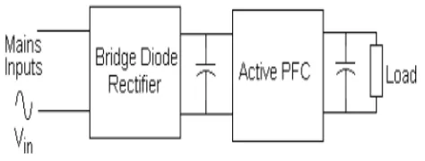
[image:23.612.211.448.393.483.2]An active power factor correction (APFC) performs much better and is significantly smaller and lighter than the PPFC circuits. An APFC refers to the use of a power electronic converter, switching at higher frequency than line frequency, to shape the input current to be sinusoidal and in-phase with the input utility voltage [Hart]. Using APFC techniques, it is possible to achieve a power factor near unity and current THD less than 5%. Despite of active wave shaping, APFC includes feedback sensing of the source current for waveform control and feedback control to regulate the output voltage even when the input voltage varies over a wide range. Compared with passive solutions, they are less bulky and can easily meet the standards of harmonic distortion [Saadat]. Figure 2.2 shows the block diagram of an APFC circuit.
Figure 2. 2 – Block Diagram of An APFC Circuit
the necessary current and power rating required. DCM is often implemented in low power design where the current ripple is lower. CCM is often preferred at high power levels.
2.3 Existing Three Phase Power Converter Topologies
A three-phase system has certain inherent advantages over a single-phase system, with the most obvious being the constant flow of power available; hence, energy storage is no longer required. A three-phase system, from a pragmatic point of view, offers more supply integrity over a single phase system. A single-phase system requires additional phase-neutral protection and is more susceptible to imbalances and harmonics [Bhavaraju, V.B]. Also, the availability of a neutral is known to be an issue in many installations.
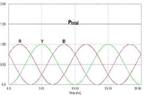
In an ideal three-phase system, there is a continuous energy transfer from source to load, and the total power transferred is the sum of the power from the three individual phases. In a three-phase system with resistive phase loads, the power drawn by each phase is given by the following formula:
Where Vp = peak input voltage and θ = phase angle. Assuming that the voltage is
unchanging;
Figure 2. 3 – Three Phase Energy Transfer Model
A number of common three-phase topologies exist that could be realized as power converter systems. Among those are the power converters that use passive input filtering in order to comply with the standard, however these do have size and weight issues making them not a very popular choice [Akagi Hirofumi]. Boost derived topologies are traditionally the topology of choice due to good current symmetry with numerous designs proposed by various authors. A disadvantage with a boost derived topology is that unless bi-directional power flow is possible the circuit suffers from inrush currents during startup conditions.
emphasis on the suitability and realization effort of each topology, with regard to usage in the power converter market.
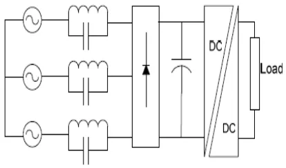
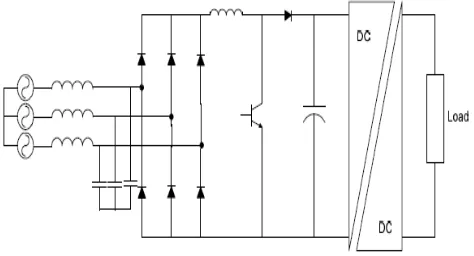
2.3.1 Rectifier Topology using Passive Input Filter
A technique that uses passive input filters is described in, the aim being to reduce the large 5th and 7th harmonic current components; this is shown in Figure 2.4. The passive elements decrease the total harmonic distortion by filtering out the low frequency harmonics, thus, improving the current waveforms drawn from the supply [Kanazawa & Nabae]. The storage capacitor is not required for energy storage, but for ripple reduction and, hence, has a reduced size compared with the single-phase passive approach.
Figure 2. 4 - Rectifier Topology using Passive Input Filter
2.4 Boost Derived Power Converter Topologies
Three-phase boost PFC power converters have traditionally been the preferred topology for high power applications due to their symmetric current drawing characteristics. A disadvantage to any boost derived topology is the inability to control startup inrush currents and output short circuit conditions, unless bi-directional power flow is possible [Grantham, Colin]. The following subsections describe various boost derived topologies.
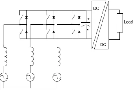
2.4.1 Six Switches Boost Power Converter
A common six switch boost converter topology has the ability to operate as a rectifier as well as an inverter due to the bidirectional power flowing capabilities. It also has good current quality and low EMI emissions [Tan, P.C]. The use of bidirectional switches also results in the ability to control the output voltage down to zero, thus, eliminating the problem that boost topologies have with regard to startup inrush currents and output short circuit protection.
and inner current loops which shape the input currents according to their sinusoidal references. The input inductors form part of the boost topology and, as such, work at the switching frequency [Granaghan]. As a result, input inductors operating at switching frequencies are smaller in size compared with line frequency input inductors.
Figure 2. 5 - Six Switches Boost Power Converter
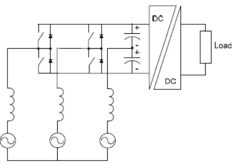
2.4.2 Four Switches Boost Power Converter
The boost derived converter shown in Figure 2.6. It has three boost inductors in the AC lines, four active switches and two series connected capacitors. The boost derived converter is capable of bi-directional power flow and, thus, is able to control the output voltage down to zero.
IEC1000-3-2 standard. However, a DC-DC converter stage is still needed to provide isolation, voltage transformation and ripple reduction.
Figure 2. 6 - Four Switches Boost Power Converter
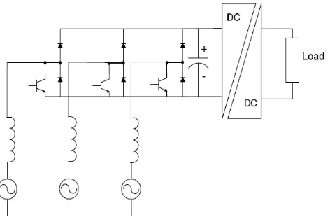
2.4.3 Three Switches Boost Power Converter
Figure 2. 7 - Three Switches Boost Power Converter
2.4.4 Single Switch Boost Power Converter
Figure 2. 8 - Single Switch Boost Power Converter
2.5 Vienna Rectifier
Another three-switch boost derived converter, also called the Vienna rectifier, is a unidirectional three-level PWM converter (Figure 2.9) and, as a result, suffers from startup inrush currents. The input stage creates a DC voltage across the two switches connected to the transformer primary.
Figure 2. 9 - Vienna Rectifier
2.6 Buck Derived Power Converter Topologies
A buck derived topology has some attractive features compared to the boost topology, such as inherent short circuit protection, easy inrush current control, and low output voltage. In addition, its input currents can be controlled in open loop, and much wider voltage loop bandwidth can be achieved. Several three-phase buck derived topologies are discussed in the following subsections.
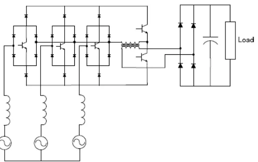
2.6.1 Six Switches Single-Stage Buck Power Converter
distribution logic. This type of converter can be implemented as a hard switched or soft switched type. This topology can meet with all the telecommunication standards. However, it has the disadvantage of requiring AC switches and a complex control system.
Figure 2. 10 - Six Switches Single-Stage Buck Power Converter
2.6.2 Six Switches Two-Stage Buck Power Converter
Figure 2. 11- Six Switches Two-Stage Buck Power Converter
2.6.3 Single Switch Buck Power Converter
The single switch buck converter, as seen in Figure 2.12, operates by having the voltages across the input capacitors discontinuous, resulting in high voltage peaks across the switch. An improved topology is introduced, which reduces the voltage stress across the switch. Using both topologies, it is possible to comply with the IEC1000-3-2 standard. However, a DC-DC converter is needed for isolation, voltage transformation and ripple reduction [Couto].
REFERENCE
Y.-Y.Hong, Y.-T.Chen, Y.-L. HSU, (May 1998). “Three-phase active power line
conditioner planning”, IEE ProcGener. Transm. Distrib., Vol. 145, No. 3
F. Cupertino, M. Marinelli, “Modelling and Design of Shunt Active Power Filter using
Genetic Algorithm”, from
http://www.scribd.com/doc/7225371/Modelling-and-Design-of-Shunt-Active-Power-Filters-Using-Genetic-Algorithms
Hirofumi Akagi, (MAY 1994). “Trends in Active Power Line Conditioners”,IEEE
Transactions on Power Electronic, VOL. 9, NO. 3, 9 (3): pp. 263-268.
(1995).Harmonic Problems and Solutions in the Industrial Environment, Electronic
Power Research Institute, Inc., from
http://www.heco.com/vcmcontent/StaticFiles/pdf/Harmonics Primer Part 1
PROTECTED.pdf
Kneschke, T.,(1999). “Distortion and Power Factor of Nonlinear Loads”. IEEE
Publication. pp. 47-54. harmonics.(n.d.). The American Heritage Science Dictionary.
Retrieved October 21, 2007, from Dictionary.com website: from http://dictionary.reference.com/browse/harmonics
Theodore R.Bosela.,(2005). ”Electrical Systems Design” Prentice Hall Upper Saddle
Theodore Wildi., (2005). “Electrical Machines, Drives and Power Systems.” Prentice
Hall Upper Saddle River, New Jersy, Fourth Edition.
Fazal A. Talukdar1, (1992 ). “Design, Analysis and Simulation of a Three- phase
Fourwire Active Power Filter and Var Compensator using MATLAB” IEEE Trans.
Power Electronics, Vol. 7 No. 1, pp. 224-229.
Daniel W. Hart.,( 1997). ”Introduction to Power Electronic”, Prentice Hall Upper Saddle River, New Jersey.
Hadi Saadat., (1999). “Power System Analysis” Milwaukee School of Engineering,
WCB McGraw-Hill.
Stephen J. Chapman.,(2005). ”Electric Machinery Fundamentals” McGraw. Hill Fourth
Edition.
Bhavaraju, V.B. Analysis and Design of some New Active Power Filter for Power
Quality Enhancement. Ph.D. Thesis. Texas A&M University.
Akagi Hirofumi. Active Filters for Power Conditioning. In Timothy L. Skvarenina. (2002). “The Power Electronics Handbook: Industrial Electronics Series.” United State
of America: CRC Press. Chap. 17:pp.30-63.
Akagi, Hirofumi. New Trends in Active Filters for Power Conditioning. IEEE
H. Akagi Y. Kanazawa, and A. Nabae. Instantaneous reactive powerc ompensators comprosing switching devices without energy storage components. IEEE Trans.
Industry Applications. 1984. l.IA (20): pp.625-630.
Patricio Salmeron and Jesus R. Vazquez, Active Power-line conditioners, University of Huelva: pp. 259-262
Grady, W. M., Samotyi, M. J. and Noyola, A. H. Survey of Active Line Conditioning Methodologies. IEEE Transactions on Power Delivery.1990. 5 (3): pp.1536 - 1542.
Huu-Phuc To, Faz Rahman and Colin Grantham, “IMPROVEMENT OF HARMONIC
REFERENCE ESTIMATION FOR SHUNT ACTIVE POWER FILTERS”, School of
Electrical Engineering and Telecommunications University of New South Wales Sydney, Australia.
Tan,P.C and Jusoh,A. , Harmonics Mitigation Using Active Power Filter A Technological Review, VOL. 8, NO. 2, 2006, pp.17-26
Mark Mc Granaghan, “ACTIVE FILTER DESIGN AND SPECIFICATION FOR
CONTROL OF HARMONICS IN INDUSTRIAL AND COMMERCIAL FACILITIES”,
Electrotek Concepts, Inc. Knoxville TN, USA
Maurício Aredes and Luís F. C. Monteiro, A Control Strategy for Shunt Active Filter, Federal University of Rio de Janeiro
Eswaran Chandra Sekaran and Ponna Nadar ,Anbalagan and Chelliah Palanisamy,
(2007). “Analysis and Simulation of a new Shunt Active Power filter using cascaded
multilevel inverter”, IEEE (ELECTRICAL ENGINEERING)VOL. 58, NO. 5, , pp.241–
249
Moleykutty George and Kartik Prasad Basu,(2008). “Three-Phase Shunt Active Power
Filter”, American Journal of Applied Sciences 5 (8): pp.909-916
JOs Arrillaga, Bruce C Smith, Neville R Watson, Alan R Wood,(October 1998). “Power
system harmonic analysis”, University of Canterbury, Christchurch, New Zealand, Wiley , p.p 1,pp.194-196.
JOs Arrillaga, Neville R Watson,(2003). ”power system Harmonics”, University of
Canterbury, Christchurch, New Zealand, Wiley, second edition, pp. 156-168
Enrique Acha, Manuel Madrigal,(2001)”Power Systems Harmonics Computer Modelling and Analysis”, Wiley, page 1-3,pp.35-43
E Acha,V.G.Agelidis,O.Anaya-Lara,T.J.E. Miller,(2002). ”Power Electronic Control in Electrical Systems”,Planta Tree,Newnes , pp. 27, 72
Fazal A. Talukdar, Sumana Choudhuri, Sujit K. Biswas, Design,( 26-28 December
2002). “Analysis and Simulation of a Three-phase Four-wire Active Power Filter and
Var Compensator using MATLAB”, Second International Conference on Electrical and
Computer Engineering ICECE 2002, Dhaka, Bangladesh
H. Doğan, R. Akkaya, (March 18 - 20, 2009).” A Simple Control Scheme for Single-
Phase Shunt Active Power Filter with Fuzzy Logic Based DC Bus Voltage Controller”,
Proceedings of the International MultiConference of Engineers and Computer Scientists
2009 Vol IIIMECS 2009, Hong Kong
Ashish Tewari,(2002). Modern Control Design with MATLAB and Simulink, British Library Cataloguing in Publication Data.
H. Dogan, R. Akkaya, (March 18 - 20, 2009). “A Simple Control Scheme for Single-
Phase Shunt Active Power Filter with Fuzzy Logic Based DC Bus Voltage Controller”,
Proceedings of the International MultiConference of Engineers and Computer Scientists 2009 Vol II IMECS 2009, Hong Kong
Moleykutty George, Kartik Prasad Basu, (2008). “Performance Comparison of Three-
Phase Shunt Active Power Filter Algorithms”, American Journal of Applied Sciences 5
(11): pp. 1424-1428
Mohan,N,Undeland, T and Robbins, W(1995). Power Electronics-Converters,
Application, and Design. 2nd.edition. Canada:John Wiley & Sons, Inc.
Hsu,C.Y. and Wu, H.-Y.A (1996). New Single-Phase Active Power Filter with Reduced
Kim, S., Yoo, G., and Song, J. (1996) Bifunctional Utility Connected Photovoltaic System with Power Factor correction and U.P.S Facility. Proceedings of the IEEE
Conference on Photovoltaic Specialist. May 13-17. Washington,