47
Design Analysis and Optimization of Industrial Lift
platform base on composite Structural sandwich plate
Miss Madhuri Rangnath Tale 1, Prof. K. R. Sontakke 2, Mr. Satav P.K.3
Department of Mechanical Engineering 1 PLITMS Buldana , PG Student’s 1,, Dean Student Associate Prof. and Head of Department2, Industrial Expert3
Email: [email protected] 1, [email protected] 2
Abstract: A structural sandwich consists of two thin face sheets made from stiff and strong relatively mild steel material welded to a thick light weight material called core made up of same material. This construction has often used in lightweight applications such as aircrafts, marine applications and wind turbine blades. In this paper the structural study of maximum type of core sandwich panel.
Keywords: Structural Analysis, ANSYS 14.5, Sandwich structure.
1. INTRODUCTION
This construction has often used in lightweight applications such as Lift, EOT crane beam, vehicle body, aircrafts, marine applications, wind turbine blades. In principle two approaches exist to develop efficient structures either application of new materials or the use of new structural design. A proven and well-established solution is the use of composite materials and sandwich structures. In this way high strength to weight ratio and minimum weight can be obtained. The sandwich structures have potential to offer a wide range of attractive design solutions. In addition to the obtained weight reduction, these solutions can often bring space savings, noise control. Laser-welded metallic sandwich panels offer a number of outstanding properties allowing the designer to develop light and efficient structural configurations for a large variety of applications. These panels have been under active investigations during the last 15 years in the world. Outokumpu has been participating in several collaborative projects in this area. In Finland the research related to all steel sandwich panels was initiated in 1988 in the Ship Laboratory of Helsinki University of Technology. The first study focused on the application of sandwich panels in the shell structures of an icebreaker. Since then in a considerable number of research projects in Finland, such as Shipyard 2000, Weld 2000 and the Kenno – Light Structures Technology Program, manufacturing, design and optimization of steel sandwich panels have been investigated. The work is based on several R&D projects driven jointly with VTT Industrial Systems, technical universities in Finland, stainless steel manufacturer Outokumpu Stainless Oy as well as Finnish sandwich panel manufacturers. In this article the results of the earlier mentioned R&D work in steel sandwich structures and applications is summarized
from the stainless steel material point of view. The research related to design and design optimization of steel sandwich panels has been summarized by Romanoff and Kujala.[5]
2. PROBLEM STATEMENT
The demand for bigger, faster and lighter moving vehicles, such as ships, trains, trucks and buses has increased the importance of efficient structural arrangements. In principle two approaches exist to develop efficient structures either application of new materials or the use of new structural design. A proven and well-established solution is the use of composite materials and sandwich structures. In this way minimum weight can be obtained. The sandwich structures have potential to offer a wide range of attractive design solutions. In addition to the obtained weight reduction, these solutions can often bring space savings, noise control. Steel sandwich panels can offer 10-25 % weight savings compared to the conventional steel structures. The work carried out includes development of design formulations for the ultimate and impact strength, analysis of strength for the joints, and development of solutions to improve the behavior under fire. A number of research projects both at the national and European level have been ongoing. A summary of the applications, main benefits and problem areas of the panels as well as available design tools are given. For weight and cost optimization is also presented proving some of the described benefits of all steel sandwich panels.
3. LITERATURE REVIEW
48
practical applications of these constructions. The results of the studies have indicated that austenitic stainless steel grade 1.4301 (AISI 304) can be used in laser welded sandwich panels offering good mechanical properties and corrosion resistance. The use of higher strength austenitic stainless steel as sandwich panels was shown to be reasonable when substantial weight reduction of load bearing structures is desired. In addition to laser welding the development of resistance and spot welding, adhesive bonding and weld-bonding processes will increase the variety of efficient techniques in manufacturing of stainless steel sandwich structures in the future. [1]
A finite element model of corrugated board containers is shown to predict the failure load of boxes, made from B- and Cboard, within an average error margin of 5%.
Effective material properties of the homogenized corrugated cores have been used, and each layer of the corrugated board is assumed to be orthotropic linear elastic. It is shown that convergence is obtained with relatively few elements, e.g. 64 elements are quite sufficient for a regular size box, i.e. 300x300x300 mm. The edge stiffness has a significant influence on the predicted failure loads because it affects the load distribution on the top and bottom edges when the side panels buckle. There is also a variation of about 10% in the failure load due to different buckling modes. This is attributed to different constraints imposed on the side panels by the corners of a box. Boxes of different sizes and board grades were tested and compared to predicted strengths. On average, the difference between experimental and predicted values was small. However, for some boxes the difference was significant because the boxes did not buckle but were crushed instead. [2] There has been a lot of research activities in Europe related to the development of laser welded steel sandwich panels. The work carried out includes the development of design formulations for the ultimate and impact strength, analysis of fatigue strength for the joints, and development of solutions to improve the behavior under fire and noise. New factories have been established to produce these types of panels, which enables larger scale implementations of the panels for various types of ships in the near future. Optimal design of steel sandwich panel applications in ships is a complex task, comprising many subtasks, such as load modelling, response calculations and optimization. Following this principle, a redesign of hoistable cardeck was performed, including the minimization of weight and cost of production. Two advanced sandwich alternatives were suggested instead of the traditional paneled structure and were then optimized. Paper gives evidence that the hoistable cardeck with sandwich paneling can now be designed in the preliminary faze without using the finite element methods. This seriously shortens the design time, which is of great importance to a designer. One optimization run, on a typical PC, took only couple of minutes, thus enabling
the variability and offering more freedom to designer to explore new concepts. [3]
A theory for the bending response of laser-welded web-core sandwich plates was developed in this thesis. The theory is suitable for the concept design of ship structures. It considers the periodic structure when the stiffness properties of a homogenized plate are derived. The plate-bending problem is solved for the homogenized plate. As a result, the deflections and internal forces are obtained for the homogenized plate. When the internal forces are known, the periodic structure is reconsidered and the discrete stresses are calculated. In addition, a method to evaluate the local stress response resulting from the application of loads directly onto the face plates was developed. When these two analyses are considered together, the total response of the web-core sandwich panel is known. It was seen that the most important stress component is caused by local patch loads. This is followed by shear-induced stresses. The normal forces and bending moments of a homogenized sandwich plate are found to have a slight influence on the total stress response. It was seen that the rigidity of the connection between the face and web plate is very important when the response is considered. This influence of the laser weld rotation stiffness was included in the formulation of the shear stiffness. The laser-welded connection transfers out-of-plane, in-out-of-plane, and moment loads to the face plates. Depending on the stiffness of the web plate and the laser weld, the moment that rotates the laser weld is transferred to the face plate. This same moment creates in-plane forces on the face plates. When the moment has a value close to zero, the web plate is not capable of transferring in-plane loads to the face plates; the thick face plate effect carries most of the load. Such a situation can occur when the web plates are very thin or the rotation stiffness of the laser weld is very small. [4]
4. OBJECTIVE OF PROJECT
Objective of this project is to increase equivalent stress strength of composite structure and also reduction of weight of composite structure as compare to conventional steel structure. For that various methods available to increase strength and reduction of weight but in this project we considered only two major parameters that have major influence on strength and reduction of weight. The objective is to increase strength by varying parameters and find the best to suit requirement and that have maximum strength and having minimum weight as compare to other conventional structure.
Following are the major objectives of Project.
1. The major objective of the proposed research work is to enhance the equivalent stress at minimum weight. 2. To propose a material which sustain maximum possible strength at minimum weight.
3. Analyse Effect of equivalent stress on composite structure.
49
5. Compare the numerical, experimental result with FEA analysis result.
5. SCOPE OF WORK
Sandwich panels are modeled in CATIA. The top and bottom plates, core parts are modeled by using CATIA. The three parts are assembled by using assembling command. Then the assembled part is saved in STP format and imported to ANSYS workbench. In ANSYS Workbench the STP format is imported and geometry will show three contact pairs. Materials properties are given to the individual part i.e, top and bottom plates are selected and mild steel properties are given to them. Now core is selected and E-glass/Epoxy. Now mesh the geometry as free mapped mesh and structural analysis is done by fixing the plate at bottom and force is applied at top face of the plate. Now by solving the structure the deflection and von misses stress are noted. By changing the corrugated core and same is modeled and analyzed the variation in deflection and von misses and weights are compared.
6. METHODOLOGY
In this project Catia is used as CAD software while ANSYS is used for analysis of equivalent stress and total deformation. The value of total deformation and equivalent stress which is getting from ANSYS software. And this value is then comparing with manual calculation as well as from experimental Universal Testing Machine. Results were recorded. Then compared Analytical and FEA analysis to conclude results.
7. ANSYS RESULT
Fig 1: Equivalent stress of Circular steel structure.
Fig 3: Equivalent stress of Triangular steel structure.
50
[image:4.595.310.541.317.484.2]Fig 2: Total deformation of Circular steel structure.
Fig 4: Total deformation of Triangular steel structure.
Fig 6: Total deformation of Rectangular steel structure.
8. RESULT TABLE
Circular Steel Structure
Sr.
No. Load(N)
Equivalent Stress (Mpa)
Deformation (mm)
Weight (Kg)
1 500 0.59117 0.0056488
0.86869 2 1000 39.029 0.011301
[image:4.595.50.252.319.481.2]3 1500 58.544 0.016952 4 2000 78.058 0.022603 5 2500 97.573 0.028254 6 3000 117.09 0.033904 7 3500 136.6 0.039555 8 4000 156.12 0.045206
Table 1: Applied Load (and obtained value of design characteristics using FEA for Circular Steel Structure
Triangular Steel Structure
Sr. No.
Load (N)
Equivalent Stress (Mpa)
Deformation (mm)
Weight (Kg)
1 500 4.3046 0.0021467
0.94672 2 1000 8.6092 0.0042934
3 1500 11.39 0.0065533 4 2000 17.218 0.0085868 5 2500 21.523 0.010734 6 3000 25.828 0.01288 7 3500 30.132 0.015027 8 4000 34.437 0.017174
Table 2: Applied Load and obtained value of design characteristics using FEA for Triangular Steel Structure
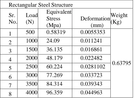
Rectangular Steel Structure
Sr. No.
Load (N)
Equivalent Stress (Mpa)
Deformation (mm)
Weight (Kg)
1 500 0.58319 0.0055353
0.63795 2 1000 24.09 0.011241
3 1500 36.135 0.016861 4 2000 48.179 0.022482 5 2500 60.224 0.0281102 6 3000 77.269 0.033723 7 3500 84.314 0.039343 8 4000 96.359 0.044963
[image:4.595.51.254.537.674.2] [image:4.595.311.541.540.709.2]51 9. UTM RESULT
Graph 1: Load Vs Deformation of Square steel structure.
0 500 1000 1500 2000 2500 3000 3500 4000 4500
0 0.01 0.02 0.03
Load
Deformation
Load Vs Deformation
Graph 2: Load Vs Deformation of Triangular steel structure.
0 500 1000 1500 2000 2500 3000 3500 4000 4500
0 0.02 0.04 0.06
Lo
ad
Deformation
Load Vs Deformation
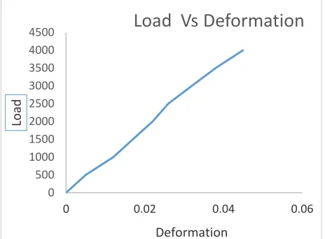
Graph 3: Load Vs Deformation of Rectangular steel structure.
10. FINAL RESULT
Graph 4:
Load Vs Deformation of steel structure.
Sr. No.
Load (N)
Circular steel Structure (Deformation)
Triangular steel Structure (Deformation)
Rectangular steel Structure (Deformation)
1 500 0.0055 0.0021 0.0056
2 1000 0.0112 0.0043 0.0113
3 1500 0.0169 0.0066 0.017
4 2000 0.0225 0.0086 0.0226
5 2500 0.0281 0.0107 0.0283
6 3000 0.0337 0.0129 0.0339
7 3500 0.0393 0.015 0.0396
[image:5.595.55.287.560.731.2]8 4000 0.045 0.0172 0.0452
Table 4: Deformation comparison of all steel structure.
52
Sr. No.
Load (N)
Circular steel Structure Equivalent Stress (Mpa)
Triangular steel Structure Equivalent Stress (Mpa)
Rectangular steel Structure Equivalent Stress (Mpa) 1 500 0.5832 4.3046 0.5912 2 1000 24.09 8.6092 39.029 3 1500 36.135 11.39 58.544 4 2000 48.179 17.218 78.058 5 2500 60.224 21.523 97.573 6 3000 77.269 25.828 117.09 7 3500 84.314 30.132 136.6 8 4000 96.359 34.437 156.12
Table 5: Equivalent Stress comparison of all steel structure.
11. CONCLUSION
The composite structure models in CATIA are efficiently imported into ANSYS workbench structural analysis is done and max stress and total deflection is observed. For given span of the structure, decreasing the weight of composite structure also the strength increases and weight is reduced. The weight of composite structure is decrease of 19-40% as compares to steel structure. And also increases the strength of composite structure as compare to steel structure.
REFERENCE
[1] DESIGNAnd Analysis of Corrugated Steel Sandwich Structures Using Ansys Workbench1A.Gopichand, 2 Dr.G.Krishnaiah, 3B.Mahesh Krishna, 4Dr.Diwakar Reddy.V, 5A.V.N.L. Sharma International Journal of Engineering Research & Technology (IJERT) Vol. 1 Issue 8, October – 2012.
[2] O.T. Thomson et al. (eds), sandwich structures 7; advancing with Sandwich structure and materials, 3-12. [3] Structural response of pyramidal core sandwich columns Francois Cote, Russell Biagi b, Hilary Bart-Smith Department of Engineering, Cambridge University, Trumpington Street, Cambridge CB2 1PZ, UK Department
of Mechanical and Aerospace Engineering, University of Virginia, 122 Engineer’s Way, Charlottesville, VA 22902, USA.
[4] Numerical simulation of steel sandwich plate System (sps) floor
A.Gopichand, 2Dr.G.Krishnaiah, 3D.Krishnaveni, 4Dr.Diwakar Reddy.VInternational Journal of Innovative Research in Science, Engineering and Technology (An ISO 3297: 2007 Certified Organization) Vol. 2, Issue11, November 2013. [5] JukkaSäynäjäkangas and TeroTaulavuori, Outokumpu Stainless Oy, Finland “A review in design and manufacturing of stainless steel sandwich panels” stainless steel world oktober 2004.
[6] Finite Element Analysis and Design of Sandwich Panels Subject to Local Buckling Effects. Narayan Pokharel1 and MahenMahendran.
[7] Penttikujala “ultimate strength analysis of all steel sandwich panels” Rakenteiden Makaniikka, vol.31 Nrot1-2, 1998, s. 32-45.
[8] Tomas Nordstrand,” Basic Testing and Strength Design of Corrugated Board and Containers” Division of Structural Mechanics, LTH, Lund University, Box 118, SE-221 00 Lund, Sweden. [9] Aydıncak, İlke” investigation of design and analyses principles of honeycomb structures”. [10] Ultimate strength analysis of all steel sandwich panels. Rakenteiden Mekaniikka vol. 31 Nrot 1-2, 1998.
[11] “Part Design & sketcher”, national institute for aviation research, Wichita State University, Revision 5.14, Copyright 2005. All rights reserved.
[12] Kirstie Plantenberg, “Introduction to CATIA V5”, Release 16, SDC publication, Schroff Development Corporation.
[13] CATIA for Designers (Evaluation Chapter F007/004), “Assembly Modeling” chapter 11 [14] “CATIA Part Design & Sketcher”, CATIA® V5R19, © Wichita State University.