R E S E A R C H
Open Access
A context-aware framework for the efficient
integration of femtocells in IP and cellular
infrastructures
Prodromos Makris
1*, Nikolaos Nomikos
1, Dimitrios N Skoutas
1, Demosthenes Vouyioukas
1, Charalabos Skianis
1,
Jie Zhang
2and Christos Verikoukis
3Abstract
In today’s heterogeneous networking (HetNet) environments, where end users are provided with universal connectivity opportunities, femtocell deployments can become key players in the enhancement of critical performance indicators such as capacity, coverage, QoS, etc. In order to confront the up-to-date LTE femtocell challenges, we propose a context-aware framework that provides a controlled environment from the femtocell point of view, which is required for applicable functionality. More specifically, we aim to (a) control the local environment where the femtocell is placed within, by efficiently managing the total incoming traffic load and by continuously adjusting the distribution of the backhaul capacity among the coexisting networks and (b) control the macro–femto interference caused by macrocell users transmitting close to the femtocell by investigating the “femtocell as a relay”concept. Finally, the performance of the proposed framework is evaluated via simulation results showing that the overall performance of a HetNet environment can be leveraged in terms of QoS requirements, energy saving and data rate enhancement.
Keywords:Context-aware, Femtocell, Relay, RRM, HetNet
1. Introduction
The Future Internet (FI) vision is expected to extend the
“Always Best Connected”(ABC) notion and include use cases according to which the FI end user will attain any service on a single intelligent device (e.g., smartphone, tablet, etc.) using any available network within a hetero-geneous network environment consisting of open, cogni-tive, and collaborative wireless and wireline networks. Towards this direction, heterogeneous networking (HetNet) deployments, proposed by 3GPP LTE-A standardization group, are expected to become a reality in the next few years, thus providing efficient ways to deal with the continuously growing traffic demand [1,2]. In contrast with the widely known cellular networks, which are based on a dedicated terrestrial backbone, the emerging femtocell technology utilizes the IP backhaul network along with small-sized base stations (BSs) [3].
Hence, the advent of femtocells added a new perspec-tive on the ABC concept as they are capable of extending cellular coverage with minimum cost by utiliz-ing an already deployed IP infrastructure. However, des-pite their mature cellular heritage, several aspects of such technology still require detailed investigation [4]. Indeed, merging the strict QoS requirements of femtocell users with the best effort IP architecture can be problematic. The main issue is the efficient sharing of the common backhaul capacity among the femtocell and other existing wireline or wireless networks [5]. As IP networks do not employ a Service Admission Control (SAC) operation, the capacity allocated to the femtocell can significantly and unpredictably fluctuate over time. Moreover, the backhaul capacity itself can also fluctuate as a result of traffic load variations at the ISP core net-work. Consequently, the performance of the femtocell operation can considerably be degraded, thus leading to inability to maintain the required QoS [6]. Current femtocell deployments address this issue by operating in closed mode, thus limiting the number of users that can * Correspondence:[email protected]
1
Department of Information and Communication Systems Engineering, University of the Aegean, Karlovassi Samos GR-83200, Greece Full list of author information is available at the end of the article
have access to the femtocell. This approach represents a low-cost and low complexity solution, which, however, can be efficient only under low traffic conditions. On the other hand, future LTE femtocells operating in a hetero-geneous and small cell network (HetSNet) environment may widely function inopenorhybridaccess modes and therefore need to handle significantly higher traffic loads [7].
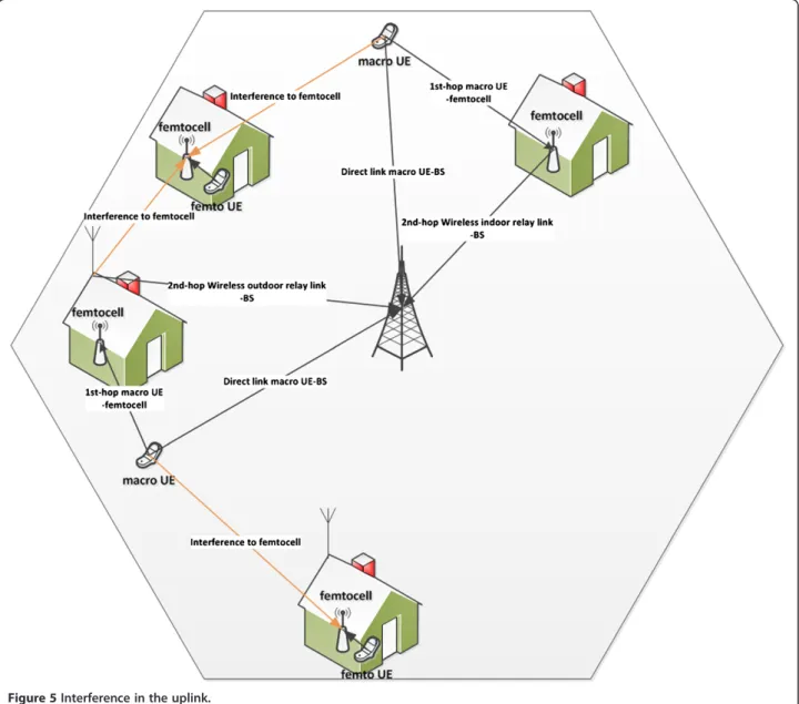
Furthermore, the unstructured placement of femtocells within a structured cellular network causes interference is-sues. In the downlink, the femto base station (BS) transmit-ting towards its femto users will interfere with the reception of nearby macro users served by the macro BS. On the other hand, in the uplink, users transmitting to-wards the macro BS may cause interference to closely lo-cated femtocells [8]. As the positioning of the femtocells cannot be controlled, the only source of interference that can actually be controlled is the transmission energy of the mobile terminals (MTs) that communicate with the macrocell BS (e.g., following femtocell as a relay concepts described in this article). Consequently, we focus on the up-link case aiming to reduce the transmission power of the macro user equipments (UEs) in order to protect the oper-ation of nearby femtocells. Towards this end, one state-of -the-art proposal is that each femtocell should serve its own interfering macro UEs [1]. Although this practice would definitely reduce interference, on the other hand it may raise privacy and QoS issues, as the femtocell owners will not always be willing to share their limited backhaul line with external users.
Based on the above considerations, we propose a context-aware framework for LTE femtocells’efficient inte-gration (CA-FEI) in IP and cellular infrastructures, which aims to provide a“shielded”environment for the femtocell operation. Our approach is twofold: (a) control the local en-vironment, where the femtocell is placed within, by effi-ciently managing the total incoming traffic load and continuously adjusting the distribution of the backhaul cap-acity among the coexisting networks. The full exploitation of femtocells’ backhaul capacity is examined following the context-aware mobile and wireless networking rationale [9] aiming to achieve more accurate and timely radio resource management (RRM) decisions and (b) to confront the up-link interference that comes from macro UEs by exploiting the use of the“femtocell as a relay” concept. We identify when a femtocell is able to act as a relay in order to assist the reduction of local interference and thus improve the QoS in other femtocells of the same region.
The remainder of the article is organized as follows: in Section 2, we cite the related work in the areas that make up the subject of our study, in Section 3, a typical system model is presented together with an outline of the proposed modifications, in Sections 4, 5, 6, and 7, the functions that should be implemented by each CA-FEI module are
presented in detail, while in Section 8, numerical results and details about the simulations are provided. Finally, con-cluding remarks are given in Section 9.
2. Related work
Several QoS considerations related to the femtocell net-work architecture have arisen and deal with the question how it is possible for the backhaul network to provide acceptable QoS [4]. The existence of net heterogeneity poses a serious concern, especially in cases where the wireline backhaul provider is not in a tight strategic rela-tionship with the cellular operator. Moreover, as femtocell access points (FAPs) are part of a continuously changing HetNet environment [1], femtocells experience difficulty transferring even low-bandwidth services.
2.1. Integration of femtocell and IP traffic
The limitations of xDSL backhaul capacity is a vital issue that needs to be addressed. Recent 3GPP standardization activities assert that it shall be possible for the network to set different criteria for access control in a hybrid cell for a closed subscriber group (CSG) and non-CSG members [10]. These different criteria incur conflicting results and this problem can be tackled by specific admission control policies, as addressed in our related work in [11]. To the best of the authors’ knowledge, there is no other work in the literature dealing with the efficient integration of femtocell and IP traffic. The proposed CA-FEI framework can be considered as complementary to [12], which pre-sents a scheme for dynamic service-level agreement negoti-ation between the ISP provider and the femtocell operator, aiming to tackle the problem of xDSL line’s varying cap-acity. In general, our proposed scheme adopts a hybrid partitioning policy [13] and can be classified within the family of admission control schemes designed for the inte-gration of heterogeneous networks, such as [14-17]. How-ever, such schemes are not directly applicable in our case as either (a) they consider significantly different system models, which in most cases include networks that have their own separate links to the core network or (b) they support basic QoS features that are not compatible with the strict QoS requirements of a femtocell.
users via the wireline backhaul. The decoder is posi-tioned at the mobile operator network and soft informa-tion is provided by the femtocell/relay to facilitate decoding. Rath et al. [19] suggest utilizing users, in the range of the femtocell, as relays of information to the macrocell UEs and conclude that with this system archi-tecture, the macrocell’s bandwidth shortage can be surpassed. Dizhi and Wei [20] elaborate on the relaying concept of [19], employing femtocells with the ability to broadcast relay service availability to the macrocell users on behalf of the femtocell users. Moreover, it is shown that the proposed architecture achieves better load bal-ancing for the macrocell and improved throughput for the macrocell users. Furthermore, in [21], mitigation schemes using femtocells with relaying capabilities are presented. Finally, the proposed scheme of [22] intro-duces femtocells that are able to decode the control channel of the macrocell BS. In this way, the femto BSs can adjust their transmissions, since they have informa-tion about the scheduled users in the macrocell avoiding inter-cell interference with the macrocell. In addition, interference cancellation is implemented at the femto-cells as an extra interference mitigation measure.
To the best of the authors’knowledge, no work studies the concept of merging classical relaying and femtocell technologies aiming to reduce the burden of the wireline backhaul. Consequently, we introduce the concept of femtocells as relays that can communicate with a wire-less backhaul with the macro BS, allocating as a result, all the available wireline backhaul to the femto UEs (see also paper’s contribution points in Section 1).
3. System architecture and proposed modifications
In the following, we will present a typical topology of a femtocell deployment, which will help us to clearly point out the proposed architectural modifications.
3.1. Typical topology of a femtocell deployment
As shown in Figure 1, the main network elements of a typical femtocell deployment are the FAP itself and a broadband IP router that allows FAP to access the Inter-net and consequently the Femtocell GateWay (FGW), which serves several FAPs. The communication between the FAP and the FGW is performed through the Iu-h interface while the Iu-Cs (Circuit switched) and Iu-Ps (Packet switched) interfaces are used for the communi-cation between the FGW and the Mobile Core Network [23]. As it also becomes apparent from the network top-ology depicted in Figure 1, the router may also serve a number of wired LAN users as well as a number of wire-less users through an attached Wi-Fi AP. Furthermore, according to the scenario being assumed, the FAP should be able to serve concurrently from 4 to 32 UEs and provide them with the same services and the same QoS as a typical Node B.
3.2. Overview of the proposed modifications
The proposed CA-FEI scheme (Figure 2) is practical, as it does not require any modifications to the existing IP infrastructure. Actually, it can be realised as an add-on unit, placed on top of the existing networks, in the form of an integrated IP Router/FAP. Furthermore, a Decode-and-Forward relay module gives the ability to this inte-grated unit to act, when possible, as a relay for the macrocell users.
3.2.1. RRM integration layer
The RRM part of CA-FEI is composed of two robust, ef-ficient and low complexity modules, which can easily be implemented and directly applied to real-market femtocell deployment scenarios. The first module is an Integrated SAC (ISAC) frontend, which is based on the effectiveness of the well-known capacity partitioning ra-tionale, while it is complemented with a novel periodic
partition adjustment (PPA) process that addresses any backhaul capacity fluctuations as well as variations of traffic load composition. Although our main concern is to preserve the QoS of delay sensitive services originat-ing from the femtocell, we also took into account that similar services may originate from other network inter-faces and, therefore, they have to be treated equally. Hence, ISAC was designed to operate over a single vir-tual network interface, thus applying the same admission policies to the total incoming traffic load. Subsequently, the capacity management (CAM) module interprets the ISAC admission decisions to the actual capacity distri-bution among the real physical network interfaces (Figure 3).
3.2.2. Context information acquisition module
The context information acquisition module (CIAM), as shown in Figure 2, acquires low-level data from the IP router and the network interfaces, and transforms them to the proper form (i.e., high-level context information) in order to be utilized as input for the SAC andCapacity Distributionmodules as well as for theRelay module(cf. Section 6). The main functionalities of CIAM regarding context acquisition are the initial set-up, monitoring,
and gathering of context. The setup phase regards the setting of the initial operating parameters, while the monitoring and gathering processes monitor the statis-tical properties of the incoming traffic load and backhaul capacity in order to adjust, if necessary, the parameters originally selected by the user and to trigger the oper-ation of the relay module.
3.2.3. Decode-and-forward relay module
An additional functionality implemented in the proposed framework is decode-and-forward relaying. Contrary to the classic setup (see Figure 1), we use wireless backhaul links towards the macro BS by adding an outdoor donor antenna connected through cable link with the femto BS. In this way, we integrate wireless relaying capabilities to the femtocells in order to protect the communication of the femtocell BS and the femto UEs using the wired backhaul link. Furthermore, as the macro UE communi-cation with the femto BS will be performed on small dis-tance links, there is an increased possibility of achieving a reduced power transmission in this part of the macrocell. This fact can lead to better SINR in other femtocells in the vicinity of the macro UE, which were not available to cooperate at that time. Also, as the Figure 2The proposed CA-FEI concept.
second hop is performed via an outdoor antenna on the rooftop of the building, there is a good chance of having LOS condition with the macro BS. As a result, the re-quired power in the second hop can also be reduced, while attaining the desired data rate in the end-to-end two-hop link.
4. SAC module
In order to perform the ISAC operation, the definition of common service classes is required for all the under-lying networks. Thus, services with similar characteris-tics, regardless of their network origin, are classified to the same integrated service group (ISG). The number of ISGs should be at least four, corresponding to conversa-tional, streaming, interactive, and background service classes as determined by 3GPP [23]. However, eachISG can be further partitioned, if a more precise cate-gorization is required. In the general case, corresponding to a total ofk ISGs, the backhaul capacity is also divided to k primary virtual partitions (VPs) and each partition Sj, 1 ≤ j ≤ kis associated to the jthISGj. An additional
(k + 1) partition, namely the Capacity Exchange (CE) partition, is also defined as required by the PPA process (cf. Section 4.2). A prerequisite for CA-FEI is that a method for indicating the QoS requirements of each traffic flow, such as DiffServ [24], should be employed at all coexisting networks. However, if a flow does not need any QoS or does not indicate that it needs a specific QoS treatment, then it will be treated as a background service (cf. Section 4.2.3).
4.1. Capacity partitioning
The aim of ISAC is to ensure that a service call with specific QoS requirements is admitted to the system only if there is adequate capacity to handle it. Conse-quently, the initial virtual capacity partitioning should be performed for the worst-case situation, where the traffic load intensity Ajoffered by each ISGj has its maximum
value, while at the same time the backhaul capacity has its minimum value Cmin. During this critical system state, the VP of the delay insensitive background ser-vices, denoted in the following as VPB, is restricted to its minimum size. Assuming that VPB is the kth parti-tion, then the partitioning problem is constrained to the firstk–1VPs.
Letajbe the average rate requested by services ofISGj,
which we assume that arrive following a Poisson process with exponentially distributed holding times. Then, the initial size Sj0of partition VPj can be defined as a
mul-tiple of aj Sj0¼mjaj;mj∈Zþ
and for a given value
of mj the blocking probability Pb,j(Aj,mj) for the
mem-bers of theISGjclass can be computed by the Erlang B
formula. IfGjis the Grade of Service(GoS) required for
ISGjservices, then the overall partitioning problem can
be described as the definition of the vectormj= (m1,m2,
Although, in the general case, the above set of equa-tions has multiple possible soluequa-tions, the initial size of the partitions can be defined through a straightforward process that ensures a reliable operation in the worst-case scenario.
(a) At first, the size of each of thek–1 partitions has to be defined in such a way that the required upper boundGjof the blocking probability of theISGj calls to be guaranteed. Therefore, as the initial size of the partitions should correspond to the
maximum acceptable blocking probability, eachSj0 can be calculated directly from Equation (1) for the case of equality (i.e.,Pb,j(Aj,mj) =Gj,∀j∈[1,
(k−1)]).
(b) Subsequently, we have to ensure that the summation of the calculated capacities Sj0 of the partitions meets the limitation of Equation (2). If not, then the network administrator has to select and prioritize those ISGs for which the target blocking probability can be further increased. The administrator has to take into account both the nature of the network and the requirements of the users so that his decision to be as tailored as possible to the specific network environment. In case the femtocell is installed by a home user, then he should be guided by a properly designed setup process in order to make the right selections based on his preferences (cf. Section 6.1). Given the
prioritized list of the selected ISGs, we iteratively follow the order of the list, and at each iteration we reduce by ajthe size of each partition Sj0 until Equation (2) is valid.
(c) Finally, if a partCLof theCmincapacity is left
unallocated after the initial partitioning process, then it is shared among thejpartitions
proportionally to their respective traffic load intensityAj. Thus, each partition is extended by a fraction ofCL, which is normalized toaj.The initial sizeSj0of each partitionVPjcan be defined as
S0
j ¼mj⋅ajþlj⋅aj¼mjþlj⋅aj ð3Þ
lj¼ Aj=
The additional capacity is calculated consecutively starting from the partition that is expected to handle the higher traffic load while ties are randomly resolved.
4.2. PPA
While the initial capacity partitioning guarantees a reli-able operation for the worst-case scenario, at the same time it could lead to capacity underutilization under normal traffic conditions. Therefore, we employ the PPA process in order to sequentially transfer unutilized cap-acity from thek–1 primaryVPsto theCEpartition and vice versa. Consequently, the VPs’size is not fixed, but instead it is adjusted in response to the variations of the traffic load composition.
4.2.1. Size of VPs
Starting from VP1 towards VPk–1, the PPA process, at time intervals of Δt, sequentially adjusts the size of all the VPs. Thus, the size Sj(t) of the VPj partition is
ad-Therefore, as implied by Equation (5), the upper bound ofSj(t) is set toSj0(cf. Equation 3)). The adjusting
functionwj(t) is equal to a negative or positive step ofaj
depending on the blocking rate Bj that the ISGj service
calls have experienced, averaged over a time interval of d seconds, and the current occupancy Οj of the
parti-tion, namely:
The higher the value of dis, the more averaged over time Bjbecomes. The guarding factorgjis a positive
in-teger (1≤ gj≤ mj), which guarantees that the size of the
partition can be decreased only if it has at least gj∙ aj
available capacity for the future incoming ISGj service
calls.
Furthermore, the size of a VP can be increased by aj
only if a corresponding decrease of the CE partition by
–aj, according to its occupancy, can be performed. If
not, the capacity adjustment of theVPis scheduled and performed asynchronously, when conditions permit to-gether with the inverse adjustment of theCE.
4.2.2. Size of the CE partition
The total capacity adjustment for theCEpartition is the negative of the summation of all the wj(t) adjustments
calculated for theVPs. Thus, the required capacitySCER (t)
for theCEpartition is
SRCEð Þ ¼t SRCEðtΔtÞ þX
However, the CE partition is not only used as a CE point between theVPs, but also acts as a common pool for all theISGs.Αs a result, the actual capacity SCE(t) of the CE partition cannot become less than the currently occupied capacityOCE(t)
SCEð Þ ¼t maxSCER ð Þt ;OCEð Þt ð8Þ
As previously mentioned, the adjustment steps, which cannot be performed due to the restriction of Equation (8), are scheduled and performed asynchronously.
4.2.3. Size of the background services virtual partition (VPB)
Based on the previous steps, the partitioning process up to this point is dimensioned on the minimum backhaul capacity Cmin. The difference between Cmin and the current value of the backhaul capacityC(t) forms theVP kfor the background services
SVPBð Þ ¼t C tð Þ Cminð Þt ð9Þ
Obviously, the background services can be accepted ei-ther at theVPBpartition or at theCEpartition.
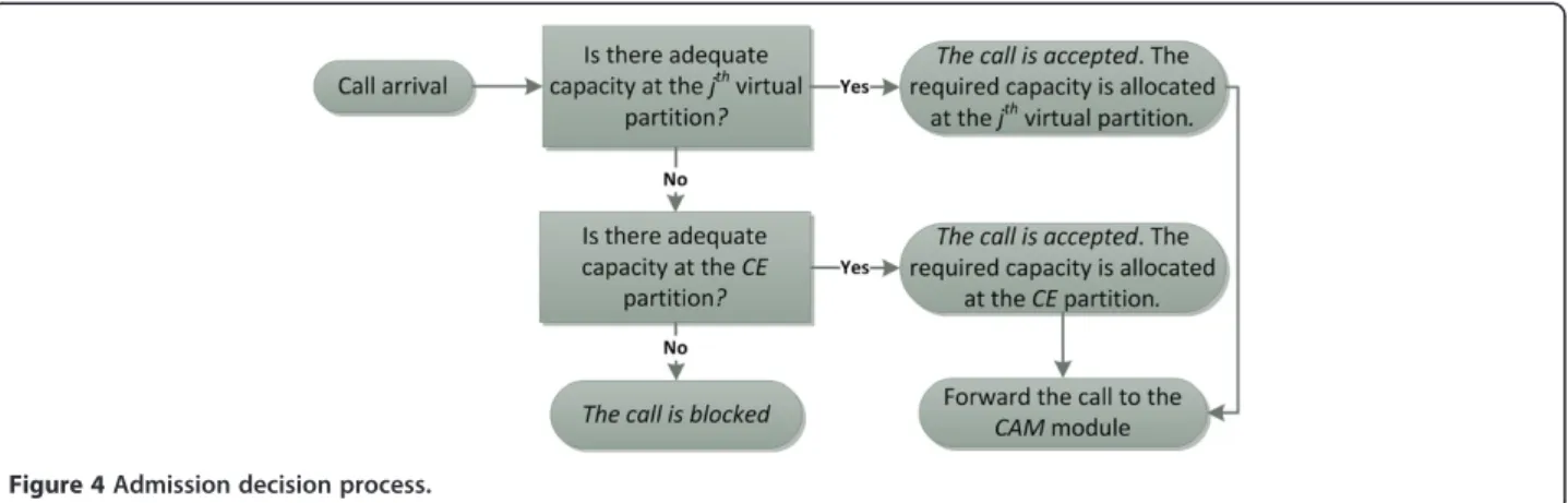
4.3. Admission decision process
As long as the virtual capacity partitions are defined, the admission decision process, as shown at Figure 4, is straightforward. An incoming service call of the ISGj is
accepted only if (a) there is an adequate free capacity at the respective jth virtual partition or else (b) if there is an adequate free capacity at the CE partition. Thus, the ISAC module ensures that (i) all service requests are handled equally irrespective of the employed network interface and that (ii) there is always adequate backhaul capacity to handle all the admitted service calls with their respective QoS requirements.
5. CAM module
The CAM module is responsible to route an admitted service call to the appropriate serving network and to adjust the backhaul capacity distribution among all the underlying networks. Specifically, assuming a total of L underlying networks (see Figure 3) each one having Ny
(1 ≤ y ≤ L) ongoing service calls of average requested rate ai (1≤ i ≤ Ny), the capacity Uy(t) allocated to each
network is defined as follows:
Uyð Þ ¼t
XNy
i¼1 ai
, XL
z¼1 XNz
i¼1 ai
!
⋅C tð Þ ð10Þ
Hence, each admitted service call modifies the fraction of the current backhaul capacity, which is allocated to each serving network. Consequently, while the ISAC module is based on the minimum value of the backhaul capacity in order to be able to guarantee a minimum QoS for all admitted service calls, the CAM module dis-tributes thetotal available backhaul capacityamong the serving networks.
In other words, although a VP may be empty and re-served for a specific ISG, its respective physical capacity does not remain unused but instead can always be uti-lized by the underlying packet schedulers, as implied by Equation (10). Therefore, it becomes clear that designing CA-FEI as a two-tier scheme makes it possible to have, at the same time, a virtual (logical) capacity distribution for the admission control process and an actual (phys-ical) capacity distribution for the serving networks. As a result, the proposed CA-FEI scheme is more flexible compared to typical one-tier schemes that utilize actual capacity partitions and thus it is able to achieve higher utilization of the backhaul capacity.
Furthermore, it can also be concluded from Equation (10) that if two networks have to serve the same traffic load, in terms of volume and distribution among the ISGs, these networks will also be allocated the same bandwidth. Consequently, the bandwidth distribution among the serving networks can be considered as fair
because it is directly proportional to their ongoing traffic load.
6. CIAM
The CIAM described in this section aims to transform low-level data acquired from the IP router and the vari-ous network interfaces intohigher-level contextinput in-formation for the RRM modules as well as for the relay module, while the latter can also provide to CIAM con-text information regarding the radio access links’quality in the vicinity of the femtocell. For example, in cases where CIAM identifies high wired backhaul capacity utilization, it can trigger the relay module to route delay sensitive traffic or traffic incurred by macro UEs via the wireless backhaul link. On the contrary, when the relay module informs CIAM that the wireless backhaul link is congested or the femtocell’s radio environment experi-ences high interference levels, CIAM can inform the RRM integration layer in order the various partitions’ capacities to be restructured in ways that efficient QoS can be achieved for all ISGs. CIAM has two main func-tionalities regarding context acquisition, which are initial set-up phase and monitoring/gathering of context.
6.1. Initial setup phase
result of this initial setup phase will serve as a basis on which the CIAM will build its future outcomes.
In cases, where the home user has to configure the ini-tial setup phase, he/she can assign priorities to specific UEs, which frequently utilize the femtocell for acquiring access to mobile services [e.g., the home user can define his/her CSG and determine the context in which a nearby macro UE can connect to the femtocell without degrading the quality of experience (QoE) of CSG’s users]. Another priority assignment procedure can take place for different service classes (e.g., the home user can define which type of services will have the highest priority and thus no QoS degradation is acceptable even in high backhaul capacity utilization situations). Given the fact that a mentality shift occurs in cellular opera-tors’ industry towards giving several motivations to femtocell owners in order their FAPs to serve more macro UEs and thus offload mobile traffic from cellular operators’infrastructure, the initial setup phase can be-come very important for the femtocell owner to experi-ence considerable bill discounts.
In cases, where ICT specialists configure the initial setup process (e.g., public access and enterprise scenar-ios analyzed in [11]), the whole procedure can become even more complicated as hybrid or open access femtocells are assumed and thus service classes’and user groups’ priorities should be configured taken into con-sideration the overall HetSNets environment.
6.2. Monitoring and gathering
During operation, the CIAM, through the monitoring and gathering processes, will keep track of the statistical properties of the incoming traffic load as well as of the backhaul capacity in order to be able to adjust, if needed, the values initially selected by the user. For example, capacity adjustments and the various partitions’ restruc-ture can happen in cases of overload-state situations or in cases when context-aware prioritization based on the type of services that the femto-relay is currently supporting, occur. More specifically, if wired backhaul experiences intolerable delays (e.g., in overload-state situations or when delay-sensitive services cannot effect-ively be delivered), then the wireless backhaul is selected, as the required QoS levels can be more easily maintained, because of the fact that the data “remains” within one cellular operator’s network.
The first sub-functionality of monitoring is the sensing of context, meaning both the detection and reception of data from sensors without introducing additional traffic overhead. Efficient scanning is a matter of vital import-ance since real-time limitations have to be satisfied and QoE objectives should be maintained within acceptable levels [9]. The key objective is the dynamic adjustment of the defined set of parameters by adopting event-based
and on-demand monitoring policies [26]. One example of monitoring is the sensing of the FAP’s radio environ-ment in order to clarify if interference levels are below some predefined and desirable thresholds. If this is the case, then the relay module can inform CIAM about the wireless backhaul link alternative and consequently the CIAM will update the wired backhaul capacity partitions (i.e., PPA process described in Section 4), so that the lat-ter can be restructured in favor of the QoS/QoE metrics for UEs. Femto-relay concept can also help in interfer-ence protection both in downlink and uplink scenarios. In downlink, a macro UE that has a weak direct link with eNB and is located in the vicinity of an open-access femto-relay can have an increased SINR if it selects to cooperate. Hence, the number of situations where two-tier interference could lead in outages can be reduced. In uplink, a macro UE that transmits with full power to maintain its connection with the eNB can instead choose a two-hop transmission through an open-access femto-relay. This cooperation will result in power reduction by the macro UE and incurred interference in nearby closed-access or non-selected femto-relays will be mitigated.
Another monitoring/gathering example is when CIAM monitors CAM and ISAC modules. More specifically, when a significant traffic load variation occurs or if the backhaul capacity utilization is relatively low or specific delay constraints for real-time services have to be met, CIAM decides the extent of wired/wireless backhaul usage based on the context information that receives from the relay module, too. Although the RRM process can dynamically be adapted to small variations of the traffic load distribution through the PPA process, the outcome of CIAM is essential for the efficiency of the RRM operation under traffic load variations taking place in larger timeframes. Equally important is the outcome of CIAM for the activation or deactivation of the relay module (cf. Section 7). More specifically, when a femtocell’s utilization is relatively low at specific time in-tervals (cf. available femtocell case depicted in Figure 5), CIAM triggers the relay module’s operation (cf. Figure 2) and thus the femtocell can act as a relay allowing neigh-boring macro UEs to transmit in a two-hop fashion.
7. Decode-and-forward relay module
UE compared to the power required for direct transmis-sion. By decreasing the transmission power, the neigh-boring femtocells, which were not available to cooperate, will experience less macro interference, too.
Moreover, in conjunction with the backhaul protection schemes analyzed in Section 4, we suggest employing outdoor donor antennas towards the macro BS, enhan-cing the femto BS with wireless relaying capabilities. This extra wireless backhaul does not replace the existing wireline backhaul but rather complements it. In this way, new possibilities for better QoS provision to delay sensitive applications as well as better interference coordination between two-tier networks are opened. The selection of outdoor antennas in the backhaul link increases the probability of having LOS conditions with the macro BS, resulting in reduced transmission power and less interference to nearby femtocells. In the case
where no outdoor antenna is installed the indoor an-tenna could be used but with increased pathloss towards the macro BS. Furthermore, by choosing to route the macro UE traffic through the wireless backhaul, further protection and better usage of the wireline backhaul capacity of the femtocells is achieved, because more cap-acity (i.e., bandwidth) is available for UEs served by the wired backhaul. More specifically, indoor users connected with a different interface to the femto BS will not have to share their backhaul capacity with UEs, which do not belong to the CSG [27].
sent to the UE together with the CSI of the femto BS-UE link. By receiving this information the BS-UE has to an-swer the following question: For the data rate required by its service, which route will provide the largest power reduction? In order for the UE to decide its uplink route, a comparison between the direct and the two-hop links is performed.
From the above description, we see that the exploit-ation of the spatial diversity provided by the deployment of femtocells could lead to a two-hop transmission re-quiring reduced transmission power compared to a dir-ect transmission towards the macro BS. As a result, having an additional path to choose from may effectively reduce the interference arising from the transmissions of the macro UE.
In our system, we assume only pathloss and log-normal shadowing effects assuming the suggested parameters in [28]. The frequency used for the commu-nication is 2 GHz, the height of the BS antenna is 32 m, while that of the RN is 10 m. For the indoor antenna we consider a height half to that of the RN at 5 m and fi-nally, the UE antenna’s height is at 1.5 m. Also, each link exhibits a different shadowing standard deviation with each case shown in Table 1. Moreover, for the link be-tween the UE and the indoor femto BS antenna, we con-sider that an additional penetration loss equal to 20 dB is added in the link budget calculations. Following the technical specifications of [28], the pathloss of the direct link between a macro UE and the macro BS is given by
PL Rð ÞUEBS¼131:1þ42:8log10ð ÞR ð11Þ
whereRis the distance in kilometers between the trans-mitter and the receiver. The shadowing standard devia-tion is equal to 10 dB. In (11), we take under consideradevia-tion the non-line-of-sight (NLOS) case, which in an urban set-ting of UEs, maintains, most of the time, NLOS connectiv-ity with the macro BS.
For the two-hop transmission, in the link between the macro UE and the cooperating femto BS, NLOS condi-tions will be dominant, as the access antennas of the femtocells will be located inside buildings. As a result, the pathloss will be [28]
PL Rð ÞUEfBS¼128:1þ37:6log10ð ÞR ð12Þ
The shadowing standard deviation has a value of 10 dB. In the second hop, when an outdoor antenna is in-stalled, the pathloss of the femto BS–macro BS link is calculated based on [28]
PL Rð ÞfBSBS¼100:7þ23:5log10ð ÞR ð13Þ
In this case, we assume line-of-sight (LOS) conditions as the outdoor antenna will be on the rooftop and di-rected towards the macro BS. The shadowing standard deviation is equal to 6 dB.
On the contrary, when no outdoor antenna is used, the link is assumed to be NLOS and the pathloss is given by [28]
PL Rð ÞfBSBS¼131:1þ42:8log10ð ÞR ð14Þ
In this link, the shadowing standard deviation has a greater value, equal to 10 dB.
8. Simulation results
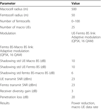
In this section, we aim to evaluate, through event driven simulation, the two main functionalities that are intro-duced by the proposed modules which are (a) the ability of the RRM integration layer to provide a predetermined QoS even under varying traffic loads and (b) the ability of the relay module to contribute to the reduction of the overall local interference. For (a), we evaluate the per-formance of the RRM integration layer through a cus-tom made event-driven simulator written in C/C++. As already referred, we assume that the incoming service requests arrive according to a Poisson process, while their duration is exponentially distributed. For (b), we followed the simulation guidelines in [28] for the devel-opment of an event-driven simulator implemented in Matlab assuming the simulation parameters shown in Table 1.
Table 1 Simulation parameters
Parameter Value
Macrocell radius (m) 500
Femtocell radius (m) 50
Number of femtocells 0–100
Number of macro UEs 25
Modulation UE-Femto BS link:
Adaptive modulation (QPSK, 16 QAM)
Femto BS-Macro BS link: Adaptive modulation (QPSK, 16 QAM)
Shadowing std UE-Macro BS (dB) 10
Shadowing std UE-Femto BS (dB) 10
Shadowing std femto BS-macro BS (dB) 6
UE transmit SNR (dBm) 23
Femto transmit SNR (dBm) 23
Receiver diversity gain (dB) 3
Penetration loss (dB) 20
Results Power reduction,
8.1. Perceived QoS under varying traffic loads
In this section, we study the ability of the CA-FEI scheme to continuously adjust to variations of the traffic load distribution. Hybrid Partitioning Schemes (HPS) and Fixed Partitioning Schemes (FPS) [13] can be con-sidered as a base of reference for comparison because their operation can be approximated, up to some point, with the currently available in the market router and femtocell combinations. However, HPS offer better cap-acity utilization and are more immune against traffic variations compared to FPS and are thus better competi-tors for the proposed CA-FEI scheme. In our case, the employed HPS has a fixed partition, defined for each service, which requires specific QoS guarantees, while the remaining capacity is utilized as common pool parti-tion for all service calls.
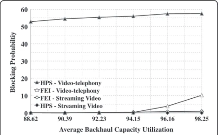
We assume a simulation scenario, where a femtocell coexists with a wire-line IP network sharing a 100-Mbps fast ethernet backhaul line. The period Δtof PPA is set to 100 ms, the guarding factor is uniformly set to 10 and the averaging time intervald is extended up to the dur-ation of the simuldur-ation (i.e., the blocking rate B is recalculated each time PPA is executed). Both CA-FEI and HPS schemes arrange their capacity partitions expecting at the worst case a 35% reduction of the backhaul capacity as well as a traffic load distribution consisting of only delay sensitive services (40% Voice, 30% Video-telephony, and 30% Streaming video) all hav-ing a targetGoSof 1%. In order to analyze the effect of PPA function, we further assume that the traffic load distribution presents an unpredictable short-term vari-ation. Thus, the percentage of video-telephony calls is increased to 50%, while the percentage of streaming video calls is decreased to 10%. The following simulation results correspond to a confidence interval of less than 5% with a confidence level of 95%.
Due to the assumed worst case scenario and the strict required GoS, the capacity left for the common pool parti-tion is significantly reduced for both HPS and CA-FEI schemes. Thus, the HPS scheme cannot cope with the un-expected variation of the traffic load. As a result, the blocking probability of video-telephony calls ranges ap-proximately between 52 and 58% when the backhaul cap-acity is highly utilized (as shown in Figure 6). At the same time, the reduced streaming video traffic makes use of a capacity partition that is initially designed to handle a sig-nificantly higher traffic volume. Consequently, streaming video calls have a zero blocking probability.
On the other hand, when the CA-FEI scheme is employed, video-telephony calls are able to utilize the capacity, which remains unused at the partition of streaming video calls. Consequently, the blocking prob-ability of video-telephony is significantly reduced com-pared to HPS and remains below the required GoS of
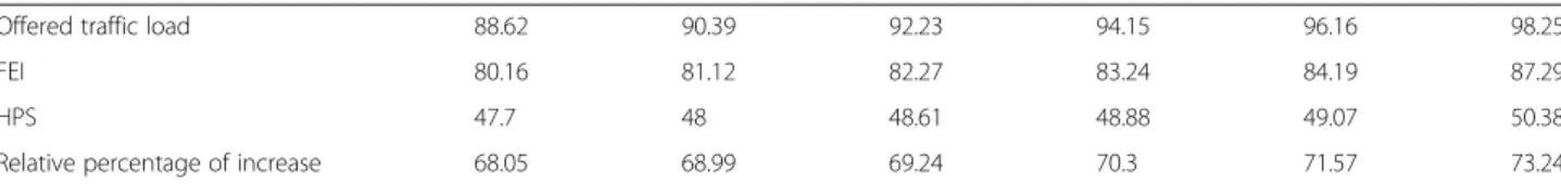
1% for traffic loads up to 94%. At the same time, due to the employed guarding factor, the blocking probability of the streaming video calls remains also below 1% at all traffic loads, even though their partition is in this case fully utilized. The efficiency of the CA-FEI scheme can also be verified at Table 2, where it is shown that CA-FEI offers increased capacity utilization compared to the HPS scheme.
In conclusion, at high traffic loads, HPS (and conse-quently FPS, used in current femtocell deployments) are inefficient in terms of capacity utilization. Hence, con-sidering the increased traffic volume expected for LTE systems, we have proposed a framework, which provides a suitable environment for the femtocell operation through effective and efficient management of the total incoming traffic and the common limited backhaul capacity.
8.2. Impact of DF relay module on the overall system’s performance
In order to study the efficiency of the proposed scheme in the uplink of a cellular network, we developed a simu-lator in Matlab considering [28] for the simulation pa-rameters. The simulation parameters are listed in Table 1. We consider a macro cell with radius 500 m op-erating in an urban environment with the macro BS lo-cated in the center and a varying number of femtocells that are available for cooperation. The macro BS is equipped with two receive antennas providing a diversity gain of 3 dB. The femtocells have a coverage radius of 50 m and are uniformly located in the macrocell. The reference receiver sensitivity values are calculated using the values in Table 22.6 of [29], considering a bandwidth of 20 MHz and the following equation [29]
REFSENS¼kTBþNFþSINRþIM
3 dBmð Þ ð15Þ
where kTB is the thermal noise level equal to −174
0
88.62 90.39 92.23 94.15 96.16 98.25
Blocking Pr
obabiltiy
Average Backhaul Capacity Utilization HPS - Video-telephony
FEI - Video-telephony FEI - Streaming Video HPS - Streaming Video HPS - Video-telephony FEI - Video-telephony FEI - Streaming Video HPS - Streaming Video
dBm/Hz, NF is the prescribed maximum noise figure for the receiver and IM is the implementation margin while −3 dB is the diversity gain. The modulation schemes range from QPSK 1/3 to 16QAM 4/5 and we use the corresponding SINR and IM values from Table 22.6 of [29].
As mentioned in Section 7, the femtocells are assumed to have an outdoor donor antenna to support the wire-less backhaul link towards the macro BS and a classic in-door coverage antenna. For simplicity, we assume NLOS conditions for UE-to-macro BS and UE-to-femto BS and LOS conditions for the femto BS-to-macro BS links. The UEs are also dropped uniformly in the macrocell area and are equipped with one transmit antenna. As a result, the maximum modulation order they can support is 16 QAM. Whenever a two-hop transmission is selected, a penetration loss of 20 dB is considered [28]. Also, over-head due to signaling when a macro UE is hand-offed from the macro BS to a femto BS and vice versa is considered negligible in the data rate results that are presented in the following paragraphs.
To evaluate the performance of the proposed scheme, we simulate the above topology to obtain numerical re-sults regarding: (a) power reduction in the transmission of the macro UEs and the backhaul antennas and (b) data rate achieved by them. For the first set of numerical results, we set a target data rate of 14.4 Mbps for the up-link as it is a reasonable value considering QoS fairness even for cell edge users. As a reference scheme is used the classic femtocell setup, where only users of the CSG are served and there is no capability to cooperate with other UEs. Results of the simulation are depicted in Figure 7 for the increasing percentage of available femtocells. Note that the values for power reduction are the differential gain of the proposed solution compare to the classic femtocell architecture.
We observe that as the available femtocells increase, there is a greater chance to achieve a transmission with reduced power by the interfering macro UEs and the backhaul antennas positioned on the roof of the build-ing. The decrease in dBm ranges from 2.9 to 9.07 dBm for the extreme case, where all the femtocells are avail-able (cf. Figure 5). For medium cooperation factors (i.e., 30–50%), we see that power reduction takes values between 4.5 and 6 dBm. As a result, to achieve the spe-cified data rate, macro interference can be reduced whenever an additional path is available to select from
(i.e., when a cooperating femtocell is near a macro UE). Moreover, the arising interference to femtocells cur-rently serving UEs of CSG will be accordingly reduced.
In the next simulation, we assume the cases of 30 and 40% availability of cooperating femtocells and we exam-ine the possibility of performing the second hop towards the macro BS through the wireline backhaul in case it can be allocated for macro UEs traffic. Figure 8 shows the results for varying percentage of wired transmissions by the cooperating femtocells for the link between the femto BS and the macro BS.
From Figure 8, we observe that for each case, if the wired backhaul is available, we completely avoid the interference in the second hop. As a result, we see an improvement over the case of only wireless backhaul, which for the case of 30% has a range between 4.4 and 6.15 dBm and for the case of 40% between 5.1 and 7.3 dBm.
In Figure 9, we present the numerical results for the data rate improvement of macro UEs in order to exam-ine whether CA-FEI scheme can provide gains in this area, compared to the classic femtocell setup. In order to explore the increase in the data rate of the macro UEs, the latter adopt a policy of selecting the best end-to-end path and transmitting with the best possible data rate. This comes in contrast to the power reduction pol-icy of the previous simulation. To measure the end-to -end capacity, we employ the half-duplex constraint in the two-hop transmission and the capacity is given by [30]
Table 2 Total capacity utilization
Offered traffic load 88.62 90.39 92.23 94.15 96.16 98.25
FEI 80.16 81.12 82.27 83.24 84.19 87.29
HPS 47.7 48 48.61 48.88 49.07 50.38
Relative percentage of increase 68.05 68.99 69.24 70.3 71.57 73.24
Ctwohop¼ 1
2min Cfirsthop;Csecondhop
ð16Þ
We see that when a macro UE receives an availability message from a femtocell with the best link, it can associ-ate with it and relay its traffic through a two-hop link. As we mentioned before, the two-hop route will be selected, when the direct link’s data rate is below the two-hop’s one. Hence, by exploiting spatial diversity, the macro UEs can improve their data rate by 26% in the extreme case of 100% available femtocells. For more realistic cases of 30–50% femtocell availability, the improvement can range between 10 and 16%. We note that these values are the relative improvement achieved with our scheme compared to the classic femtocell setup.
Finally, we study the case where an outdoor antenna for the wireless backhaul is not always available. As one of the main benefits of femtocell deployment is their plug and play nature, studying the effectiveness of femtocell cooperation in cases where outdoor antennas are available in realistic percentages will give us an indi-cation of the usefulness of the CA-FEI scheme. More specifically, Figure 10 presents the data rate performance of macro UEs in the cases of 30 and 40% availability of cooperating femtocells for a varying percentage of in-stalled outdoor antennas.
We see that macro UEs can benefit from femtocell co-operation in cases where the wireless backhaul is sup-ported by outdoor antennas. When no outdoor antennas are available, data rate sees almost no improvement due to the low transmit power of the femtocell and the pene-tration loss. On the other hand, when outdoor antennas are added to the network, we see significant improve-ment even for percentages below 50%. In the low per-centage range, we observe that data rate increases between 1.3 and 5.5% for 30% femtocell availability,
while for 40% femtocell availability, we see an increase of 1.8 to 6.7% compared to the case of only direct trans-mission in the uplink. Again, the above percentages are relative improvement compared to the reference case of the classic femtocells without wireless backhaul.
9. Conclusions and future work
This article elaborates on aspects of the recently intro-duced communication paradigm of HetSNets, which cur-rently constituted the study item of 3GPP LTE-Advanced releases. Among a plethora of research issues examined in the HetSNets area, we dealt with open challenges such as the femtocells’ limited backhaul capabilities and the macrocell/femtocell cooperation by proposing networking resources and interference management solutions from the femtocell point of view. Therefore, a novel context-aware framework for the efficient integration of femtocells in IP and cellular infrastructures, called CA-FEI, is pro-posed. CA-FEI exploits context-aware mobile and wireless networking principles thus providing a controlled archi-tectural environment, in which a femtocell is able to func-tion properly. Simulafunc-tion results show that CA-FEI outperforms competitive schemes used in real-market
Figure 8Power reduction for varying percentage of wired transmissions for the cases of 30 and 40%
femtocell availability.
Figure 9Macro UE data rate improvement for varying percentage of femtocell cooperation.
femtocell deployments regarding QoS, energy savings, and data rate enhancements achieving to (a) provide a prede-termined QoS even under varying traffic loads via the RRM integration layer and (b) contribute to the reduction of the macrocell/femtocell interference via the relay module.
Regarding business-logic threats, cost efficiency and the real-market penetration rate are the major challen-ges for the proposed femto-relay concept. Hence, the femto-relays’ manufacturing and large-scale deployment should outperform traditional deployment solutions (e.g., operator-initiated fully-fledged eNBs’ and user-initiated uncoordinated femtocells installation) in terms of OPEX/CAPEX and delivered QoS/QoE, while new business-logic research pathways and noteworthy ex-pected impact should be realized for all femto-relay beneficiaries. More specifically, cellular operators can exploit femto-relaying towards managing whole small cell networks being under their realm as a single HetSNets entity and thus be able to simultaneously tackle challenges on heterogeneous access and backhaul parts of their infrastructure. Mobile service providers can also increase their revenues by exploiting promising femto-relaying capacity gains, towards delivering novel and even more resource-consuming mobile applications. Vendors/manufacturers can benefit from developing ele-gant H/W solutions and customer-friendly small cell network products. Research and retail-oriented SMEs can also benefit from the envisioned femto-relay market growth, while citizens will be provided with a wider se-lection of mobile applications with better QoS, seamless service provisioning, and service outages minimization.
Based on the above considerations and regarding our related future work, we plan to extend the CA-FEI con-cepts applicability to larger-scale HetSNets environ-ments investigating its flexibility to various HetSNets deployment scenarios. We aim to prove that operating femtocells as relays can improve HetSNets’overall RRM objectives by extending the overall virtual backhaul link capacity in small cell areas, where excessive traffic is monitored at specific time intervals and that optimal ex-ploitation of context information among all HetSNets entities can be the cornerstone of the proposed architec-tural solutions.
Competing interests
The authors declare that they have no competing interests.
Acknowledgments
This work has been partially funded by the Research Projects GREENET (PITN-GA-2010-264759), CO2GREEN (TEC2010-20823), GREEN-T (CP8-006).
Author details
1Department of Information and Communication Systems Engineering,
University of the Aegean, Karlovassi Samos GR-83200, Greece.2Department of Electronic and Electrical Engineering, University of Sheffield, Western Bank,
Sheffield S10 2TN, UK.3Centre Tecnologic de Telecomunicacions de Catalunya (CTTC), Castelldefels, Barcelona, Spain.
Received: 29 June 2012 Accepted: 31 January 2013 Published: 5 March 2013
References
1. D Lopez-Perez, I Guvenc, G De La Roche, M Kountouris, TQS Quek, J Zhang, Enhanced intercell interference coordination challenges in heterogeneous networks. IEEE Wirel. Commun. Mag.18(3), 22–30 (2011)
2. D Martin-Sacristan, JF Monserrat, J Cabrejas Penuelas, D Calabuig, S Garrigas, N Cardona, On the way towards fourth-generation mobile: 3GPP LTE and LTE-Advanced. EURASIP J. Wirel. Commun. (2009), 1–10 (2009). doi:10.1155/2009/354089 3. J Zhang, G De La Roche,Femtocells: Technologies and Deployment(Wiley,
New York, 2010). ISBN 978–0470742983
4. V Chandrasekhar, J Andrews, A Gatherer, Femtocell networks: a survey. IEEE Commun. Mag.46(9), 59–67 (2008)
5. O Tipmongkolsilp, S Zaghloul, A Jukan, The evolution of cellular backhaul technologies: current issues and future trends. IEEE Commun. Surv. Tutor. 13(1), 97–113 (2011)
6. P Kulkarni, WH Chin, T Farnham, Radio resource management
considerations for LTE femto cells. ACM SIGCOMM Comput. Commun. Rev. 40(1), 26–30 (2010)
7. G De, A la Roche, DL-P Valcarce, J Zhang, Access control mechanisms for femtocells. IEEE Commun. Mag.48(1), 33–39 (2010)
8. P Xia, V Chandrasekhar, JG Andrews, Open vs. closed access femtocells in the uplink. IEEE Trans. Wirel. Commun.9(12), 3798–3809 (2010) 9. P Makris, DN Skoutas, C Skianis, A survey on context-aware mobile and
wireless networking: on networking and computing environments integration. IEEE Commun. Surv. Tutor.15(1), 362–386 (2013)
10. 3GPP, LTE,Service Requirements for Home NodeBs (UMTS) and eNodeBs (LTE). 3GPP TS 22.220, V.10.3.0, Release 10, 2010
11. DN Skoutas, P Makris, C Skianis,Optimized Admission Control Scheme for Coexisting Femtocell, Wireless and Wireline Networks(Springer Telecommunication Systems, Special Issue on Mobility Management in Future Internet, 2012). in press
12. MZ Chowdhurry, S Choi, YM Jang, KS Park, Dynamic SLA negotiation using bandwidth broker for femtocell networks, inProceedings of 1st International Conference on Ubiquitous and Future Networks (ICUFN), 2009, pp. 12–15
13. A Rouskas, DN Skoutas, G Kormentzas, DD Vergados, Code reservation schemes at the forward link in WCDMA. Elsevier Comput. Commun. 27(9), 792–800 (2004)
14. R Skehill, M Barry, W Kent, M O’Callaghan, N Gawley, S Mcgrath, The common RRM approach to admission control for converged heterogeneous wireless networks. IEEE Wirel. Commun.14(2), 48–56 (2007)
15. E Stevens-Navarro, AH Mohsenian-Rad, V Wong, Connection admission control for multiservice integrated cellular/WLAN system. IEEE Trans. Veh. Technol.57(6), 3789–3800 (2008)
16. D Calabruig, JF Monserrat, DM Sacristan, N Cardona, Joint dynamic resource allocation for QoS provisioning in multi-access and multi-service wireless systems. Springer MONET15(5), 627–638 (2010)
17. N Andrews, Y Kondareddy, P Agrawal, Channel Management in Collocated WiFi-WiMAX Networks, inProceedings of 42nd Southeastern Symposium on System Theory (SSST), 2010, pp. 133–137
18. T Elkourdi, O Simeone, Femtocell as a relay: an outage analysis. IEEE Trans. Wirel. Commun.10(12), 4204–4213 (2011)
19. A Rath, S Hua, SS Panwar,FemtoHaul:Using femtocells with relays to increase macrocell backhaul bandwidth, inProceedings of INFOCOM IEEE Conference on Computer Communications Workshops, 2010, pp. 1–5
20. Z Dizhi, S Wei, Interference-controlled load sharing with femtocell relay for macrocells in cellular networks, inProceedings of Global Telecommunications Conference (GLOBECOM), 2011, pp. 1–5
21. A Tyrrell, F Zdarsky, E Mino, M Lopez, Use Cases, Enablers and requirements for evolved femtocells, inProceedings of Vehicular Technology Conference (VTC Spring), 2011, pp. 1–5
23. 3GPP,Technical Specifications Group Services and Systems Aspects; End-to-end Quality of Service (QoS) Concept and Architecture. 3GPP TS 23.107, V9.1.0, Release 9, 2010
24. S Blake, D Black, M Carlson, E Davies, Z Wang, W Weiss,An architecture for differentiated services. Internet RFC 2475, 1998
25. B Statovci-Halimi, G Franzl,QoS Differentiation and Internet Neutrality—A Controversial Issue within the Future Internet Challenge(Springer Telecommunication Systems, 2011)
26. S Kang, J Lee, H Jang, Y Lee, S Park, J Song, A scalable and energy-efficient context monitoring framework for mobile personal sensor networks. IEEE Trans. Mob. Comput.9(5), 686–702 (2010)
27. IF Akyildiz, DM Gutierrez-Estevez, E Chavarria Reyes,Femto-relay systems and methods of managing same. US Patent 20120076027, 2012, http://users.ece. gatech.edu/~dmge3/publications/patent1.pdf
28. 3GPP, Technical Specifications Group Radio Access Network,Evolved Universal Terrestrial Radio Access (E-UTRA); Further advancements for E-UTRA physical layer aspects.3GPP TR 36.814, V9.0.0, Release 9, 2010
29. S Sesia, I Toufik, M Baker,LTE The UMTS Long Term Evolution, From Theory to Practice(Wiley, New York, 2009). ISBN 978-0-470-69716-0
30. JN Laneman, DNC Tse, GW Wornell, Cooperative diversity in wireless networks: efficient protocols and outage behavior. IEEE Trans. Inf. Theory50(12), 3062–3080 (2004)
doi:10.1186/1687-1499-2013-62
Cite this article as:Makriset al.:A context-aware framework for the efficient integration of femtocells in IP and cellular infrastructures. EURASIP Journal on Wireless Communications and Networking20132013:62.
Submit your manuscript to a
journal and benefi t from:
7 Convenient online submission
7 Rigorous peer review
7 Immediate publication on acceptance
7 Open access: articles freely available online
7 High visibility within the fi eld
7 Retaining the copyright to your article