Faculty of Computer ScienceInstitute of Software- and Multimedia-Technology,Software Technology Group
Diploma Thesis
MODEL-BASED RUN-TIME
VERIFICATION OF SOFTWARE
COMPONENTS BY
INTEGRATING OCL INTO TREATY
Claas Wilke
Born April, 16th 1983 in Buxtehude Mat.-Nr.: 3155376
Supervised by:
Dr.-Ing. Birgit Demuth
ProfessorProf. Dr. rer. nat. habil. Uwe Aßmann
Submitted on September 3, 2009ABSTRACT
Model Driven Developmentis used to improve software quality and efficiency by automatically
transforming abstract and formal models into software implementations. This is particularly sen-sible if the model’s integrity can be proven formally and is preserved during the model’s transfor-mation. A standard to specify software model integrity is theObject Constraint Language (OCL). Another topic of research is the dynamic development of software components, enabling soft-ware system composition at component run-time. As a consequence, the system’s verification must be realized during system run-time (and not during transformation or compile time). Many established verification techniques cannot be used for run-time verification.
A method to enable model-based run-time verification will be developed during this work. How OCL constraints can be transformed into executable software artifacts and how they can be used in the component-based systemTreatywill be the major task of this diploma thesis.
The work contains:
• An introduction into the theoretical foundations, • An investigation of related work,
• The requirement analysis and a prototypical design of a run-time verification process, • A prototypical implementation of the designed system,
• And its validation using an example case.
CONTENTS
Abstract III 1 Introduction 1 2 Foundations 5 2.1 Verification vs. Validation . . . 5 2.1.1 Software Verification . . . 5 2.1.2 Software Validation . . . 6 2.1.3 Run-time Verification . . . 62.2 The Object Constraint Language . . . 7
2.3 The Generic Three Layer Metadata Architecture . . . 7
2.4 Two Ways to Verify Contracts at Run-time . . . 9
2.4.1 The Interpretative Approach . . . 9
2.4.2 The Generative Approach . . . 9
2.5 Dresden OCL . . . 9
2.5.1 The Dresden OCL Toolkit . . . 11
2.5.2 The Dresden OCL2 Toolkit . . . 11
2.5.3 Dresden OCL2 for Eclipse . . . 11
2.6 A Motivating Example . . . 13
2.7 The Consumer/Supplier Role Model . . . 15
2.8 Aspect-Oriented Programming . . . 20
2.9 The Eclipse/OSGi Component Model . . . 21
2.9.1 The Extension Point Schema . . . 21
2.9.2 The Plug-in.xml File . . . 22
2.10 Eclipse Equinox Aspects . . . 25
2.10.1 The Equinox Architecture . . . 25
2.10.2 The Equinox Aspects Project . . . 25
3 Run-Time Verification Approaches 27 3.1 Treaty . . . 27
3.1.1 Contract Definition . . . 28
3.1.2 Contract Vocabularies . . . 28
3.2 The CALICO Approach . . . 30
3.3 Run-Time Error Detection in the Trader Project . . . 31
3.4 The Satin Approach . . . 32
3.5 Constraint Monitoring in USE . . . 32
3.6 The RISC System . . . 33
3.7 The Java Modeling Language . . . 34
3.8 The Contracting System ConFract . . . 35
3.8.1 Requirements in ConFract . . . 35
3.8.2 The Contract Language CCL-J . . . 35
3.8.3 Contract Closure and Checking . . . 36
3.9 Snapshot Verification for CORBA components . . . 36
3.10 The PECOS Approach . . . 37
3.11 Run-time Verification in EJB . . . 37
3.12 Architectural Constraints in MADAM . . . 38
4 Analysis and Architectural Design 41
4.1 Requirement Analysis . . . 41
4.1.1 Contract Definition Requirements . . . 41
4.1.2 Contract Verification Requirements . . . 42
4.1.3 Delimited Features . . . 43
4.2 Evaluation and Decision of Required Resources . . . 43
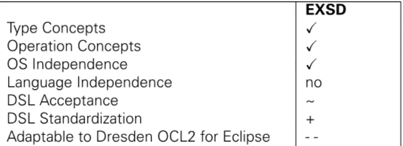
4.2.1 Possible Domain-Specific Languages . . . 44
4.2.2 Required Model Instance Types . . . 49
4.2.3 OCL Constraint Integration . . . 50
4.3 Discussion of Multiple Software Architectures . . . 52
4.3.1 Adapting the OCL2 Interpreter as a Treaty Vocabulary . . . 53
4.3.2 Generating JUnit Test Code for Treaty Using the Java Code Generator . . . 55
4.3.3 Generating Aspect Code Using the Java Code Generator . . . 56
4.3.4 Architectural Design Decision . . . 58
5 Design and Implementation 59 5.1 Refactoring of the Treaty Architecture . . . 59
5.1.1 Problems of the Current Treaty Architecture . . . 59
5.1.2 The Refactored Treaty Architecture . . . 60
5.2 Treaty OCL Vocabulary Implementation . . . 62
5.2.1 The Taxonomy of the OCL Vocabulary . . . 62
5.2.2 The Implementation of the Vocabulary Interface . . . 63
5.3 Java Meta-Model Adaptation . . . 65
5.3.1 Different Possible Adaptations . . . 65
5.3.2 The Realized Adaptation . . . 66
5.4 Context Information Capturing and Adaptation . . . 69
5.4.1 Aspect-Oriented Information Retrieval . . . 69
5.4.2 Service-Based Information Capturing . . . 71
5.5 Refactoring of Dresden OCL2 for Eclipse . . . 71
5.5.1 Changes in the Model to Model Instance Relationship . . . 73
5.5.2 Refactoring of the Model Instance Architecture . . . 77
5.5.3 Refactoring of the Java Model Instance Type . . . 77
5.5.4 Refactoring of the OCL2 Interpreter . . . 78
6 Testing 81 6.1 Testing the Treaty OCL Vocabulary . . . 81
6.2 Testing the Adapted Java Meta-Model . . . 84
6.3 Testing Snapshot Verification . . . 85
7 Evaluation and Future Works 87 7.1 Evaluation . . . 87
7.1.1 Contract Definition Requirements . . . 87
7.1.2 Contract Verification Requirements . . . 90
7.1.3 Delimited Features . . . 90
7.2 Future Works and Scientific Challenges . . . 90
7.2.1 Future Works on Treaty . . . 90
7.2.2 Future Works on the Treaty OCL Vocabulary . . . 91
7.2.3 Future Works on Dresden OCL2 for Eclipse . . . 91
7.2.4 Scientific challenges . . . 92
7.3 Summary and Conclusion . . . 93
A List of Figures XI
B List of Tables XV
C List of Listings XVII
D List of Abbreviations XIX
Bibliography XXI
1
INTRODUCTION
Even if proof techniques and tools eventually become available, one may suspect that run-time checks will not go away, if only to cope with hard-to-predict events such as hardware faults, and to make up for possible bugs in the proof software itself [...]
Betrand Meyer [Mey97, p. 399]
Since programming has lead to source code being too large to be structured in a single file in a readable way, software engineers have been trying to structure their software more efficiently. In the 1970s,Software Modules[Par72] became popular to structure software more intelligent, readable and secure. Examples for modular programming languages areModula-2,Delphi,Pascal
and Ada-83 [Aßm03, p. 64f]. The next step towards powerful programming languages was
Object-oriented Programming[Mey97] which organizes the software modules in a more intuitive
and logical way and introduces the concept of object initialization at run-time. Examples for object-oriented programming languages areADA-95,Sather,C++andJava[Aßm03, p. 3].
Software Components[Szy02] can be used “to encapsulate data and programs into [boxes] that
operate[s] predictable [BJPW99].” Software components can be considered as a higher program-ming paradigm than object-oriented programprogram-ming, because they improve modularity, interface standardization and provide more dynamic connection mechanisms [Aßm03, p. 67]. According to Szyperski [Szy02, p. 35ff], a software component is a unit of independent deployment that is well separated from its environment and other components and can be of third-party composition. A software component has no (externally) observable state and encapsulates its implementation. It communicates with the environment via well-defined interfaces. A software component can be loaded into and activated in a particular system. Software components are highly modular and interchangeable. “[...] one component may replace another even if it has a different internal implementation, as long as its specification includes he interfaces that the client component re-quires.” [LC02, Sect. 1] Components of that only the interfaces are visible are calledBlackbox
Components. Components that provide also access to their internal structure are called
White-box Componentsinstead. Also hybrid components, so-calledGraybox Componentsexist [Szy02,
p. 544ff]. In this work the termComponentwill represent blackbox components.
Component-Based Software Engineering (CBSE)is becoming a mainstream approach. The
ad-vantages of CBSE are quicker development times, secure investments through reuse of existing components and the ability to compose software interactively [GZ01]. Component-based soft-ware is portable, interoperable, extensible, configurable and maintainable [LSNA97]. A central question in CBSE is how to trust foreign or third-party components. Beugnard [BJPW99] points out that mission-critical systems cannot be rebooted easily if an error occurs during their run-time
and some components may behave unexpectedly. Thus, we have to determine whether we can trust and use given components before and during component interaction. We need the ability to verify that software components conform to their specification [Hei03], some sort of high-quality specifications in the middle, often calledContracts[Szy00]. A contract “[...] protects the client by specifying how much should be done [... and] the contractor by specifying how little is acceptable [...]” [Mey92, p. 41] Contracts are a well-known mechanism for achieving trustworthy software [ABH+06, Mey97].
Traditionally, collaborations in component models are described by interface compatibility [DJ08]. “Technically an interface is a set of operations that can be invoked by clients.” [Szy02, p. 50] An interface defines which methods are provided and required by a component to interact with other components. Such interfaces can be regarded as syntactic contracts. “The notion of con-tracts as interfaces–annotated with pre- and postconditions and, perhaps, invariants–is simple and practical. However several important issues are not covered.” [Szy02, p. 55] Besides, in-terface compatibility contracts can be defined on properties of software instances. Changes of object states at run-time can invalidate properties and contracts at run-time [ABH+06, p. 155]. Contracts defined on properties of instances can be considered asDynamic Contracts[ABH+06, p. 157]. In modern component systems components can be dynamically discovered, loaded, started, terminated and unloaded.
Thus, other types of contracts are required as well. “[... C]ontracts need to go far beyond establishing functional requires and provides clauses.” [Szy00] Beugnard [BJPW99] separates component contracts into four categories:
1. Basic Syntactic Contracts: Syntactic contracts define the interfaces components pro-vide to communicate with other components. Traditionally, a description language like the
Interface Definition Language (IDL)or an object-oriented programming language likeJava
can be used to define such interfaces.
2. Behavioral Contracts:Besides the interface definition, the component user has to ensure that the used component does what the component is expected to do. “You can never be sure the component will perform correctly, only that it will perform as specified.” [BJPW99] Thus, behavioral contracts are used to define the component semantics. Typically, such
Design by Contract[Mey97, p. 331ff] is realized by defining pre- and postconditions in
con-straint languages likeEiffel[ECM06] or theObject Constraint Language (OCL)[OMG06c]. “The client has to establish the precondition before calling the operation and the provider can rely on the precondition being met whenever the operation is called. The provider has to establish the postcondition before returning to the client and the client can rely on the postcondition being met whenever the call to the operation returns.” [Szy02, p. 53]
3. Synchronization Contracts:In multi-user scenarios or distributed systems synchronization contracts are used to ensure that the components communicate in the right order. Paral-lelism, and sequences of method execution can be defined. Synchronization in terms of transactional behavior can be realized as well.
4. Quality of Service Contracts: A fourth group of contracts defines Quality of Service
(QoS) requirements that are commonly known as Non-Functional or Extra-Functional
re-quirements. E.g., QoS contracts can define response times or result throughputs for multi-object answers.
Dietrich [DJ08] names some other types of contracts besides the four categories depicted by Beugnard, includingSecurity,TrustandLicensing. Aßmann et al. [ABH+06] point out that con-tracts defined on software connections can be separated inSimpleand Multi-Point Contracts. Simple contracts focus on one extension or connection of components whereas multi-point con-tracts focus on combinations of extensions.
As mentioned above, one possibility to design behavioral contracts is the Object Constraint
Language (OCL)[OMG06c]. A tool for supporting OCL constraints defined on models in different
Domain-Specific Languages (DSLs)(e.g., UML or EMF Ecore) isDresden OCL2 for Eclipse. A
con-tract system to define functional and non-functional constraints on software components and to evaluate them at component run-time is provided by the contract languageTreaty[DJ08, URL09s]. This work presents an approach to extend the contracting language Treaty with the definition of OCL constraints by combining Dresden OCL2 for Eclipse with Treaty. It is examined how OCL can be used for run-time verification of behavioral contracts on components. A solution that is independent of the underlying component language and implementation is presented.
This work is structured as follows: Chapter 2 introduces some foundations like the Object Con-straint Language (OCL) and presents a motivating example for the definition of behavioral con-straints using OCL. Chapter 3 discusses related work and systems that have already been trying to realize run-time verification on component systems or have investigated similar research tasks. Chapter 4 analyses the requirements and discusses different architectural designs that could be used to combine Dresden OCL2 for Eclipse and Treaty. In Chapter 5 some implementation details are documented and explained. Chapter 6 illustrates how the implementation presented in this work has been tested. Chapter 7 finishes the work by shortly summarizing and evaluating the presented work and highlighting some challenges for future works.
Typographical and graphical conventions used in this work:
• Italicsare used to highlight important keywords and scientific terms.
• Typewriter font is used to sign model elements or language constructs of different programming and modeling languages such as Java or OCL.
• Small typewriter font is used to show coding examples in listings.
• Small, blue, bold typewriter font is used to highlight keywords in listings.
• Small, red typewriter font is used to highlight strings in listings. • Small, green typewriter font is used to highlight comments in listings.
• Blue coloris used to denote hyperlinks between references.
• Class diagrams and component models are illustrated according to theUnified Modeling
Language (UML) [OMG09c]. A good introduction into UML can be found in the book
UML@Work by Martin Hitz et al. [HKKR05] and in The Unified Modeling Language
Ref-erence Manualby James Rumbaugh et al. [RJB04].
• The illustration of role models was inspired by Riehle et al. [RG98].
2
FOUNDATIONS
The difference between “theory” and “practice” is that in theory there is no difference between theory and practice, but in practice, there is.
Jan L. A. van de Snepscheut and/or Yogi Bera
(according to Rosenberg and Stephens [RS07, p. XXVII])
This chapter presents some theoretical foundations that are necessary to understand the content of this work. The termVerificationis shortly defined and discussed with the focus onRun-time
Verificationin Section 2.1. In the Sections 2.2 and 2.3 the Object Constraint Language (OCL)
and the Generic Three Layer Metadata Architecture are introduced. Afterwards, two different approaches to verify constraints on software objects are presented in Section 2.4. In the Sections 2.5 and 2.6 theDresden OCL Toolkitand an example component model to explain the use of OCL constraints on component interfaces are presented. Furthermore, theConsumer/Supplierrole model is introduced in Section 2.7. Additionally, the termAspect-Oriented Programming (AOP) and theEclipse/OSGiplatform and component model are explained in the Sections 2.8 to 2.10. Readers who are familiar with these topics can skip this chapter but are recommended to have a look at the component model example in Section 2.6 to which the following chapters will refer multiple times.
2.1
VERIFICATION VS. VALIDATION
Before I discuss the tasks and results of my diploma thesis, I will shortly define a central term of my thesis: Software Verification. Furthermore, I will present the difference between software verification andSoftware Validation.
2.1.1
Software Verification
According to Zuser et al. [ZGK04, p. 356], Verificationguarantees that results of a project de-velopment phase are consistent to the preceding project dede-velopment phases. Balzert [Bal98, p. 101] and Hinzel et. al [HHMS06, p. 18] define verification as a planned and systematic process with the target to ensure that a product conforms to its requirements and its specification–that the product was developed as specified.
Furthermore, they conclude thatSoftware Verificationis a formal and exact method to prove the consistence between specification and implementation of a software component using mathe-matics [Bal98, p. 396 and p. 446]. Thus, software verification results in higher certainty for the absence of bugs than software tests [Bal98, p. 446]. The central question of software verification can be described as: “Did we develop the product right?” [Bal98, p. 101] [HHMS06, p. 18] [ZGK04, p. 356].
For software verification, only information of proceeding project phases are required and the customer or software user has not to be involved into the verification process [ZGK04, p. 356]. The basis for software verification are the functional and non-functional requirements defined during the requirement analysis [ZGK04, p. 356]. Hindel [HHMS06, p. 190] points out that instead
ofSoftware Validation, software verification can be realized for both whole software systems and
single software modules or components during the whole development process.
Balzert [Bal98, p. 446] names the use of assertions like pre-, postconditions, and invariants one possible form of software verification. Thus, the topic of this work, using the Object Constraint Language (including pre-, postconditions, and invariants) on software components can indeed be considered a software verification technology.
2.1.2
Software Validation
In contrast to software verification, softwareValidationis defined as the applicability or the value of a product in respect to its application purpose [Bal98, p. 101]. Zuser [ZGK04, p. 356] defines validation as the inspection whether or not the results of a project conform to the requirements of its customer. Hindel [HHMS06, p. 18] calls validation a planned, systematic process with the target to demonstrate that a product conforms to the planned application and environment. The central question during validation can be considered as being “Did we develop the right product?” [Bal98, p. 101] [HHMS06, p. 18] [ZGK04, p. 356].
Zuser [ZGK04, p. 356] emphasizes that the customer or user of a software has to be involved into the software’s validation. Software validation is often used as a software acceptance test [HHMS06, p. 190]. An important precondition for such a software validation by the customer is a proceeding software verification by the software developer [HHMS06, p. 190].
2.1.3
Run-time Verification
Software Validationcan be considered the final step during software development whileSoftware
Verification is a continuous process during the whole software development process instead.
Run-time Verificationis the use of verification techniques at the developed software’s run-time.
“Runtime verification supplements static analysis and formal verification with more lightweight dynamic techniques when the static techniques fail due to complexity issues. [...] Runtime ver-ification uses some form of instrumentation to extract, during test or in operation, a trace of observations from a program run and then applies formal verification to this trace.” [FHRS08, p. 2]. In the context of run-time verification it is important to emphasize the fact that run-time verifi-cation realizes software verifiverifi-cation during the software’s execution. Thus, run-time verifiverifi-cation is continued after the software’s validation and will not be finished when the software development process of a software project is completed with its acceptance test and the software is shipped to the customer.
2.2
THE OBJECT CONSTRAINT LANGUAGE
TheObject Constraint Language (OCL) is originally a “standard add-on of theUnified Modeling
Language (UML)” [WK04, p. 19]. OCL enables the software developer to extend UML diagrams
with additional and more precise information. New attributes, associations and methods can be defined, initial and derived values or operation bodies can be added. The main feature of OCL is a
Design by Contract (DBC)[Mey97, p. 331ff] notation for the definition of preconditions (conditions
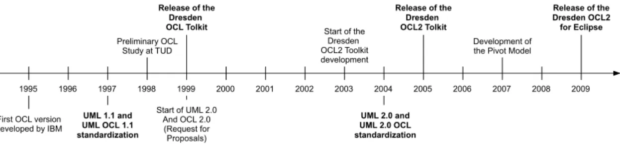
which must be valid before the execution of a method), postconditions (conditions which must be valid after the execution of a method) and invariants (conditions which must be valid during the lifetime of an UML object). As mentioned above, OCL has been designed as an extension of the UML. But today, OCL is also used to define constraints on other modeling languages and DSLs. The first version of OCL was developed by IBM around 1995 [PDD+09]. In 1997, OCL became part of theUnified Modeling Language (UML)and was released as anObject Management Group
(OMG)specification in the version 1.1 [OMG97, Wik09]. In 1999, the development ofUML 2.0
and OCL 2.0 was started with theUML 2.0 and UML 2.0 OCL Request for Proposals[Wik09]. In September 2004, the 2.0 versions of UML and OCL were released. The OCL 2.0 specification has been published by the OMG and is available at the OMG website [OMG06c]. The OCL 2.1 specification is currently in development. A preview of the 2.1 specification is available at the OMG website [OMG09a]. A general and detailed introduction into OCL has been published by Warmer and Kleppe [WK04].
2.3
THE GENERIC THREE LAYER METADATA ARCHITECTURE
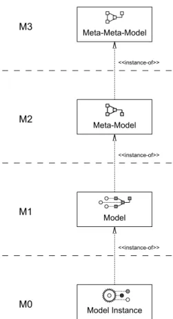
Each modeling language is defined in another language, its meta-modeling language. For exam-ple, the Unified Modeling Language is defined using theMeta Object Facility (MOF)[OMG06b], the standardized meta language of the OMG. The MOF is used to describe the UML model that can be used to model UML models. Generally speaking, each model requires a meta-model that is used to describe the meta-model. The meta-model can be instantiated by meta-model instances (for example a UML class diagram could be instantiated by a UML object diagram). One may also say, that the model is an instance of its meta-model. This model to meta-model instance-of rela-tionship can be considered as relative, because every model is an instance of a meta-model. The meta-model is again an instance of a meta-meta model (the meta-model’s meta-model). Each model can be enriched with OCL constraints that are defined on the model and can then be verified for instances of the model.
The OMG introduced theMOF Four Layer Metadata Architecture[OMG06b][OMG09b, p. 16ff] which is used to arrange and structure the meta-model, the model, and its model instances into a layered hierarchy (see Figure 2.1; the layout of the illustration is oriented at the conceptual framework introduced by Matthias Bräuer [Brä07, p. 28]). Generally, four layers exist, the
Meta-Meta-Model Layer (M3), the Meta-Model Layer (M2), the Model Layer (M1), and the Model
Instance Layer (M0).
OCL constraints can be defined on both meta-models and models to verify models (Model-Level
Constraints) respectively instances (Instance Level Constraints). Thus, the four layer metadata
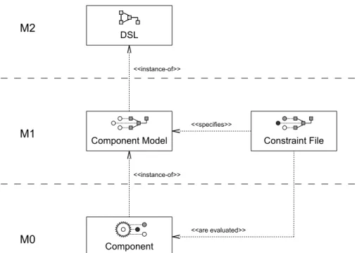
architecture can be generalized to aGeneric Three Layer Metadata Architecturein the scope of an OCL definition (see Figure 2.2) [DW09]. On theMn+1 Layeris the meta-model that is used to define the model that shall be constrained. On theMn Layeris the model that is an instance of the meta-model and can be enriched by the specification of OCL constraints. Finally, on the
Mn-1 Layeris the model instance on that the OCL constraints shall be verified. Please note that
in the context of this generic layer architecture an instance can be both a model (like a UML class diagram) or a model’s instance (e.g., a set of objects like Java run-time objects). This is illustrated in Table 2.1.
Meta-Model Model Model Instance <<instance-of>> <<instance-of>> M2 M1 M0 Meta-Meta-Model <<instance-of>> M3
Figure 2.1: The MOF Four Layer Metadata Architecture.
Meta-Model Model Model Instance <<instance-of>> <<instance-of>> Mn+1 Mn Mn-1
Model-Level Constraints (defined on the Meta-Model
Instance-Level Constraints (defined on the Model)
Mn+1 Meta-Meta Model Meta-Model
Mn Meta-Model Model
Mn-1 Model Instance
Table 2.1: Constraints can be defined on both meta-models and models and thus, evaluated on models (model-level constraints) or instances (instance-level constraints).
.
2.4
TWO WAYS TO VERIFY CONTRACTS AT RUN-TIME
Generally, two different approaches exist to verify contracts at component run-time: the
Inter-pretativeand theGenerative Approach[DW09]. The interpretative approach verifies contracts by
interpreting them on a model and its instances, the generative approach instead generates code or queries that can be executed to verify the contracts. Both approaches are shortly defined in the following.
2.4.1
The Interpretative Approach
The first possible approach for contract verification is theInterpretative Approach. The interpreta-tive approach uses a model and at least one model instance to verify the contract on this instance using an interpreter (see Figure 2.3, part A). The interpretative approach for example can be used to verify that the attributeageof an objectPersonis positive
2.4.2
The Generative Approach
The second possible approach is theGenerative Approach. The generative approach uses a code generator to generate code that can be executed for contract verification (see Figure 2.3, part B). E.g., Java code (that ensures a set of OCL constraints defined on a UML class diagram, during code execution) could be generated. Different techniques like Aspect-Oriented Programming
(AOP)or JavaAssertions[GJSB05, p. 373ff] could be used.
2.5
DRESDEN OCL
The Dresden OCL Toolkit has been developed at the Technische Universität Dresden (TUD) since 1998. It provides a collection of tools that can be used by other case tool developers to integrate them into their software. E.g., theOCL2 Parserof the toolkit can be integrated into aUML Case Toolto enrich UML diagrams with OCL constraints. Today, the toolkit is one of the major software projects at the software technology group and three different versions of the toolkit have already been released. Figure 2.4 shows a time line illustrating the different releases of OCL and the Dresden OCL Toolkit.
M
eta
-M
o
de
l
M
o
de
l
M
o
d
el
In
sta
n
ce
< < in sta nc e-of > > < < in sta nc e-of > >C
o
ns
tra
in
ts
< < re fin es > > < < ru ns -o n> > Mn+1 Mn Mn-1C
od
e
< < ar e-tra ns fo rm ed -in to > >M
e
ta
-M
od
el
M
o
d
el
M
od
e
l In
sta
n
ce
< < in sta nc e-of > > < < in sta nc e-of > >C
o
n
st
ra
in
ts
< < re fin es > > < < ar e-in te rp re te d-on > >A
: I
n
te
rpr
et
at
iv
e
A
pp
roa
ch
B
: G
en
er
a
tiv
e
A
p
pr
oa
c
h
M n+ 1 M n M n-1 Figure 2.3: T he tw o dif ferent v erification approac hes. A: Interpret ativ e Approac h, B: Generativ e Approac h.1995 1996 1997 1998 1999 2000 2001 2002 2003 2004 2005 2006 2007 2008 2009
First OCL version developed by IBM UML 1.1 and UML OCL 1.1 standardization Start of UML 2.0 And OCL 2.0 (Request for Proposals) UML 2.0 and UML 2.0 OCL standardization Development of the Pivot Model Start of the Dresden OCL2 Toolkit development Preliminary OCL Study at TUD Release of the Dresden OCL2 Tolkit Release of the Dresden OCL Tolkit Release of the Dresden OCL2 for Eclipse
Figure 2.4: The different releases of OCL and the Dresden OCL Toolkit.
2.5.1
The Dresden OCL Toolkit
A preliminary OCL study at the Technische Universität Dresden was done by Andreas Schmidt [Sch98] in 1998, examining how OCL could be mapped to theStructured Query Language (SQL). The first base for the toolkit was realized by Frank Finger in 1999 [Fin99, Fin00]. An OCL standard library and possibilities to load and parse UML models and OCL constraints and furthermore the possibility to generate Java code from OCL constraints were implemented. The instrumentation of the created Java code was realized by Ralf Wiebicke [Wie00]. This first released version of the toolkit was calledDresden OCL Toolkit (DOT).
2.5.2
The Dresden OCL2 Toolkit
The development of a second version of the toolkit started in 2003. The basis of this version was created with the adaptation of the Dresden OCL Toolkit to theNetbeans Metadata Repository
(Netbeans MDR)by Stefan Ocke [Ock03]. This version of the toolkit was namedDresden OCL2
Toolkit (DOT2). It was based on the OCL standard in the version 2.0 [OMG06c]. The DOT2
provided the loading and parsing of UML models and OCL constraints and the transformation of constrained models into SQL [Hei05, Hei06]. The possibility to generate and instrument Java code for OCL constraints was adapted from the Dresden OCL Toolkit to the Dresden OCL2 Toolkit by Ronny Brandt in 2006 [Bra06].
2.5.3
Dresden OCL2 for Eclipse
Since 2007 the Dresden OCL2 Toolkit has been replaced by a third version. The implementation
of aPivot Model by Matthias Bräuer [Brä07] made the newest version of the toolkit
indepen-dent from specific repositories and it can therefore be adapted to many different meta-models. By now, adaptations to the UML2 meta-model of theEclipse Model Development Tools Project [URL09e] and to theEMF Ecoremeta-model are supported. This newest version of the toolkit is calledDresden OCL2 for Eclipse (DOT4Eclipse)because it is based on theEclipse/OSGi compo-nent model. In addition to the implementation of the pivot model, theOCL2 Parserto load and verify OCL constraints [Thi07], theOCL2 Interpreter[Bra07] and theOCL22Java Code Generator [Wil09] have been reimplemented and integrated into Dresden OCL2 for Eclipse.
The Architecture of Dresden OCL2 for Eclipse
The architecture of Dresden OCL2 for Eclipse is shown in Figure 2.5. The architecture is the result of the work of Matthias Bräuer [Brä07] and can easily be extended. The architecture can be separated into three layers: TheBack-End, theBasisand theTools Layer.
Back-End OCL22Java Pivot Model Meta-Model <<is-adatped-to>> Essential OCL <<extends>> Tools OCL2 Parser <<uses>>
Model Bus <<stores-instances>>
<<uses>>
OCL2 Interpreter <<uses>>
<<uses>> <<uses>>
Basis
Figure 2.5: The architecture of Dresden OCL2 for Eclipse.
Meta-Model Model Model Instance <<instance-of>> <<instance-of>> Constraints <<refines>> <<are-evaluated-on>> Mn+1 Mn Mn-1 Essential OCL <<instance-of>> <<extends>> Pivot Model <<is-a>>
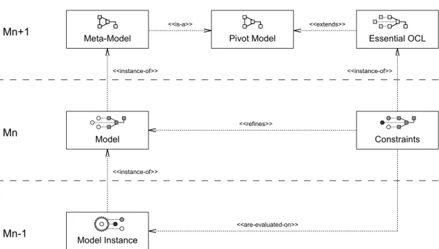
Figure 2.6: The architecture of Dresden OCL2 for Eclipse in respect to the Generic Three Layer Metadata Architecture.
The back-end layer represents the repository and the meta-model that can easily be exchanged because all other packages of the Dresden OCL2 for Eclipse do not directly communicate with the meta-model but use thePivot Modelthat delegates all requests to the meta-model instead. For example, a possible meta-model is the UML2 meta-model of theEclipse Model Development
Tools (Eclipse MDT) Project [URL09e]. The second layer is the toolkit basis layer and contains
thePivot Model, Essential OCLand theModel Bus. The use of the pivot model was explained
before. The packageEssential OCLextends the pivot model to provide meta-model elements for OCL expressions.1 The packageModel Busloads, manages and provides access to models and model instances the user wants to work with. The third layer contains all tools that are provided by the toolkit. This layer contains theOCL2 Parser(which is essential, because the other tools require models that are enriched with already parsed and syntactically and semantically checked constraints), theOCL2 Interpreter, and theOCL22Java Code Generator. All the tools use the packages of the second layer to access models and model instances and to work on OCL constraints.
Dresden OCL2 for Eclipse has been developed as a set of Eclipse/OSGi plug-ins. All packages that are located in the basis and tools layer are implemented as different Eclipse plug-ins. Additionally, Dresden OCL2 for Eclipse contains some plug-ins to provide GUI elements such as wizards and examples to run Dresden OCL2 for Eclipse with some simple models and OCL expressions.
Dresden OCL2 for Eclipse and The Generic Three Layer Metadata Architecture
The architecture of Dresden OCL2 for Eclipse was designed in respect to the Generic Three Layer Metadata Architecture (introduced in Section 2.3, see Figure 2.6). At theMn+1 Layer, different meta-models can be adapted to the toolkit by adapting them to the pivot model. Afterwards, models defined with the elements of these meta-models can be loaded into the toolkit at the
Mn Layer. The models can be enriched with OCL constraints that are described using their own
meta-model Essential OCL, which is described at theMn+1 Layerby extending the pivot model. At theMn-1 Layer model instances of models loaded before can be imported into the toolkit and OCL constraints can be verified on these model instances by using the OCL2 Interpreter or the OCL22Java Code Generator. Please note that model instances inside the toolkit can be both models like UML class diagrams or model instances like Java objects.
2.6
A MOTIVATING EXAMPLE
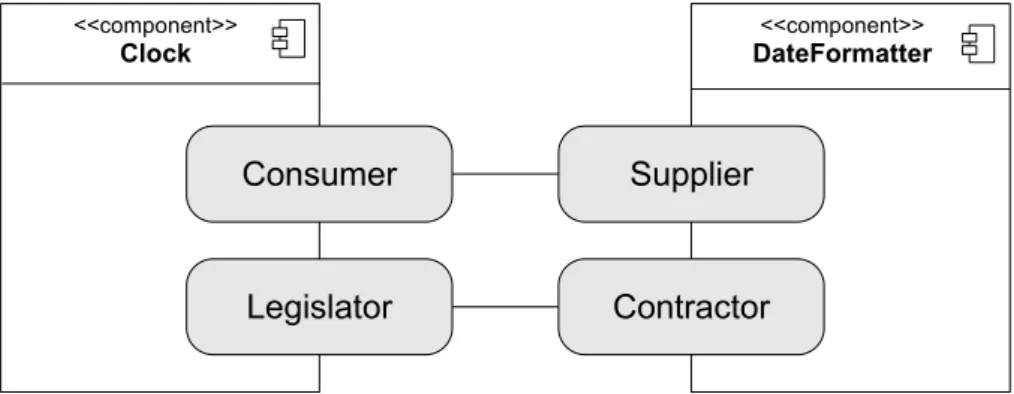
This section will introduce a motivating example for a component interface contract to which this work will refer multiple times. It has been developed by Jens Dietrich [DJ08, Sect. 2] to explain contract-able components. The so-calledClock Exampleis shown in Figure 2.7.
The example contains two components, a Clock and a DateFormatter component. The
Clockcomponent is responsible to display the current time and date on a screen. The com-ponent defines a port calleddateformatterthat can be bound by anyDateFormatter com-ponent that provides a date format mechanism whose results can be displayed by the clock component. This date format mechanism can be a Java interface implementation of the required interfaceClock.dateformatter.class, or an XML-Schema implementation of the required interfaceClock.dateformatter.formatdef. At least one of these two interfaces must be bound by aDateFormattercomponent to provide the required dateformatterservice. At run-time, differentDateFormatterscan be connected to the Clock component (see Figure 2.8) and the user can decide, whichDateFormatterhe wants to use in hisClockview. Listing
1The Essential OCL implementation does not conform completely to the Essential OCL package as specified in the
OCL specification [OMG06c]. Some minor redesigns have been done by Matthias Bräuer, who implemented Essential OCL for the toolkit. A documentation of his Essential OCL implementation can be found in [Brä07, Appendix B].
<<component>>
Clock
dateformatter service-provider <<component>>DateFormatter
class formatdef dateformatterFigure 2.7: A simple Clock Example.
1 public interface DateFormatter {
2
3 String format(java.util.Date date); 4
5 String getName(); 6 }
Listing 2.1: TheDateFormatterinterface.
:Clock
a:DateFormatter
class formatdefb:DateFormatter
c:DateFormatter
Figure 2.8: At run-time, different DateFormatter components can be bound to the Clock compo-nent using different interfaces of the port Clock.dateformatter.
2.1 shows the required interface that must be implemented byDateFormattercomponents that bind the port using theClock.dateformatter.classinterface. The interface declares two methods. The methodgetName()has to return the name of the date format and the method
format(Date)can be used to convertjava.util.Dateobjects into formattedStrings.
Dietrich uses the clock example for component contract definitions of different types that can be verified by the component verification languageTreaty(see also Section 3.1). Such contract defi-nitions can be inheritance relationships between Java interfaces and classes,XML Schemataand XMLfiles, andJUnittests to check functional and non-functional requirements on Java methods. The functional JUnit tests that are provided with the Clock Example test the method format (Date)of the Java DateFormatterinterface. Listing 2.2 shows the functional JUnit tests. These functional tests can also be described using OCL constraints. Listing 2.3 shows the same contract as a set OCL constraints. The first two OCL expressions are definitions that define new functions that are required to verify the following constraints. The functioncontains(String, String)checks if the second givenStringis contained in the first. This method must be de-fined manually because the OCL typeStringdoes not define acontains()method like the
Stringtype in Java. The second methodgetMonth()is used to extract from a givenDate ob-ject the English name of its month. The method is not completely shown in the listing because it contains eleven nestedif-clauses which are not very interesting. The three following constraints check whether or not the result of the methodformat(Date)of everyDateFormatter con-tains the year, the month and the day of the givenDate.
The example OCL contract shows that OCL is a very powerful constraint language that can be used to describe functional constraints on component interfaces. Although the OCL Standard
Librarydoes not provide many operations to reason on the OCL types, more operations can be
defined using definitions to extend the power of OCL.2 During this work, OCL will be used to define contracts on component interfaces such as in the clock example. Because OCL does not support non-functional expressions, only functional constraints will be supported in the OCL con-tracts. The non-functional constraints contained in the clock example (e.g., theformat(Date)’s execution time) will still be expressed using JUnit tests and the JUnit vocabulary of Treaty.
2.7
THE CONSUMER/SUPPLIER ROLE MODEL
As already mentioned in Chapter 1, components interact via required and provided interfaces. Each of such interactions is realized by at least two components, one component having a re-quired interface and one component implementing this interface with a provided interface. This relationship can be described using a simpleRole Model[RG98, Section 3]. The component defin-ing a required interface plays theConsumerrole because it consumes the interface provided by another component and the component providing the interface plays theSupplierrole [DJ08] (See Figure 2.9. The illustration of role models was inspired by the work of Dirk Riehle and Thomas Gross [RG98]). The Consumer/Supplier role model applied to theClock Example (introduced in Section 2.6) is shown in Figure 2.10.
This Consumer/Supplier role model is able to describe a simple connection relationship between components, but no contract definition on such a connection. Szyperski [Szy00] points out that contracts are “most naturally expressed as constraints and conditions overmodelvariables [...] that do not relate to an implementation. [... Implementations] need to establish the mapping between their implementation variables and the abstract model variables.” In addition to that, the role model is extended by two other roles, theLegislator role and theContractorrole. Ev-ery component playing theConsumerrole can also play theLegislatorrole. This means that the component defines a contract specifying the required interface of hisConsumer role in more
2Furthermore, the OCL 2.1 specification–that is currently in development–will contain some additional methods that
will improve the power of the OCL standard library [OMG09a].
1 public class DateFormatterFunctionalTests {
2
3 private DateFormatter formatter = null;
4 private Date testedDate = null;
5
6 public DateFormatterFunctionalTests(DateFormatter formatter) {
7 super();
8 this.formatter = formatter;
9 }
10
11 @Before
12 public void setUp() {
13 testedDate = new GregorianCalendar(1987, 6, 21).getTime();
14 }
15
16 @After
17 public void tearDown() {
18 testedDate = null; 19 formatter = null;
20 }
21
22 @Test
23 // At least the last two digits of the year should be printed.
24 public void test1() {
25 String s = formatter.format(testedDate); 26 assertTrue(s.contains("87"));
27 }
28
29 // The month should be printed either as a number or using its name.
30 @Test
31 public void test2() {
32 String s = formatter.format(testedDate);
33 assertTrue(s.contains("7") || s.contains("July"));
34 }
35
36 // The day should be printed.
37 @Test
38 public void test3() {
39 String s = formatter.format(testedDate); 40 assertTrue(s.contains("21"));
41 }
42 }
Listing 2.2: The functional JUnit tests defined on the DateFormatter interface (the interface Clock.dateformatter.class that can be implemented by Java classes). The code has been taken from the SVN available at the Treaty project’s website [URL09s]. The Java-doc comments have been adapted for graphical reasons.
1 −− A method checking whether or not string2 is a substring of string1.
2 context DateFormatter
3 def:
4 contains(string1: String, string2: String): Boolean = 5 if (string1.size() < string2.size()) then
6 false
7 else
8 Set{1 .. (string1.size() − string2.size())} 9 −> exists(index : Integer | string1
10 .substring(index, index + string2.size()) = string2)
11 endif
12
13 −− A helper method to convert a Date into the English name of its month.
14 context DateFormatter
15 def:
16 getMonth(aDate: Date): String = 17 if (aDate.getMonth() = 0) then 18 ’January’
19 else
20 −− ... 10 following nested if statements ...
21 endif
22
23 −− At least the last two digits of the year should be printed.
24 context DateFormatter::format(aDate: Date): String
25 post containsYear: 26 let
27 year: String = aDate.toString().substring(27, 28)
28 in
29 self.contains(result, year) 30
31 −− The month should be printed either as a number or using its name.
32 context DateFormatter::format(aDate: Date): String
33 post containsMonth: 34 let
35 month1: String = aDate.toString().substring(5, 7) 36 in
37 let
38 month2: String = self.getMonth(aDate)
39 in
40 self.contains(result, month1) or self.contains(result, month2) 41
42 −− The day should be printed.
43 context DateFormatter::format(aDate: Date): String
44 post containsDay: 45 let
46 day: String = aDate.toString().substring(9, 10)
47 in
48 self.contains(result, day)
Listing 2.3: Three OCL constraints defined on the DateFormatter interface Clock.dateformat-ter.class that can be implemented by Java classes. Please note that the constraints are defined using the Java class java.util.Date. Thus, the method substring(..) can be used to convert the Date into strings representing the day, the month, and the year of the date (lines 27, 35, and 46).
Consumer
Supplier
Figure 2.9: The Consumer/Supplier role model.
Consumer
Supplier
<<component>>
Clock DateFormatter<<component>>
Figure 2.10: The Consumer/Supplier role model applied to a Clock and a DateFormatter compo-nent.
Consumer
Supplier
Legislator
Contractor
Figure 2.11: The extended Consumer/Supplier role model.
Consumer
Supplier
Legislator
Contractor
<<component>>
Clock DateFormatter<<component>>
Figure 2.12: The extended Consumer/Supplier role model applied to a Clock and a DateFormatter component.
Client
Server
<<component>>
Client <<component>>Server
<<uses>>
Contractor
Legislator
Consumer
Supplier
<<component>>
Consumer <<component>>Supplier
<<uses>>
Legislator
Contractor
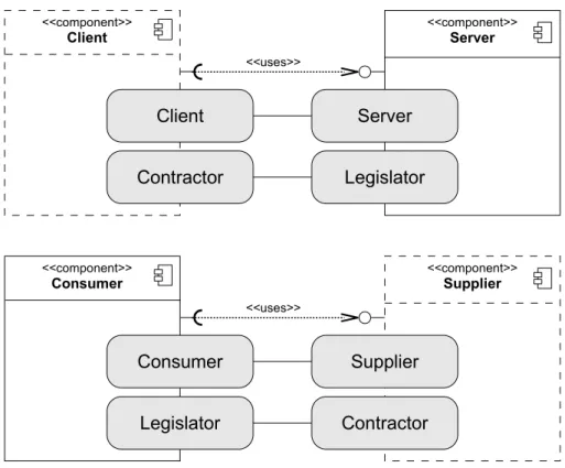
Figure 2.13: The difference between a classical Client/Server and a Consumer/Supplier relation-ship. In a Client/Server relationship the user has to implement a Client that uses a provided service and fulfills a Server’s contract. In a Consumer/Supplier relationship the user has to im-plement a Supplier that provides a required services and fulfills a code Consumer’s contract. The components that must be implemented by users are drawn with dashed lines.
details. Every component that wants to provide an interface required by aConsumerthat is also
aLegislatorhas to fulfill theLegislator’scontract and thus, has also to play the Contractorrole.
The extended Consumer/Supplier role model is shown in Figure 2.11. The extended Consumer/-Supplier role model applied to the Clock/DateFormatter example is shown in Figure 2.12.
One may argue that the Consumer/Supplier role model is similar to theClient/Serverrelationship that–for example–is used by Bertrand Meyer [Mey97, p. 331ff] to describe pre- and postcondi-tions in the context ofDesign by Contract (DBC). But there is a big difference between these two role models! In classical design by contract, the pre- and postconditions are defined on a provided method of theServercomponent that can be invoked by user-definedClients(see Fig-ure 2.13, top). In the Cosumer/Supplier role model the situation is different. TheConsumeruses a service provided by theSupplier, but the contract is defined on the required interface of the
Consumer(see Figure 2.13, bottom). The user must provide an interface that fulfills the given
contract. Instead of calling the provided method, the user has to implement the provided method and its contract. Furthermore, in the Client/Server relationship the same service can be called by multiple clients. In the Consumer/Supplier relationship the same service can be implemented multiple times instead.
The defined contracts on required interfaces must be verified at any time aContractorcomponent binds the required interface of aLegislator component. As mentioned above, components can be loaded, executed and unloaded at run-time. Thus, the contracts of contract-able components must be validated at run-time, when theContractorcomponent is bound to theLegislatoror the
Legislatorinvokes a provided operation of theContractor. If contracts are violated, the contracting
system must decide, if an exception has to be thrown, the user must be informed or the violation should simply be logged.
2.8
ASPECT-ORIENTED PROGRAMMING
Aspect-Oriented Programming (AOP) is a programming paradigm that solves some problems
that cannot be solved by object-oriented programming such asCrosscutting Concerns [AK07]. Crosscutting concerns are “design and implementation problems that cut across several places in [a] program.” [AK07]. They occur in many software systems and their implementation leads
to Code Tangling, Scatteringand Code Replication [AK07]. A typical example for crosscutting
concerns are logging mechanisms that log some run-time events such as the entry of every method. If such a logging mechanism will be implemented manually, every method of every class that shall be logged has to be refactored by adding additional lines for the logging mechanism. If the logging mechanism shall be removed or adapted, every of these methods has to be refactored again. Another typical example for crosscutting concerns are constraint instrumentations into run-time code [Eis06, p. 32].
AOP defines additional code fragments in separate files calledAspects. According to theAspectJ concept, an aspect is a piece of code which [ABR06, AK07]:
1. Specifies one or several points in the control flow of the running program (join points), 2. Specifies sets of join points (pointcuts),
3. Defines what happens if one of the pointcuts is reached; meaning which code will be exe-cuted additionally at these points (advices).
Aspects are always defined in relation to a core, are specified separately from this core and are woven into this core by anAspect Weaver[Aßm03, p. 260]. For the logging example such an aspect must define a pointcut that describes the entry joinpoint of any method that shall be logged. Furthermore, an advice describing the additional logging code that shall be executed before the execution of any of these methods must be provided.
Some languages that realize aspect-oriented programming are AspectJ, AspectC++ and Eos [AK07]. Aspects defined by AspectJ are basically separated into pointcut definitions and advice definitions. A simple AspectJ aspect is shown in Listing 2.4. It describes all public methods of a classSampleClassin its pointcutpublicMethods(SampleClass)(lines 3-5) and a simple advice that is executed before the call of these methods (lines 7-9). AspectJ provides instru-mentation technologies for all constraint types defined in OCL and thus can be used to integrate transformed OCL constraints into Java classes [Wil09, p. 8]. A detailed documentation of As-pectJ is available in the bookAspektorientierte Programmierung mit AspectJ 5from Oliver Böhm [Böh06] and at the AspectJ website [URL09c].
1 public aspect LoggingAspect {
2
3 protected pointcut
4 publicMethods(SampleClass aClass):
5 call(public SampleClass.∗(..)) && this(aClass); 6
7 before(SampleClass aClass) : publicMethods(aClass) {
8 System.out.println("Entered a public method.");
9 }
10 }
2.9
THE ECLIPSE/OSGI COMPONENT MODEL
An example for a successful component model is the universal tool platformEclipse [ABH+06, DJ08]. The first version of Eclipse has been released by IBM in in November 2001 [Dau06, p. 1]. Today, Eclipse provides the de facto standard development environment for Java applications. All components of Eclipse are available at the Eclipse Website [URL09g].
Eclipse is based on a very small core that is responsible for the life cycle management of all other components of Eclipse. The components of Eclipse are calledplug-ins[Dau06, p. 363f]. As well as components, plug-ins have a specific life cycle and can be identified, loaded, exe-cuted and unloaded at run-time [DHG07]. Eclipse plug-ins are plugged together usingExtension
PointsandExtensions(see Figure 2.14). Plug-ins providing extension points can be considered
asConsumers, plug-ins implementing extension points with extensions can be considered as
Suppliers(see also Section 2.7). Each plug-in is organized as a file directory or JAR archive and
can contain an Extensible Markup Language (XML) file called plugin.xml [Dau06, p. 364]. Theplugin.xmldescribes all extension points provided and all extension points extended by the plug-in. For every provided extension point, theplugin.xmlreferences an extended XML schema definition in that the extension point is specified in more details [ABH+06]. Additional settings of the plug-in–like its name, id and optionally its activator class–are defined in the plug-ins
MANIFEST.MFin itsMETA-INFdirectory.
2.9.1
The Extension Point Schema
AnExtension Point Schemaprovides the possibility to define highly polymorphic contracts and
complex logical expressions [DJ08]. The extension point schema architecture is shown in Figure
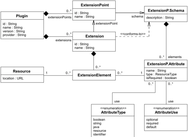
0..* ExtensionP.Schema description : String 1 Resource location : URL Extension id : String name : String ExtensionPoint id : String name : String extensions 0..* extensionPoints Plugin id : String name : String version : String provider : String schema extensionPoint ExtensionP.Attribute name : String type : ResourceType isRequired : boolean 0..* elements ExtensionElement 0..* 0..* 0..* 1 <<conforms-to>> <<enumeration>> AttributeType boolean string java resource identifier <<enumeration>> AttributeUse optional required default use use 0..* 0..*
Figure 2.14: The Eclipse/OSGi component model.
2.14. Via its ExtensionPointSchema, an ExtensionPointdefines a set of Extension-PointAttributesthat must be provided by any component extending theExtensionPoint
with anExtension. An example extension point schema using the clock example is shown in Listing 2.5. Each extension point schema has the same name as the corresponding extension point’s id followed by .exsd. Each schema must define a root node named <extension>
containing the three attributes point, id and name to define an extension belonging to the defined extension point [Dau07, p. 42]. Inside the root element<extension>more attributes can be defined to specify the extension in more details. Attributes can be nested using the special elements<sequence>and<choice>that can be altered by defining multiplicities [Dau07, p. 42].
Defined attributes can be of the typesStringandBoolean. Stringtypes can be altered by adding anAttribute Kindof the typeJava,Resource, orIdentifier[Dau07, p. 42]. String
attributes of the kindJavareference Java classes and interfaces that must be provided by the ex-tension. ForJavaattributes abstract classes or interfaces can be defined that must be extended and implemented to extend the extension point. Resource attributes can be used to adress every type of file that is located in the plug-in’s directory or a sub directory (e.g., class files, source code, images and property files). The attributes of an extension point schema can be set asrequired
or optional and can provide a default value [Dau07, p. 42]. Furthermore, attributes can bedepricatedortranslatableto be configured in a property file for different languages. Each element and attribute can be described using a<documentation>field in the schema file [Dau07, p. 42].
The extension point schema shown in Listing 2.5 defines an extension point callednet.java .treaty.eclipse.example.clock.dateformatterthat contains an element service-Providerthat can be configured by an attributeclassproviding a Java file to implement the date formatter or by an attributeformatdef providing an XML resource describing the date format of the extended date formatter (this extension point is used to define thedateformatter
extension point of the motivating example presented in Section 2.6).
2.9.2
The Plug-in.xml File
Whenever an extension extends a defined extension point, the extension must be defined ac-cording to the extension point schema [ABH+06]. Listing 2.6 shows a plugin.xml file that extends the clock example’s extension point. It defines the<extension>element and provides the required attributesid,nameandpoint. Furthermore, it defines the<serviceprovider>
element and defines a class that provides the date formatter service of this extension.
Figure 2.15 shows the relationship between theplugin.xmlfile and the extension point schema according to Aßmann et al. [ABH+06, p. 163]. Eclipse controls whether or not the specification of the extension point is fulfilled. By using XML to define extension points, “[...] the plugin description is machine-processable and can be used to check whether technical constraints are met, both of static and dynamic nature [ABH+06].”
The extension point schema enables the user to define simple contracts like interface or subclass relationships and thus, can be considered as an implementation of theLegislator/Contractor Role
Model(introduced in Section 2.7). But extension point schemata do not support the complete
set of expressions provided by the Object Constraint Language nor non-functional (e.g.,Quality
1 <?xml version=’1.0’ encoding=’UTF−8’?>
2 <schema targetNamespace="net.java.treaty.eclipse.example
3 .clock"> 4 <annotation> 5 <appInfo>
6 <meta.schema plugin="net.java.treaty.eclipse.example
7 .clock" id="net.java.treaty.eclipse.example
8 .clock.dateformatter" name="dateformatter"/> 9 </appInfo>
10 <documentation>
11 An extension point to provide a date formatter for 12 this clock plug−in.
13 </documentation> 14 </annotation> 15
16 <element name="extension"> 17 <complexType>
18 <attribute name="point" type="string"
19 use="required" />
20 <attribute name="id" type="string" /> 21 <attribute name="name" type="string"> 22 <annotation>
23 <appInfo>
24 <meta.attribute translatable="true"/> 25 </appInfo> 26 </annotation> 27 </attribute> 28 </complexType> 29 </element> 30
31 <element name="serviceprovider"> 32 <complexType>
33 <attribute name="class" type="string"> 34 <annotation>
35 <appInfo>
36 <meta.attribute kind="java"/> 37 </appInfo>
38 </annotation> 39 </attribute>
40 <attribute name="formatdef" type="string"> 41 <annotation>
42 <appInfo>
43 <meta.attribute kind="resource"/> 44 </appInfo> 45 </annotation> 46 </attribute> 47 </complexType> 48 </element> 49 </schema>
Listing 2.5: An extension point schema file for the clock example (Taken from the SVN available at the Treaty project’s website [URL09s]).
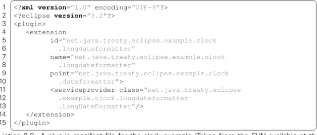
1 <?xml version="1.0" encoding="UTF−8"?> 2 <?eclipse version="3.2"?> 3 <plugin> 4 <extension 5 id="net.java.treaty.eclipse.example.clock 6 .longdateformatter" 7 name="net.java.treaty.eclipse.example.clock 8 .longdateformatter" 9 point="net.java.treaty.eclipse.example.clock 10 .dateformatter">
11 <serviceprovider class="net.java.treaty.eclipse
12 .example.clock.longdateformatter
13 .LongDateFormatter"/> 14 </extension>
15 </plugin>
Listing 2.6: A plug-in manifest file for the clock example (Taken from the SVN available at the Treaty project’s website [URL09s]). The required Java interface DateFormatter is implemented by the class LongDateFormatter (line 11ff).
<schema ...>
<element name=“plugin“> …
</element>
<element name=“extension-point“> <attribute name=“id“ type=“string“ /> <attribute name=“name“ type=“string“ /> <attribute name=“schema“ type=“string“ /> </element> </schema> plugin.xsd <schema ...> ... <element name="serviceprovider"> <complexType>
<attribute name="class" type="string"> <annotation> <appInfo> <meta.attribute kind="java"/> </appInfo> </annotation> </attribute> … </complexType> </element> </schema> plugin.xsd <plugin> <extension-point id="net.java.treaty.eclipse.example.clock .dateformatter" name="dateformatter" schema="schema/net.java.treaty.eclipse .example.clock.dateformatter.exsd" /> </plugin> plugin.xml (consumer) <plugin> <extension id="net.java.treaty.eclipse.example.clock .longdateformatter" name="net.java.treaty.eclipse.example.clock .longdateformatter" point="net.java.treaty.eclipse.example.clock .dateformatter"> <serviceprovider class="net.java.treaty .eclipse.example.clock.longdateformatter .LongDateFormatter"/> </extension> </plugin> plugin.xml (supplier) <extension id="net.java.treaty.eclipse.example.clock .longdateformatter" name="net.java.treaty.eclipse.example.clock .longdateformatter" point="net.java.treaty.eclipse.example.clock .dateformatter"> <serviceprovider class="net.java.treaty .eclipse.example.clock.longdateformatter .LongDateFormatter"/> </extension> <<instance-of>> <<instance-of>> <<instance-of>> <extension-point id="net.java.treaty.eclipse.example.clock .dateformatter" name="dateformatter" schema="schema/net.java.treaty.eclipse .example.clock.dateformatter.exsd" /> <<refers-to>> <<extends>>
Figure 2.15: The relationship between the plug-in.xml files and their schema definitions (according to Aßmann et al. [ABH+06, p. 163]).
2.10
ECLIPSE EQUINOX ASPECTS
TheEclipse/OSGicomponent model has been introduced above (see Section 2.9). The OSGi
im-plementation of Eclipse is calledEquinox[LS08]. Equinox defines a dynamic component language that provides the possibility to load components as late as possible. The separate components (calledBundlesorPlug-ins) can be developed and tested in isolation (regarding their dependen-cies) [SG08].
2.10.1
The Equinox Architecture
Equinox realizes the three OSGi framework layers that are the Module Layer, the Life Cycle
Layer, and theService Layer[LS08]. The Module Layer defines the module/bundle concept and
manages the dependencies between bundles. The Life Cycle Manager manages the bundles’ life cycle and supports installation, update and deinstallation of bundles at component run-time. The Service Layer implements services for a service-based bundle interaction in theJava Virtual
Machine (JVM).
The three framework layers are connected to the Eclipse platform via theFramework Adapter API[LS08]. Since the release of Eclipse 3.2 the standard implementation of this adapter contains points of variability, so-calledHooks[Aßm03, p. 109] to extend the adapter services. Such hooks can be AdapterHooks to adapt methods of the adapter, or BundleWatchers that observe the bundle life cycle. Another important hook is theClassLoadingHookthat can be used to modify the class loading process [LS08].
2.10.2
The Equinox Aspects Project
To extend the Equinox architecture with run-time verification, the bundle load and class load mechanisms could be extended with constraint check code. Constraint integration can be con-sidered as aCrosscutting Concern because often the same constraint has to be evaluated on different interfaces of different components. A well-known technique for crosscutting concerns
isAspect-Oriented Programming (AOP)[ILB+08, p. 26] (see also Section 2.8).
TheEclipse Equinox Aspects Project tries to combine OSGi and AOP [URL09i]. The project
ex-tends the Equinox architecture by adapting theFramwork Adapterto support so-calledLoad-Time
Aspect-Weaving[LS08]. Load-time aspect-weaving weaves the aspects into the classes not at
compile time but at run-time, when the classes are loaded by the class loader [SG08]. Via a
Class-loadingHookthe Java byte code is modified, before the classes are loaded into the JVM’s run-time
environment. Additionally, aBundleFileWrapperFactoryHookmodifies the bundles’ manifest files to register bundle dependencies that may have occured [LS08].
To weave aspects into Eclipse bundles, the aspects files are defined in a new bundle, containing anaop.xmlfile in its META_INFdirectory adressing all aspects that shall be woven into other bundles. Additionally, the packages where these aspects are located must be exported in the
MANIFEST.MFfile. There are two different ways to declare into which bundles the aspects shall be woven at run-time. In theMANIFEST.MFof the aspect bundle, all bundles can be declared, into that the aspects shall be woven using theEclipse-SupplementBundlefield. Alternatively, in a bundlesMANIFEST.MFfile all aspect bundles can be declared that shall be woven into this bundle using theEclipse-SupplementImporterfield. In both fields bundles are described by theirid, wildcards like*can be used to describe sets of bundles [SG08].
The Eclipse Equinox Aspects Project seems to provide a good solution to weave contract check code even into plug-ins that have been developed by third parties and for which no source code is available.
3
RUN-TIME VERIFICATION
APPROACHES
[...] everything is a model. Requirements are models, designs are models, imple-mentations are models and even the description of the system at run-time could be a model as well.
Christian Hein et al. [HRW07]
This chapter presents other works and projects that are related to the topic of this thesis. Some projects realizing run-time verification on component models and some projects focusing on simi-lar tasks are discussed. Furthermore, some requirements and considerations of different projects are presented.
3.1
TREATY
Treatyis a platform-independent component contract language that has been developed by the
team of Jens Dietrich at the School of Engineering and Advanced Technology (SEAT) at the Turitea (Palmerston North) Campus of Massey University, New Zealand [DHG07, DJ08]. The project and further information can be found at the project’s website [URL09s].
Treaty can be used to define contracts between components providing and consuming services. Such contracts are based on a modular and extensible vocabulary and are precise enough to be verified at component run-time using an interpretative verification mechanism (see Subsec-tion 2.4.1). Treaty is largely independent of the underlying component model. A prototypical implementation of Treaty based on the Eclipse/OSGi component architecture is available at the project’s website [URL09s]. The prototype supports contract definitions using different resource types. By now, supported resource types are Java classes and interfaces, XML documents and XML Schema definitions. Furthermore, modified JUnit test cases are supported to define con-tracts on semantic and quality of service aspects.