Turbo Pascal
Graphix Toolbox®
Owner~s
Handbook
BORLAND INTERNATIONAL, INC. 4585 SCOTTS VALLEY DRIVE SCOTTS VALLEY, CALIFORNIA 95066
Copyright © 1987
All Rights Reserved, First Printing, 1987 Printed in U.S.A.
Table of Contents
Introduction ... 1
What Can You Do With the Graphix Toolbox? ... 1
Structure of This Manual ... ; ... 4
Typography ... 5
The Distribution Disk ... 5
Acknowledgments ... 6
CHAPTER 1: A Computer Graphics Primer ... 7
Pixels ... 7
Screens ... 8
Characters and Fonts ... : ... 9
Coordinate Systems ... 9
Absolute Screen Coordinate System ... 10
World Coordinate System ... 10
Windows ... 10
Clipping ... 11
How to Use the Turbo Pascal Graphix Toolbox With Your Hardware ... 12
The IBM PC and True Compatibles ... 13
IBM Color Graphics Card ... 14
Hercules Monochrome Graphics Card ... 14
IBM Enhanced Graphics Adapter ... 15
IBM 3270 PC ... 15
CHAP'fER 2: Getting Started ... 17
Linking Turbo Pascal Graphix Routines into Your Program ... 17
8087 or Non-8087 Installation ... 19
Drawing Points ... 19
Drawing a Single Point ... 20
Drawing a Cluster of Points ... 20
Drawing Points Using a World Coordinate System ... 21
Erasing a Point ... 22
Summary of Point Routines ... 22
Drawing Lines ... 23
Drawing a Single 'Line ... 23
Drawing a "Walking Line" ... 24
Summary of Line-Drawing Routines ... 25
Drawing Squares ... 25
Summary of Square-Drawing Routines ... 26
Drawing Circles ... 26
Summary of Related Routines ... 28
Text ... 28
Displaying Machine-Dependent Text ... 28
Displaying 4x6-Pixel Text ... 30
Summary of Text-Drawing Routines ... 31
Windows ... 31
Defining a Window ... ; ... 32
Displaying a Drawing in a Window ... ~ ... 34
Moving Windows ... 36
Another Use for Windows: the Flow Chart ... 39
Summary of Window Routines ... 43
Pie and Bar Charts ... 44
Pie Charts ... 44
Bar Charts ... 47
Summary of Pie and Bar Chart Routines ... 52
Plotting Curves ... 52
A Simple Example: Plotting a Sine Curve ... 52
The Draw Axis Procedure ... 54
Drawing a Sine Curve with Axes ... 56
Polygon Modification Routines ... 58
Finding a World to Fit a Polygon ... 61
Solving Curve-Fitting Problems ... 63
Fitting a Curve with the Spline Procedure ... 64
Modeling a Curve with the Bezier Procedure ... 66
Summary of Polygon/Curve Routines ... 70
Screens ... 70
Saving and Loading Screens ... 71
CHAPTER 3: Technical Reference ... 79
Turbo Pascal Graphix Files ... 79
Basic System Units ... 80
Supplemental System Units ... 80
High-Level Command Unit ... 80
A Sample Turbo Pascal Graphix Toolbox Program ... 81
Constant and Type Definitions ... 82
AspectFactor [GDRIVER.PAS] ... 82
BackgroundArray [GDRIVERPAS] ... 83
CharFile [GDRIVER.PAS] ... 83
HardwareGrafBase [GDRIVERPAS] ... 83
HeaderSizeGlb [GDRIVER.PAS] ... 83
IVStepGlb [GDRIVER.PAS] ... 84
MaxBackground [GDRIVER.PAS] ... 84
MaxForeground [GDRIVERPAS] ... 84
MaxPiesGlb [GDRIVERPAS] ... 85
MaxPlotGlb [GDRIVERPAS] ... 85
MaxWindowsGlb [GDRIVERPAS] ... 85 .
MaxWorldsGlb [GDRIVERPAS] ... ; ... 85
MinBackground [GDRIVERPAS] ... 86
MinForeground [GDRIVER.PAS] ... 86
PieArray [GDRIVER.PAS] ... 86
PlotArray [GDRIVER.PAS] ... 87
RamScreenGlb [GDRIVERPAS] ... 87
ScreenSizeGlb [GDRIVERPAS] ... 88
StringSizeGlb [GDRIVERPAS] ... 88
WrkString [GDRIVERPAS] ... 88
XMaxGlb [GDRIVER.PAS] ... 89
XScreenMaxGlb [GDRIVER.PAS] ... 89
YMaxGlb [GDRIVER.PAS] ... 89
Quick Reference Guide to Turbo Pascal Graphix Routines ... 90
Procedures and Functions ... 93
BaseAddress [GDRIVERPAS] ... 94
Bezier [GSHELL.PAS] ... 95
ClearScreen [GDRIVERPAS] ... 99
ClearWindowStack [GWINDOW.PAS] ... 100
Clip [GKERNEL.PAS] ... :.101
Clipping [GKERNEL.PAS] ... 102
CopyScreen [GDRIVERPAS] ... 103
CopyWindow [GWINDOW.PAS] ... 104
DC [GDRIVER.PAS] ... 105
DefineHeader [GKERNEL.PAS] ... 106
DefineTextWindow [GKERNEL.PAS] ... 107
DefineWindow [GKERNEL.PAS] ... 109
DefineWorld [GKERNEL.PAS] ... 110
DP [GDRIVER.PAS] ... 111
DrawAscii [GKERNEL.PAS] .1 •••••••••••••••••••••••••••••••••••••••••••••••••••••••••••••••••••••••••••••• 112 DrawAxis [GSHELL.PAS] ... 113
DrawBorder [GKERNEL.PAS] ... 115
DrawCartPie [GSHELL.PAS] ... 116
DrawCircle [GKERNEL.PAS] ... 118
DrawCircleDirect [GKERNEL.PAS] ... 119
DrawCircleSegment [GSHELL.PAS] ... 120
DrawCross [GKERNEL.PAS] ... 122
DrawCrossDiag [GKERNEL.PAS] ... 123
DrawDiamond [GKERNEL.PAS] ... 124
DrawHistogram [GSHELL.PAS] ... 125
DrawLine [GKERNEL.PAS] ... 127
DrawLineClipped [GKERNEL.PAS] ... 128
DrawPoint [GKERNEL.PAS] ... 129
DrawPolarPie [GSHELL.PAS] ... 130
DrawPolygon [GSHELL.PAS] ... 132
DrawSquare [GKERNEL.PAS] ... 134
DrawSquareC [GKERNEL.PAS] ... 135
DrawStar [GKERNEL.PAS] ... 136
DrawStraight [GDRIVERPAS] ... 137
DrawText [GKERNEL.PAS] ... 138
DrawTextW [GKERNEL.PAS] ... 139
DrawWye [GKERNEL.PAS] ... 140
EnterGraphic [GDRIVERPAS] ... 141
Error [GKERNEL.PAS] ... 142
FindWorld [GSHELL.PAS] ... 143
GetAspect [GKERNEL.PAS] ... 144
GetColor [GKERNEL.PAS] ... 145
GetErrorCode [GKERNEL.PAS] ... 146
GetLineStyle [GKERNEL.PAS] ... 147
GetScreen [GKERNEL.PAS] ... 148
GetScreenAspect [GKERNEL.PAS] ... 149
GetVStep [GKERNEL.PAS] ... 150
GetWindow [GKERNEL.PAS] ... 151
GotoXY [GKERNEL.PAS] ... 152
HardCopy [GKERNEL.PAS] ... 153
HardwarePresent [GDRIVERPAS] ... 154
Hatch [GSHELL.PAS] ... 155
InitGraphic [GKERNEL.PAS] ... 156
InvertWindow [GWINDOW.PAS] ... 158
LeaveGraphic [GDRIVERPAS] ... 159
LoadScreen [GDRIVER.PAS] ... 160
LoadWindow [GWINDOW.PAS] ... 161
LoadWindowStack [GWINDOW.PAS] ... 162
MoveHor [GWINDOW.PAS] ... 163
MoveVer [GWINDOW.PAS] ... 164
PD [GDRIVER.PAS] ... 165
PointDrawn [GKERNEL.PAS] ... 166
RedefineWindow [GKERNEL.PAS] ... 167
RemoveHeader [GKERNEL.PAS] ... : ... 168
ResetWindows [GKERNEL.PAS] ... 169
ResetWindowStack [GWINDOW.PAS] ... 170
ResetWorlds [GKERNEL.PAS] ... 171
RestoreWindow [GWINDOW.PAS] ... 172
RotatePolygon [GSHELL.PAS] ... 173
RotatePolygonAbout [GSHELL.PAS] ... 174
SaveScreen [GDRIVER.PAS] ... , ... 175
SaveWindow [GWINDOW.PAS] ... 176
SaveWindowStack [GWINDOW.PAS] ... 177
ScalePolygon [GSHELL.PAS] ... 178
SelectScreen [GKERNEL.PAS] ... 179
SelectWindow [GKERNEL.PAS] ... 180
SelectWorld [GKERNEL.PAS] ... 181
SetAspect [GKERNEL.PAS] ... 182
SetBackground [GDRIVERPAS] ... 183
SetBackground8 [GDRIVERPAS] ... 184
SetBackgroundColor [GDRIVERPAS] ... 185
SetBreakOff [GKERNEL.PAS] ... 186
SetBreakOn [GKERNEL.PAS] ... 187
SetClippingOff [GKERNEL.PAS] ... 188
SetClippingOn [GKERNEL.PAS] ... 189
SetColorBlack [GKERNEL.PAS] ... 190
SetColorWhite [GKERNEL.PAS] ... 191
SetForegroundColor [GDRIVERPAS] ... 192
SetHeaderOff [GKERNEL.PAS] ... 193
SetHeaderOn [GKERNEL.PAS] ... : ... 194
SetHeaderToBottom [GKERNEL.PAS] ... 195
SetHeaderToTop [GKERNEL.PAS] ... 196
SetLineStyle [GKERNEL.PAS] ... 197
SetMessageOff [GKERNEL.PAS] ... 198
SetMessageOn [GKERNEL.PAS] ... 199
SetScreenAspect [GKERNEL.PAS] ... 200
SetVStep [GKERNEL.PAS] ... 201
SetWindowModeOff [GKERNEL.PAS] ... 202
SetWindowModeOn [GKERNEL.PAS] ... 203
Spline [GSHELL.PAS] ... 204
StoreWindow [GWINDOW.PAS] ... 206
SwapScreen [GDRIVERPAS] ... 207
TextDown [GKERNEL.PAS] ... 208
TextLeft [GKERNEL.PAS] ... 209
TextRight [GKERNEL.PAS] ... 210
TextUp [GKERNEL.PAS] ... 211
TranslatePolygon [GSHELL.PAS] ... 212
WindowMode [GKERNEL.PAS] ... 213
WindowSize [GWINDOW.PAS] ... 214
WindowX [GKERNEL.PAS] ... 215
WindowY [GKERNEL.PAS] ... 216
APPENDIX A: Hardware Configurations and Compatibility Problems .... 217
The IBM Color Graphics Card ... 217
Color ... 218
Text ... 219
The Hercules Monochrome Graphics Card ... 219
Color ... 220
Text ... 220
Special Notes ... 221
Compatibility Issues ... 221
Screen Size ... 221
Text Placement ... 222
Color ... 224
Speed ... 225
Premature Termination ... 225
Introduction
Welcome to the Turbo Pascal Graphix Toolbox. The procedures and functions that make up this software package will expand your repertoire of Turbo Pascal pro-gramming tools. With the aid of the Graphix Toolbox, you can develop high-resolu-tion monochrome graphics for IBM PC and PC-compatible computers (using either an IBM CGA, EGA or 3270, AT&T 6300, or a Hercules graphics card).
This manual makes extensive use of Turbo Pascal programming examples; a good working knowledge of Turbo Pascal is assumed. If you need to brush up on your Pascal knowledge, refer to the Tllrbo Pascal manual, and/or the Turbo Pascal Tutor .
. What Can You
Do
With the Graphix Toolbox?
The Turbo Pascal Graphix Toolbox is a versatile package, designed for both simple and complicated graphics applications. Simple procedures allow you to draw
• Points
• Lines
• Rectangles with optional shading
• Ellipses
High-level procedures let you create the more complex graphics that are often needed in business and scientific applications:
• Labeled pie charts
• Bar charts with programmable shading
• A variety of curves, using different linestyles and with optional smoothing
• Curve fitting
• Line and solid modeling
• Labeled coordinate axes
• Polygons of any shape, with optional rotation or translation
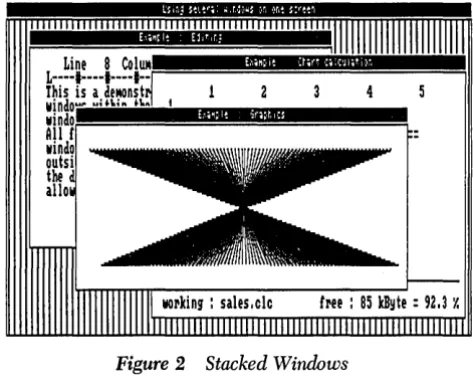
All your drawings can be displayed either on the full screen, or in windows that you define. You can also draw on a RAM (virtual) screen in memory, without display, and move the resulting images to the displayed screen when desired.
Here are some examples of the kind of drawings you'll soon be able to generate with the Graphix Toolbox.
' ... , .. ,',' "" ,',',.:'" ,':: ',' . ' I ' I .
, ,
( , ' . I • ~ • • • ' :
. ","'.: I'. ':',' :" .. "
Introduction
Line 8 CoIUM
L----I----I----I--r==============;u
This is a deMOnst
windo'''' .. a,,; .. ~,,~ t
lIindo;:;================;
All
r
lIindo
[image:12.507.134.386.37.603.2] [image:12.507.148.385.51.242.2]autsi the alla
Figure 2 Stacked Windows
JAN
I30.35
Figure 3 Variations on a Pie Chart
0
lhe emple function
~
\
~' US,6 !D, o ,0 o.sO
'0000°
0,1! US
OJ! 0,11 0,5) US 0.76 o.s$ 1.00 ·],IH7H 1.00 ·l,1\ 1,,1' I' '1'1"1,1" "I'
,,,,'
H, "I." [image:13.507.110.365.52.227.2]·UI ·US ·O,\l O,IS US 2.21
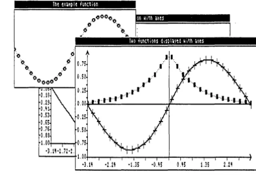
Figure 4 Two Curves Displayed with Coordinate Axes
Structure
of
This
Manual
This manual is divided into five parts:
• Chapter 1 provides an overview of the Turbo Pascal Graphix Toolbox. Basic graphics terms you need to know in order to use the toolbox are defined, and illustrations of some of the things you can draw are given. This chapter also talks about the different hardware configurations that can run the Turbo Pas-cal Graphix Toolbox.
• Chapter 2 gets you started on using the Turbo Pascal Graphix Toolbox. Turbo Pascal examples for the most commonly used procedures are given, along with the resulting drawings. You'll also see how to define and manipulate windows, and save and print the graphic images you create.
• Chapter 3 is the technical reference part of the manual. All the constants, types, procedures, and functions contained in the Turbo Pascal Graphix Tool-box are described, in alphabetical order, with parameters, function, restric-tions, and examples.
• Appendix A explains how to use the Turbo Pascal Graphix Toolbox with differ-ent hardware configurations.
Typography
The body of this manual is printed in normal typeface. Special characters are used for the following special purposes:
Alternate Alternate characters are used in program examples and procedure and function declarations.
Italics Italics are used to emphasize certain concepts and termioology, such as
predefined standard identifiers, parameters, and other syntax elements. Boldface Boldface type is used to mark reserved words, in the text as well as
in program examples.
Refer to the Turbo Pascal Reference Manual for a complete description of the syntax, special characters, and overall appearance of the Turbo Pascal language.
The Distribution Disk
The Turbo Pascal Graphix Toolbox distribution disk contains the following:
• Installation and demonstration files
• Files containing all the procedures and functions
• All the commented program examples used in Chapter 2
The distribution disk is your only source for the Turbo Pascal Graphix Toolbox files. The first thing you should do upon receiving the disk is to complete and mail the License Agreement at the front of this manual. You should then make a copy of the distribution disk. Put the original disk in a safe place, and use only the copy for doing your work. You should never use the distribution disk for your work, since there is a charge for a replacement copy.
After you complete the License agreement and make a backup copy of the disk, read the README.COM file on the disk. Simply type README from the DOS prompt, and the file will appear. It contains a list of files on the disk, as well as any corrections, comments, or updates on the program.
· Acknowledgments
In this manual, references are, made to several products:
• Flight Simulator is a registered trademark of Sublogic Inc.
• Hercules is a registered trademark of Hercules Computer Technology, Inc.
• IBM is a registered trademark of International Business Machines Inc.
• MS-DOS is a registered trademark of Microsoft Inc.
c
H A p T E R1
A
Computer Graphics Primer
Before you do any drawing with the Turbo Pascal Graphix Toolbox, you will need to understand the graphics and screen display terms used throughout this manual. Each of these concepts is described here, followed by a list of the Turbo Pascal Graphix procedures and functions that apply to each.
Pixels
The term pixel is an acronym for picture element. Pixels, in fact, are the basic elements that make up a video display image. The tiny dots that combine to make the text and graphic images you see on your computer monitor are pixels.
The Turbo Pascal Graphix Toolbox allows you to display pixels as black or white with monochrome cards, or in any color supported by a color card.
Screens
A screen is the configuration of pixels that make up displayed text or graphic images. Depending on the type of graphics card installed in your system, the screen display will be made up of the following horizontal-by-vertical pixel dimen-sions:
• IBM eGA 640x200
• Hercules 720x350
• AT &T 6300 640x400
• IBM 3270 720x350
• IBM EGA 640x350
Because the Hercules display is made up of a greater number of pixels, the graphic images created are finer in grain - that is, they are higher in resolution. Because of their higher resolution, they also take longer to draw. IBM eGA graphics images are coarser grained, and therefore lower in resolution. The concept of resolution is easy to understand if you think of drawings made with pencils or pens; a drawing done with a fine-point drawing pen will be of a higher resolution, and will take longer to draw than one done with a blunt pencil.
For standard text display - that is, the text normally displayed by your system - a screen can also be thought of as a sequence of 80 vertical character columns that make up the width, and 25 lines of characters that make up the height.
There are two types of screens that you can use for creating images with the Toolbox: the screen displayed on your monitor, and a RAM (virtual) screen in memory. You can draw on either screen, but only the monitor screen is viewable; the RAM screen is invisible. The screen you are currently drawing on is called the
active screen. RAM screens are useful for storing complicated images that are used
often and are time consuming to redraw, or for animation, when it would be dis-tracting to allow the computer to visibly redraw the screen.
The procedures and functions that are used to manipulate screens are
elearScreen LoadScreen
eopyScreen SaveScreen
GetScreen SelectScreen
Characters and Fonts
A character is a letter, number, or symbol that is represented on your screen by a rectangular configuration of pixels. A sequence of characters makes up a display of text.
There are two styles - or fonts - in which text can be displayed with the Turbo Pascal Graphix Toolbox:
• A simple, 4x6-pixel upper- and lower-case font that is used to display window headers, pie chart labels, or any text you wish to display in integer multiples of 4x6 pixels
• A larger, higher quality font (8x8 pixels with an' IBM CGA, or the 3270, and the AT&T 6300, and 9x14 pixels with the IBM EGA, or the 3270, and the Her-cules monochrome card) that corresponds to the font normally used with the particular graphics card installed in your system
Exactly how the Turbo Pascal Graphix Toolbox utilizes these two fonts will become clear when you read the next section about coordinate systems.
The procedures and functions that affect text are
DC
DefineHeader
DefineTextWindow
DisplayChar
DrawAscii
DrawText
DrawTextW
TextDown
TextLeft
TextRight
TextUp
Coordinate Systems
A coordinate system is a method used to identify a location according to its position relative to horizontal and vertical axes. In mathematics, usually, and in Turbo Pas-cal Graphix Toolbox programming in particular, the horizontal axis is labeled X, . and the vertical axis Y. The exact location of, for example, a point, is determined by the X and Y coordinates of that point - that is, its distance from the X and Y zero axes.
Coordinate systems are extremely important in graphics programming, since all screen positions for text and graphics must be specified using X and Y coordinates. There are two types of coordinate systems that you can choose when working with the Turbo Pascal Graphix Toolbox: absolute screen and world coordinate systems.
Absolute Screen Coordinate System
The absolute screen coordinate system refers to the entire monitor screen, and the actual character and pixel screen positions, for plotting text and graphics; coordi-nates [0,0] are in the upper left corner of the screen, with the X coordicoordi-nates increasing to the right, and the Y coordinates increasing downward. As mentioned earlier, the screen can be regarded either as a configuration of pixels or as a series of 25 lines by 80 columns.
Text is handled in two ways. The simple, 4x6-pixel font used for window headers and footers can be plotted anywhere on the screen, and can be scaled to be any size that is an integer multiple of 4x6 pixels (for example, 8x12). The higher quality font is plotted according to 80x25 text column and line coordinates.
World Coordinate System
For most graphics, the absolute screen coordinate system will not easily translate to the application's numeric values. A world coordinate system is an arbitrary coor-dinate system that you specify to accommodate your particular application. The numbers you use in your world coordinate system can be (and usually are) com-pletely unrelated to pixel coordinates. In Turbo Pascal Craphix Toolbox language, this is called defining a world.
A world coordinate system is usually used to scale images so that they fit correctly into the windows you have defined. After you define the world for a given window, any images you subsequently draw will be automatically, proportionately scaled to fit the window.
The procedures and functions that affect worlds are
Define World
FindWorld
Windows
ResetWorlds
SelectWorld
screen. You can draw borders, incorporate high-quality text, and label your win-dows with headers or footers. The window you are currently drawing in is called the active window.
A window can be specified to be almost any size, from the whole screen to I vertical pixel by 8 horizontal pixels. You define a window area by specifying the X and Y coordinates of its upper left and lower right corners, with Y coordinates measured in I-pixel units and X coordinates measured in 8-pixel units. These coor-dinates are called window definition coorcoor-dinates. In window definition coorcoor-dinates, the point [0,0] refers to the upper left corner of the screen.
Once you're working within a window, you can redefine its world coordinate sys-tem, thereby allowing multiple images to be displayed within one window, each with its own coordinate system. Coordinate axes, along with lettering, can be easily added to any drawing.
A special RAM memory area, the window stack, is set aside for temporary storage of windows. The stack comes in handy when you have several windows that you want to keep but don't want to display all at the same time. The stack is also used for storing windows that would otherwise be erased when another window is moved over them on the screen.
The procedures and functions that affect windows are
ClearWindowStack Redefine Window SetClippingOff
Clip RemoveHeader SetHeaderOn
Clipping ResetWindows SetHeaderOff CopyWindow Reset\VindowStack SetHeaderToTop DefineHeader RestoreWindow SetHeaderToBottom Define Window SaveWindow SetWindowModeOff Define World SaveWindowStack SetWindow ModeOn DrawBorder SelectWindow StoreWindow GetWindow SelectWorld WindowSize InvertWindow SetBackground WindowX LoadWindow SetBackground8 WindowY LoadWindowStack SetClippingOn
Clipping
The Turbo Pascal Craphix Toolbox allows you to "clip" images at window bound-aries if you wish. This feature accomplishes several purposes:
• It relieves you from having to be exact when you're drawing in a window. The Toolbox does the nitty-gritty of keeping your work within window boundaries.
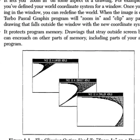
• It lets you "zoom in" on some aspect of a drawing. For example, let's say you've defined your world coordinate system for a window. Once you're work-ing in the window, you can redefine the world. When the image is drawn, the Turbo Pascal Graphix program will "zoom in" and "clip" any part of your drawing that falls outside the window with the new coordinate system.
• It protects program memory. Drawings that stray outside screen boundaries can encroach on other parts of memory, including parts of your application program.
lHISIS A LARGER UDRLD
lHISI;ACDRREcrUDRLD
[image:21.507.86.367.57.338.2]lHE Il A :MALLER UDRLO
Figure 1-1 The Clipping Option Used To "mom In" on a Drawing
There are times when you'll choose not to clip drawings, too. For instance, you may develop a program using the clipping option, but once the program is debugged, and you know your drawings are within bounds, you can turn clipping off. This speeds up the draWing process considerably. Or, if you're working strictly with absolute coordinates, you don't need to worry about drawing outside screen bound-aries.
How to Use the Turbo Pascal Graphix Toolbox
With Your Hardware
There are a few differences between the computer systems and graphics cards that can run the Toolbox. In some cases, these differences require your special consider-ation when creating Toolbox-based programs.
cards. The information below will tell you briefly what you need to know about your particular system; more technical details about certain hardware configura-tions can be found in Appendix A.
The IBM
PCand True Compatibles
The Turbo Pascal Graphix Toolbox runs on any IBM PC, PC Jr., and compatible computer. But what exactly is a true IBM-compatible computer? There are many computers on the market today that are billed as IBM-compatible, and to some extent they are. However, when considering whether a computer is IBM compati-ble, it is important to look at the specific application you are using the computer for. In the case of the Turbo Pascal Graphix Toolbox, you must consider whether the graphics displayed by your computer will be true to your program design.
A potential problem with some IBM compatibles is that their screen display is of a higher resolution than the IBM screen. The Corona PC is a good example. Although the Corona's higher resolution display can make for very high-quality text and graphics, graphic images created with the Turbo Pascal Graphix Toolbox will not display true-to-form on the Corona screen; because of the Corona's higher resolution, the drawing will appear to be compressed vertically.
A good test for whether your IBM-compatible computer will run the Toolbox is to test the Flight Simulator program (written for the IBM PC) on your system. If your computer can run Flight Simulator, it's a good bet it will also run the Toolbox without problems.
Compatibility is also a consideration when your program will be running on more than one computer system. Some distortion of screen images may result when a program designed on a computer with an IBM card is run on a computer with a Hercules card. See Appendix A for information about how to cope with those kinds of problems.
Following is a list of computers and graphics cards that are sure to run the Turbo Pascal Graphix Toolbox. Next to the name of the product, the Graphix Toolbox graphics driver that runs with that product is given in parentheses. If your com-puter or graphics card is not on this list, give a call to Borland's technical support staff; they'll be able to tell you whether your computer will run the Graphix Tool-box.
AT&T PC 6300 (CGA) AT&T (640x400) (ATT) Columbia MBC, VP (CGA)
Compaq Portable and DeskPro (CGA) Comway Comgraphics card (HGC) Comway Comtronics (CGA)
Comway Comcolor (CGA) Heath/Zenith Z150 series (eGA) Hercules color card (CGA)
Hercules monochrome card (HGC) IBM Color/Graphics adapter (CGA)
IBM Enhanced Graphics adapter or EGA-compatible cards (EGA) IBM PCjr (CGA)
IBM 3270 (3270) Leading Edge PC (CGA) MA Systems PC Peacock (CGA) Panasonic SR Partner (CGA) Paradise/U S I M ultiDisplay (CGA) Paradise Modular Graphics Card (CGA) Profit Systems Multigraph (CGA) QuadRAM QuadColor I,ll (CGA) Seequa Chameleon line (CGA) STB Graphics Plus II (CGA) Tandy 1000 (CGA)
Tava (CGA)
Tecmar Graphics Master (CGA) TeleVideo PC (CGA)
Tseng Laboratories UltraPAK (HGC) Vutek Color Plus (CGA)
IBM Color Graphics Card
If you have an IBM graphics card installed in your computer, your screen display is 640 pixels wide by 200 pixels tall. The SetBackgroundColor and SetForeground-Color procedures are used to determine background and display image colors. You can also use the SetColorWhite and SetColorBlack procedures to reverse the back-ground and foreback-ground colors.
Hercules Monochrome Graphics Card
The Hercules graphics card produces a higher resolution display: 720 pixels wide by 350 pixels tall. The background of the display will be black, and the displayed images will be in the color produced by your monochrome monitor.
IBM Enhanced Graphics Adapter
With the IBM Enhanced Graphics Adapter you get a high resolution display of 640 pixels wide by 350 pixels tall. The SetBackgroundColor and SetForegroundColor procedures may be used to determine background and display image colors; and the SetColorWhite and SetColorBlack procedures to reverse the background and foreground colors.
IBM 3270
PC
The IBM 3270 PC's graphics card produces a high resolution display: 720 pixels wide by 350 pixels tall. The SetBackgroundColor, SetForegroundColor, SetColor-White and SetColorBlack procedures may be used to determine the background and foreground colors.
The AT&T 6300
The AT&T 6300' s graphics card gives you a high resolution display of 640 pixels wide by 400 pixels tall.
You can use the same procedures to determine colors and color reversals.
c
H A p T E R2
Getting Started
Ready to start drawing? This tutorial chapter takes you on a step-by-step tour of the Turbo Pascal Graphix Toolbox, using commented program examples for both basic and sophisticated graphics routines. The examples build on each other, so if you read the chapter through in order, by the end you should be ready to incorporate the Turbo Pascal Graphix routines you need into any graphics application program.
This chapter is designed as a basic tutorial. Technical details about the Turbo Pascal Graphix procedures used in this chapter can be found in Chapter 3. Basic graphics concepts and terminology used in this chapter are explained in Chapter 1 and Appendix B.
Linking Turbo Pascal Graphix Routines into Your Program
To use the Turbo Pascal Graphix Toolbox, you must first incorporate the two basic Toolbox units into your program with the Turbo Pascal uses clause. The uses clause specifies which precompiled units will be linked into your application program. It begins with the keyword uses followed by a list of unit names separated by commas. You should enter the uses clause at the top of your program, just below the program declaration and above your constant, type, and variable declarations.
Every Turbo Pascal Graphix program must use the following system and toolbox units in the order given:
uses
Dos, Crt, GDriver, Printer, GKernel:
The units Dos, Crt, and Printer are Turbo Pascal standard units. The units GDriver and GKernel are Graphix Toolbox units.
To install the toolbox for your particular graphics card, you must copy the device driver written for your hardware (supplied on the distribution disk) onto the GDRIVER.PAS file. This is done by invoking the Turbo Pascal Graphix batch program Tginst. The batch program Tginst takes a command line argument that specifies which graphics card you are installing the toolbox for. The following list shows the command line argument you should use for particular graphics cards:
CGA -:- for the IBM Color graphics adapter.
EGA - for the IBM Enhanced graphics adapter.
3270 - for the IBM 3270 PC.
HGC - for the Hercules monochrome card.
ATT - for the AT&T 6300 PC.
For example, to install the toolbox for use on a Hercules monochrome card you would type the following at the DOS prompt:
tginst HGC
Next, before calling the Turbo Pascal Graphix routines you need for your particular application, you must initialize the graphics system by calling the InitGraphic pro-cedure. At the end of your program, you must call LeaveGraphic to return your system to text mode. See Chapter 3 for detailed information about these proce-dures.
All of the example programs in this chapter are included on the Turbo Pascal Graphix Toolbox distribution disk, so you can try out the examples and experiment with the calling parameters in the various procedures. Each example program is listed under a file name of the formfilename.PAS.
Every program example consists of five basic steps:
• Include at least the two core Turbo Pascal Graphix units
• Call InitGraphic to enter graphics mode
• Call DrawBorder to draw a border around the drawing area (optional)
• Draw your images or text
• Include a wait loop so you can view the display (optional)
8087 or Non-8087 Installation
The file FLOAT.lNC on the distribution diskette contains the definition for the user-defined type Float that is used thoughout the toolbox whenever
a:
real number is needed. FLOAT.lNC is included in the file GDRIVERPAS and must be present if you want to rebuild this unit. The definition of the type Float is equivalent to using either the standard Turbo Pascal type real or type double. The reason that we redefine all real numbers to Float in the toolbox is to aid the user in being able to select which real number type they want to use by simply changing the value of the $N compiler directive in the file FLOAT.lNC to select between using the double precision 8087 real {$N+}
or the standard non-8087 real number {$N -}. The advantage to using the double precision real number is an increase in speed of all real number calculations due to the fact that the 8087 coprocessor is re-quired and utilized for all floating point operations. The advantage to using the standard Turbo Pascal six byte real number is that an 8087 chip isn't required and you save two bytes of data space for each real number that is declared. To install the toolbox for non-8087 support simply change the $N compiler directive in the file FLOAT.lNC to {$N -} and then rebuild all of the toolbox units with the build option in the compiler. To install the toolbox to utilize the 8087 math coprocessor chip, you need to set the $N compiler directive to {$N+ }
in the file FLOAT.lNC and then rebuild all of the toolbox units with the Build option in the compiler. All real variables should be declared as type Float in programs that use the toolbox routines.Drawing Points
You can use the Turbo Pascal Graphix DrawPoint procedure to draw points using either absolute screen or world coordinates. (See Chapter 1 for a definition of coordinate systems.) The next two sections show you how to draw points using the screen coordinate system, while the section following explains how points are drawn in world coordinates. You should read this section even if you aren't inter-ested in drawing points, because the rest of the examples in this chapter utilize world coordinate systems; it is important that you understand the point-drawing examples in order to see the difference between screen and world coordinate sys-tems.
Drawing a Single Point
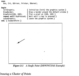
Writing a program that draws a single point is the simplest thing you can do with the Turbo Pascal Graphix Toolbox. Below is a Turbo Pascal program (DRWPNT. PAS on the distribution disk) that draws and displays a single point.
program ExamplePoint; uses
Dos, Crt, GDriver, Printer, GKernel;
begin
InitGraphic; { Initialize (init) the graphics system} DrawBorder; { Draw a border around the default window} DrawPoint(100, 100); { Plot a pixel at (100, 100) }
[image:29.504.81.409.131.445.2]repeat until KeyPressed; { Wait until a key is pressed} LeaveGraphic; { Leave the graphics system} end. { ExamplePoint }
Figure 2-1 A Single Point (DRWPNT.PAS Example)
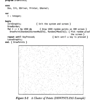
Drawing a Cluster of Points
program DrawPoints;
uses
Dos, Crt, GDriver, Printer, GKernel;
var
I : integer;
begin
InitGraphic;
DrawBorder; { Init the system and screen}
for I := 1 to 1000 do { Draw 1000 random points on IBM screen} DrawPoint{Random{XScreenMaxGlb), Random(YMaxGlb»; { Plot random pixels on
repeat until KeyPressed; LeaveGraphic;
end. { DrawPoints }
: : , ' . ' . "
. ' ' .. ' \
. ' \ I '
" ' , '
.. :' ':'
..
the screen } { Wait until a key is pressed}
t •.
... . ,,'
" "
[image:30.504.83.393.50.393.2].'
Figure 2-2 A Cluster of Points (DRWPNTS.PAS Example)
To allow you to run your program on systems with different graphics cards, you can write this program so that it uses a world coordinate system instead of the absolute screen coordinate system, as described next.
Drawing Points Using a World Coordinate System
A world coordinate system lets you define the addresssing dimensions of your drawing area, independently of the screen type and size. Once you have defined your world, the Turbo Pascal Craphix program will scale the drawing to fit the screen or window you are using.
The following program (WDRWPNTS.PAS on the distribution disk) is identical to the one in the previous section, but uses a world coordinate system instead of the absolute screen coordinate system.
program WorldDrawPoints:
uses
Dos, Crt, GDriver, Printer, GKernel:
var
I : integer:
begin
InitGraphic: DrawBorder:
DefineWorld(l,O,O, 1000, 1000): SelectWorld(1) :
SelectWindow(l):
{ Init the system and screen}
{ Define a world for drawing} { Select it }
for I := 1 to 1000 do { Draw 1000 random points on world} DrawPoint(Random(1000), Random(1000»:
repeat until KeyPressed: { Wait until a key is pressed} LeaveGraphic:
end. { WorldDrawPoints }
Erasing a Point
To erase a point, change the drawing color to black and then draw the point, as follows:
SetColorBlack: DrawPoint(x,y):
Summary of Point Routines
• DrawPoint draws a point in world or screen coordinates. • DP draws a point in absolute screen coordinates only.
• PD returns TRUE if a point is drawn in specified screen coordinates.
Drawing Lines
The DrawLine procedure allows you to draw and display lines in the current line style (selected by the SetLineStyle procedure). The coordinates for lines drawn in the following program examples are all calculated using world coordinate systems.
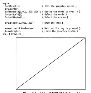
Drawing a Single Line
The following program (DRWLIN.PAS on the distribution disk) draws a line from the upper left to the lower right corner of the screen. Endpoint coordinates are passed to the procedure as the X and Y coordinates of the first endpoint, followed by the X and Y coordinates of the second endpoint.
program DrawLine:
uses
Dos, Crt, GDriver, Printer, GKernel:
begin
InitGraphic: { Init the graphics system} DrawBorder:
DefineWorld(l,O,O,lOOO,lOOO): { Define the world to draw in } SelectWorld(l): {Select the world}
SelectWindow(l): { Select the window}
DrawLine(O,O,lOOO,lOOO):
repeat until KeyPressed: LeaveGraphic:
end. { DrawLine }
{ Draw the line}
[image:32.504.93.385.265.564.2]{ Wait until a key is pressed} { Leave the graphics system}
Figure 2-3 A Line (DRWLIN.PAS Example)
Drawing a "Walking Line»
An intriguing variation on the DrawLine procedure is the "walking line." A walking line program generates, by increments, a series of endpoint coordinates, thereby creating a "walking line." By changing the formula used to generate the endpoint coordinates, a variety of shapes can be drawn. In the example that follows (DRWLINS.PAS on the distribution disk), the first endpoint moves uniformly across the top of the screen from left to right" while the other endpoint moves incrementally and diagonally from the upper right to the lower left corner of the screen.
program DrawLines;
uses
Dos, Crt, GDriver, Printer, GKernel;
var
1 : integer;
begin
InitGraphic;
DefineWorld(1,0,0,1000,1000); SelectWorld(1) ;
SelectWindow(1);
SetBackground(O); DrawBorder;
{ Init the system and screen}
{ Define a world for drawing} { Select it }
{ Set the background color to black}
for 1 := 1 to 20 do { Draw 20 lines} DrawLine(I*50, 0, 1000-1*50, 1*50);
repeat until KeyPressed; LeaveGraphic;
end. { DrawLines }
[image:33.505.66.418.189.578.2]{ Wait until a key is pressed}
Summary of Line-Drawing Routines
• Clip clips a line at active window boundaries.
• DrawLine draws a line using world or screen coordinates.
• Draw Line Clipped clips a line at screen boundaries. • DrawStraight draws a horizontal line.
• SetLinestyle selects one of five linestyles for drawing lines. • GetLineStyle returns the current linestyle.
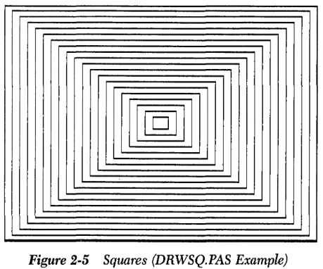
Drawing Squares
The DrawSquare procedure draws rectangles in the current line style (selected by the SetLineStyle procedure). A rectangle is defined by the coordinates of the points at its upper left and lower right corners. A Boolean value, Fill allows you to fill the rectangle with the current drawing color (determined by the SetForegroundColor procedure). The following program (DRWSQ.PAS on the distribution disk) draws a series of consecutively larger squares around the center of the screen, with no fill. Another example program not illustrated here (DRWHCH.PAS on the distribution disk) draws hatched squares.
program DrawSquares;
uses
Dos, Crt, GDriver, Printer, GKernel;
var
1 : integer;
begin
InitGraphic;
DefineWorld(l,O,O,lOOO,lOOO); SelectWorld(1) ;
SelectWindow(l); DrawBorder;
{ Init the system and screen}
{ Define a world for drawing} { Select it }
for 1 := 1 to 20 do { Draw 20 squares}
DrawSquare(500-1*25, 500-1*25, 500+1*25, 500+1*25, false);
repeat until KeyPressed; LeaveGraphic;
end. { DrawSquares }
Getting Started
{ Wait until a key is pressed}
-Figure 2-5 Squares (DRWSQ.PAS Example)
Summary of Square-Drawing Routines
• DrawSquare draws a square using world coordinates.
• DrawSquareC draws a square using screen. coordinates, but clipped at the boundaries of the active window.
• SetForegroundColor chooses the current drawing color. • SetLinestyle chooses the line style.
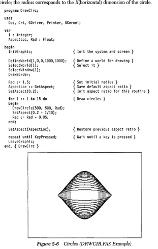
Drawing Circles
Because different graphics cards produce screen displays with different vertical-by-horizontal dimensions, and because different monitors have different screen proportions, a correctly-proportioned circle drawn on one screen may look dis-torted on another screen. To adjust for differences in screen proportions, Turbo Graphix routines that deal with circles and ellipses - DrawCircle, DrawCircleSeg-ment, DrawCartPie and DrawPolarPie-utilize the concept of the aspect ratio.
[image:35.505.130.360.32.223.2]The following program (DRWCIRPAS on the distribution disk) draws a series of circles, and varies both their radii and aspect ratios. The parameters passed to the
DrawCircle procedure specify the X and Y world coordinates of the center of the
circle; the radius corresponds to the X(horizontal) dimension of the circle.
program DrawCirc; uses
Dos, Crt, GDriver, Printer, GKernel; var
I : integer;
AspectLoc, Rad Float; begin
InitGraphic; { Init the system and screen}
DefineWorld(l,O,O,1000,1000); Sel ectWorl d (1);
SelectWindow(l); DrawBorder; Rad := 1.5;
AspectLoc := GetAspect; SetAspect(0.2):
for I := 1 to 15 do begin
DrawCircle(500, 500, Rad); SetAspect(0.2 + 1/10); Rad := Rad - 0.05; end;
SetAspect(AspectLoc):
repeat until KeyPressed: LeaveGraphic;
end. { DrawCirc } .
{ Define a world for drawing} { Select it }
{ Set initial radius} { Save default aspect ratio}
{ Init aspect ratio for this routine}
{ Draw circles}
[image:36.505.92.403.87.576.2]{ Restore previous aSRect ratio} { Wait until a key is pressed}
Figure 2-6 Circles (DRWCIR.PAS Example)
Summary of Related Routines
• DrawCircle draws a circle or ellipse using world or screen coordinates.
• DrawCircleDirect draws a circle or ellipse using screen coordinates.
• DrawCircleSegment draws an arc of a circle.
• DrawPie draws a pie chart.
• GetAspect returns the current aspect ratio.
• SetAspect determines the aspect ratio for a circle.
Text
As explained in Chapter 1, the Turbo Pascal Graphix Toolbox supports both a 4x6-pixel text and a machine-dependent text. The size of machine-dependent chanic-ters is 8x8 pixels for IBM CGA and AT&T, and 9x14 pixels for Hercules, IBM EGA, and IBM 3270.
Displaying Machine-Dependent Text
The text routines used by the Turbo Pascal Graphix Toolbox are very similar to those used by Turbo Pascal; the screen is defined as 25 lines by 80 columns (char-acters), and the Turbo Pascal procedures GataXY, Write and WriteLN are sup-ported by the Graphix Toolbox. However, there are a few considerations specific to the Turbo Pascal Graphix text mode concerning the alignment of text with draw-ings, and within windows. Since the size of the text font varies with the graphics card installed, some adjustments must be made when attempting to align text with drawings. In particular, Hercules text, which is defined on a 9-pixel horizontal boundary, must be adjusted for the 8-pixel window boundary. See Appendix A for technical information on text fitting.
program DrawStandardText;
uses
Dos, Crt, GDriver, Printer, GKernel;
const MaxWorldX MaxWorldY
var
I integer;
Float = 1000.0; Float = 1000.0;
CharHeight, CharWidth Float;
begin
InitGraphic; { Init the graphics system}
DefineWorld(l, 0, 0, MaxWorldX, MaxWorldX); { Define the world to draw in } SelectWorld(l); { Select the world and window}
SelectWindow(l); DrawBorder;
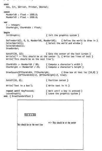
GotoXY(39, 12); { Goto the center of the text screen} Writeln('* <- This should be at the center '); { Write two lines of text} Write('This should be on the next line');
CharWidth := MaxWorldX / 80; CharHeight := MaxWorldY / 25;
{ Compute a character's width} { Compute a character's height}
DrawSquare(9*CharWidth, 7*CharHeight, { Draw box at text loc [10,8] } (22*CharWidth)+2, (8*CharHeight)+2, true);
GotoXY (10, 8);
Write('Text in a box');
repeat until KeyPressed; LeaveGraphic;
end. { DrawStandardText }
[ext In a boxl
his should he on the next line
{ Position cursor}
{ Write text in it }
{ Wait until a key is pressed} { Leave the graphics system}
* (-
This should he at the centerFigure 2-7 Machine-Dependent Text (DRWSTXT.PAS Example)
[image:38.507.94.440.58.571.2]Displaying 4x6 Pixel Text
The 4x6 pixel character set is used for window headers, and for applications that require text that is smaller or larger than the machine-dependent text. Unlike the machine-dependent text, the 4x6 pixel characters can be placed at any screen loca-tion. The Scale parameter passed to the DrawText procedure specifies the size of the characters (in integer multiples of 4x6 pixels); the larger the value of Scale, the larger the character.
Since a character in the 4x6 pixel font is made up of only a few pixels, this text is of a coarser quality than the machine-dependent text, even when they are scaled to the same size.
The following example (DRWATXT.PAS on the distribution disk) uses the Draw-Text procedure to display upper-case characters, in different positions and sizes, in the center of the screen. The complete character set is then displayed at the upper left corner of the screen, scaled to its smallest size.
program DrawAlternateText;
uses
Dos, Crt, GDriver, Printer, GKernel;
Float = 1000.0; Float = 1000.0; const
MaxWorldX MaxWorldY
CharArray1 array [0 .. 25] of char = { Define an array of characters} ('A', 'B', 'C', 'D', 'E', 'F', 'G', 'H', 'I', 'J', 'K', 'L', 'M',
'N', '0', 'P', 'Q', 'R', '5', 'T', 'U', 'V', 'W', 'X', 'Y', 'Z');
var
I : integer;
CharHeight, CharWidth Float;
begin
InitGraphic; { Init the graphics system}
DefineWorld(l, 0, 0, MaxWorldX, MaxWorldY); {Define the world to draw in } 5electWorld(1) ;
5electWindow(1); DrawBorder;
for I := 1 to 50 do { Print Random characters in center of screen} DrawTextW(Random(600) + 200, Random(600) + 200,
Random(5), CharArray1[Random(26)]);
DrawTextW(15, 50, 1, 'ABCDEFGHIJKLMNOPQR5TUVWXYZ'); { Type chars in corner} DrawTextW(15, 100, 1, 'abcdefghijklmnopqrstuvwxyz');
DrawTextW(15, 150, 1, '1234567890-=\--!@#$%~&*()_');
DrawTextW(15, 200,1, '[]{}:";,.<>/?+I');
repeat until KeyPressed; LeaveGraphic;
end. { DrawAlternateText }
ABCOEFGHllKLnHCPQRS1UU~~il l~Calf~h i iklKnOPQrSlUVwKYZ
lmmSlO-:I"!eI$1.'U(I.,I tlU:';,.O/1
~
Ut
s
~J
~B'~
f
~
R RH
D
~
H
~
P
y
[image:40.507.145.375.48.227.2]y
~Q
Figure 2-8 4x6 Pixel Text (DRWATXT.PAS Example)
Summary of Text-Drawing Routines
For machine-dependent text:
DC draws a character at the specified text coordinates.
• DefineTextWirulow uses specified text coordinates to define a window. • DisplayChar draws a character at the specified text coordinates.
• TextDown, TextLejt, TextRight, TextUp adjust space between window bound-aries and text (text fitting).
For 4x6 pixel text:
• DefineHeader defines a window header.
• DrawAscii draws a character at the specified screen coordinates. • DrawText draws a character string at the specified screen coordinates. • DrawTextW draws a character string at the specified world coordinates~
Windows
This section tells you how to create and manipulate on-screen windows. The use of windows allows greater flexibility in graphics applications, since you can display several different drawings on the screen at once, using different world coordinate systems; and you are not limited to the pixel dimensions of the window.
Defining a Window
When the Turbo Pascal Graphix Toolbox is initialized with the InitGraphic proce-dure, the entire screen is, in effect, defined as a window whose world coordinates correspond to the pixel dimensions of the screen. However, you can redefine any region of the screen as a window, from an 8xl pixel (horizontal by vertical) box. to the entire screen.
Once defined, a window acts more or less independently of other windows and even the screen. Windows can be small or large, moved around, drawn on with reference to their own coordinate systems and boundaries, and individually removed, stored, and retrieved.
Generally, you will want to define a new world coordinate system for every window you define; otherwise, any drawing you do in a window will take place as if the screen coordinate system were mapped to that window. All drawing routines-except routines internal to the graphics system, routines for machine-dependent text positioning such as GotoXY, and window positioning routines - can use world coordinate systems.
To associate a world with a window, you must always call SelectWorld before SelectWindow. If a new window is subsequently selected, the current world is retained. Thus, to draw alternately in two windows with different worlds, SelectWorld must be called before each SelectWindow:
repeat
SelectWorld(1) i SelectWindow(l)i
{ Insert code to draw something in window 1 using world coordinate system 1 } SelectWorld(4)i
SelectWindow(2)i
{ Insert code to draw something in window 2 using world coordinate system 4 } until KeyPressedi
Besides simply defining the dimensions of your window, you can label it with a header or footer, fill it in with a color or background pattern, or draw a border around it in any line style. When a new window is defined or an existing window is redefined, the header associated with that window number is destroyed. This means that Define Window must be called before DefineHeader.
To change the dimensions of an existing window, without changing its header, use the Redefine Window procedure.
program SimpleWindow;
uses
Dos, Crt, GDriver, Printer, GKernel, GWindow;
begin
InitGraphi c;
DrawBorder;
{ Init the graphics system}
{ Draw a border around the drawing} { area of the primary window}
DefineWindow(l, 10, 20, XMaxGlb-lO, YMaxGlb-20);
{ Define a window 80 pixels in from} { the left and right edges, and 20 } { from the top and bottom edges }
DefineHeader(l,'THIS IS AN EXAMPLE WINDOW ' ); { Give it a header} SetHeaderOn;
DefineWorld(l,O,O,lOOO,lOOO); {Give it a world coordinate system}
SelectWindow(l);
SelectWorld(1) ;
SetBackground(85);
DrawBorder;
{ Select the window}
{ Select the world}
{ Give it a grey background}
{ Draw the border }
repeat until KeyPressed; { Wait until a key is pressed}
{ Leave the graphics system} LeaveGraphic;
end. { SimpleWindow }
[image:42.505.103.375.216.544.2]• • IHISISANEXAMFLEUlHOCU
Figure 2-9 A Window (SIMPWIND.PAS ExamplE)
Displaying a Drawing in a Window
Suppose you want to display the "walking line" example in a window. You can display the example using a world coordinate system, and in any position on the screen by following these steps:
• Define the window
• Define the world coordinate system for the window
• Select the world coordinate system
• Select the window for drawing
• Draw a border (optional)
• Display the walking lines
The following example (MULTWIND.PAS) displays the walking line example in three different windows, each with its own coordinate system, with the drawings clipped at window boundaries.
program MultipleWindows;
uses
Dos, Crt, GDriver, Printer, GKernel;
var
I : integer;
procedure DrawLines;
var
I : integer; beg;n
for I := 1 to 20 do
DrawLine(1 * 50, 0, 1000 - I * 50, I * 50); end; { DrawLines }
beg;n
InitGraphic; { Init the graphics system}
DrawBorder; { Draw a border around the drawing} { area of the primary window'}
{ (the dimensions of the primary window} { default to the screen dimensions) }
DefineWindow(l, Trunc(XMaxGlb / 10), Trunc(YMaxGlb / 10), Trunc(XMaxGlb / 2), Trunc(YMaxGlb / 2));
{ Define a window one tenth of the way} { in from the left and top edges, and half} { way down from the right and bottom edges}
DefineHeader(l, 'THIS IS A LARGER WORLD'); { Give it a header}
DefineWindow(2, Trunc(XMaxGlb / 3), Trunc(YMaxGlb / 3),
Trunc((XMaxGlb * 2) / 3), Trunc((YMaxGlb * 2) / 3) ); { Define a window one third of the way} { in from the left and top edges, and} { from the right and bottom edges}
DefineHeader(2, 'THIS IS A CORRECT WORLD'); { Give it a header}
DefineWorld(2, 0, 0, 1000, 1000); { Give it a correct world} { coordinate system}
DefineWindow(3, Trunc(XMaxGlb / 2), Trunc(YMaxGlb / 2),
Trunc((XMaxGlb * 9) / 10), Trunc((YMaxGlb * 9) / 10»; { Defin~ a window one half of the way} { in from the left and top edges, and half} { way down from the right and bottom edges}
DefineHeader(3, 'THIS IS A SMALLER WORLD'); { Give it a header}
DefineWorld(3, 0, 0, 500, 500); { Give it a smaller world coordinate system}
for I := 1 to 3 do begin
SelectWindow(I); SetHeaderOn; Se 1 ectWorl d (I) ;
SetBackground(O); DrawBorder; DrawLines; end;
repeat until KeyPressed;
LeaveGraphic;
end. { MultipleWindows }
{ Select window}
{ Set the window header on } { Select a world coordinate system} { Give the window a black background} { Draw a border around the window} { Draw lines}
{ Wait until a key is pressed}
{ Leave the graphics system}
Figure 2-10 Three Wirulows (MULTWIND.PAS Example)
[image:44.507.96.381.241.559.2]Moving Windows
Once you've defined a window, you can move it to any position on the screen using the Move Ver and MoveHor procedures; windows are moved by increments (multi-ples of 8 horizontal pixels and multi(multi-ples of 1 vertical pixel).
MoveHor and Move Ver work by automatically and continually refreshing the screen images over which the window is moved. They do this by storing the dis-played screen image to the virtual screen.
If you want to move multiple windows, things' get a bit more complicated; you must manage the windows and other screen images yourself. What this means is that you must continually rebuild the virtual screen image every time you move windows. If there are any images on the screen that you wish to keep, you must copy those images either to the window stack with the Store Window procedure (if the images are in a window) or to the RAM (virtual) screen with the CopyWindow or Copy-Screen procedure (if the images are on the screen) so they can be retrieved later; otherwise, when you move a window over those images, they will be erased, and there will be no way to restore them.
For your windows to keep their integrity and to be moved independently, you must keep copies of all windows on the window stack, and store all screen images you want to keep on disk. For instance, if the screen contains two windows that you want to display independently - that is, you want to be able to move them around and place them on top of each other - you should do the following: using the Save-Screen procedure, store the screen (without any windows) on disk, and store up-to-date copies of both windows on the window stack using the Store Window proce-dure.
Every time you draw something in a window, or change what was previously drawn, save a copy of the window on the window stack. When you want to move a window, save the presently displayed screen - without the window you plan to move-to the RAM virtual screen using the CopyScreen procedure, so the nOQ-moving window is now also copied to the virtual screen. The virtual screen should now contain everything that was on the displayed screen, except the window you want to move. Now, draw the window you want to m.ove on the screen, and use MoveHor and Move Ver to move the window around, without destroying the fixed images underneath.
Windows can be restored from the stack to any location on the screen by specifying X and Y offsets. To restore the window to its former position, use offsets of O.
If the window currently selected with the SelectWindow procedure is the same as the one being restored from the stack, the screen coordinates of the selected win-dow will shift to match the offset of the restored winwin-dow. The selected winwin-dow does oot change when any other window is restored from the stack.
Stored windows and the RAM screen are dynamically allocated on the heap using the Turbo GetMem and FreeMem procedures. Therefore, the Mark/Release method of memory management should not be used in your programs.
The following program (MOVEWIND.PAS) shows how to move windows about on the screen; use the arrow keys to move the windows, and press the space bar to stop program execution.
program MoveWindows;
uses
Oos, Crt, GOriver, Printer, GKernel, GWindow;
const Null= #0;
var
I : integer; Ch : char;
procedure OrawLines; var
I : integer; begin
for I := 1 to 20 do
{ The null character}
OrawLine(1 * 50, 0, 1000 - I * 50, I * 50); end; { DrawLines }
begin { MoveWindows }
InitGraphic; { Init the graphics system}
DrawBorder; { Draw a border around the drawing} { area of the primary window}
{ (the dimensions of the primary window} { default to the screen dimensions) }
DefineWindow(l, Trunc(XMaxGlb / 10), Trunc(YMaxGlb / 10), Trunc(XMaxGlb / 2), Trunc(YMaxGlb / 2));
{ Define a window one tenth of the way} { in from the left and top edges, and half} { way down from the right and bottom edges}
DefineHeader(l, 'THIS IS THE FIXED WINDOW ' ); {Give it a header}
DefineWorld(l, 0, 0, 1000, 1000): {Give it a world coordinate system}
DefineWindow(2, Trunc(XMaxGlb / 2), Trunc(YMaxGlb / 2),
Trunc«XMaxGlb * 9) / 10), Trunc«YMaxGlb * 9) / 10»: { Define a window one half of the way} { in from the left and top edges, and half} { way down from the right and bottom ~dges }
DefineHeader(2, 'THIS IS THE MOVEABLE WINDOW'): { Give it a header}
DefineWorld(2, 0, 0, 1000, 1000): {Give it a world coordinate system}
SelectWindow(l): SetHeaderOn: SelectWorld(1): SetBackground(O): DrawBorder: DrawLines: CopyScreen: SetBreakOff: SetMessageOff: SelectWindow(2): SetHeaderOni SelectWorld(2); SetBackground(O)i DrawBorder: DrawLines: repeat
Ch: = Readkey:
{ Select fixed window}
{ Select its world}
{ Give it a black background} { Draw a border around the window} { Draw lines in it }
{ Copy it to the virtual screen}
'{ Don't error when edge hit}
{ Select moveable window}
{ Select its world}
{ Give it a black background} { Draw a border around the window} { Draw lines in it }
{ Read the' keystroke }
if (Ch = Null) and KeyPressed then { Test for an extended scan code } Ch: = ReadkeYi { on either an IBM or Zenith Z100 }
case Ch of
'A' , 'H' 'D' , 'K'
'C' , 'M'
'B' , ' P'
end: until Ch =
,
LeaveGraphic:':
MoveVer(-4, true): MoveHor(-l, true): MoveHor(l, true): MoveVer(4, true):
{ Up arrow } { Left arrow} { Right arrow} { Down arrow }
{ Space character exits program}
{ Leave the graphics system}
THI:IilHEFIHomocu
[image:48.510.136.424.42.248.2]IHH I: THE nC~mLE UIHOCU .
Figure 2-11 Moving a Window (MOVEWIND.PAS Example)
Another Use for Windows: The Flow Chart
Anything that can be contained in a rectangle can be animated using windows. The following example (FLOWDEMO.PAS) animates a How chart by using a moving window. The drawing of the How chart is the fixed screen image, while a window that contains the present state of the "machine" is moved along the How chart drawing to show how the processor modifies variables when the program executes. The program increments a count and tests the result. If the count is not large enough, the program increments the count and tests again. When the count is high enough, the program is finished.
program FlowOemo;
uses
Dos, Crt, GOriver, Printer, GKernel, GWindow;
procedure FlowChartDemo; var
Xl, YI, X2, Y2, I, Count: integer; Temp: WrkString;
procedure DrawArrowHor(XI, YI, X2, Y2 : integer); { Draw horizontal arrow with tip at point (X2, Y2) } begin
DrawLine(XI, YI, X2, Y2);
if X2 > Xl then begin
OrawLine(X2 - 4, Y2 - 2, X2, Y2); DrawLine(X2 - 4, Y2 + 2, X2, Y2); end
else
begin
DrawLine(X2 + 5, Y2 - 2, X2, Y2); DrawLine(X2 + 5, Y2 + 2, X2, Y2); end;
end; { DrawArrowHor }
procedure DrawArrowVer(Xl, Yl, X2, Y2 : integer); { Draw vertical arrow with tip at point (X2, Y2) } begin
DrawLine(Xl, Yl, X2, Y2); if Y2 > Y1 then
begin
DrawLine(X2 - 2, Y2 - 3, X2, Y2); DrawLine(X2 + 2, Y2 - 3, X2, Y2); end
else begin
DrawLine(X2 - 2, Y2 + 3, X2, Y2); DrawLine(X2 + 2, Y2 + 3, X2, Y2); end;
end; { DrawArrowVer }
procedure Blink(Count, Time: integer); { Blink the current window}
var
I : integer; begin
for I := 1 to Count do begin
Del ay(Time); InvertWindow; end;
end; { Blink}
begin { FlowChartDemo }
DefineWindow(I, 0, 0, 79, 185); DefineWindow(2, 12, 20, 25, 40); DefineWindow(3, 15, 55, 22, 75); DefineWindow(4, 11, 110, 26, 130); DefineWindow(5, 47, 90, 56, 110);
ClearScreen; SetColorWhite;
DefineHeader(l, 'A FLOW CHART ' ); SetHeaderOn; SelectWindow(I); DrawBorder; SetHeaderOff; SelectWindow(2); DrawBorder;
DrawText(125, 27, 2, 'START ' ); SetWindowModeOff;
DrawArrowVer(151, 40, 151, 55); SetWindowModeOn;
{ Define the I FLOW CHART I window}
{ Define the 'START ' window} { Define the 11=11 window} { Define the 'IF 1<=5 1 window} { Define the 11=1+11 window}
{ Draw the surrounding window}
{ Draw the I START I window}
SelectWindow(3); DrawBorder;
DrawText(136, 63, 2, 11=11); SetWindowModeOff;
DrawArrowVer(151, 75, 151, 110); SetWindowModeOn;
SelectWindow(4); DrawBorder;
DrawText(108, 118, 2, IIF 1<=5 1); DrawStraight(215, 417, 120); SetWindowModeOff;
DrawArrowVer(417 , 120, 417, 110); DrawArrowVer(151, 130, 151, 155); SetWindowModeOn; .
SelectWindow(l);
DrawText(300, 110, 2, IYES I); DrawText(160, 137, 2, INO I);
SelectWindow(5); DrawBorder;
DrawText(390, 98, 2, 11=1+11); SetWindowModeOff;
DrawLine(417, 90, 417, 80); DrawArrowHor(417, 80, 151, 80);
SetAspect (1. 0) ;
DrawCircle(151, 165, 25); SelectWindow(l);
DrawText(137, 163, 2, IENDI); SetWindowModeOn;
SetHeaderOn;
CopyScreen;
DefineWindow(2, 15, 21, 22, 39); SelectWindow(2); SetBackground(O); DrawBorder; InvertWindow; Delay(1000); InvertWindow;
Temp : = 1123456 I ; MoveVer(35, true);
DrawText(139, 63, 2, 11=1 + Temp[l]); Blink(30, 50);
MoveVer(55, true);
for Count := 2 to 6 do
Getting Started
{ Draw the 11=11 window}
{ Draw the connecting line}
{ Draw the IIF 1>=5 1 window}
{ Draw the connecting lines}
{ Draw the 11=1+11 window}
{ Draw the connecting lines}
{ Draw the