R E S E A R C H
Open Access
Power-optimized log-based image processing
system
Vaithiyanathan Dhandapani
*and Seshasayanan Ramachandran
Abstract
The continuous development of devices such as mobile phones and digital cameras has led to a higher amount of research being dedicated to the image processing field. Today's image-acquiring tools require battery-operated power, and hence, power optimization becomes a major factor to be considered in the hardware implementation of image systems. This paper proposes an image processing system which utilizes set partitioning in hierarchical trees (SPIHT)-integrated discrete wavelet transform (DWT) structure for image processing. The overall advantage of this proposal is achieved by modifying the arithmetic units in the DWT structure. Utilizing a logarithm-based floating point unit (FPU) in the DWT computation structures, the logarithmic number system (LNS) adaptation in the arithmetic unit results in overall accuracy enhancement with reduced area and power consumption. To ensure the versatility of the proposal and for further evaluating the performance and correctness of the structure, the model is implemented using Xilinx and Altera field-programmable gate array (FPGA) devices. The analyses obtained from the implementation show that the structure incorporated with the log-based FPU is 25% more accurate with 47% reduced power consumption than the integer-styled FPU incorporated DWTs, along with enhanced speed and optimal area utilization.
Keywords:Discrete wavelet transform (DWT); Lifting scheme; Log principles; Floating point unit (FPUs); Set partition in hierarchical trees (SPIHT); Image coding; Field-programmable gate array (FPGA) implementation; Real-time processing
1 Introduction
Discrete wavelet transform (DWT) is increasingly being used for image coding. In particular, biorthogonal sym-metric wavelets manifested remarkable abilities in still image compression. Hence, this paper proposes an image processing system by focusing on the biorthogonal 9/7 DWT structure. DWT has traditionally been implemented using the convolution method. This implementation de-mands a large number of computations and storage fea-tures that are not desirable for high-speed or low-power applications. Swelden [1] proposed a new mathematical formulation for wavelet transformation based on spatial construction of the wavelets, and a very versatile scheme for its factorization has been suggested in [2]. This ap-proach is called the lifting-based wavelet transform. The main feature of the lifting-based DWT scheme is to break up high-pass and low-pass filters into a sequence of upper
and lower triangular matrices and convert the filter imple-mentation into banded matrix multiplications. This scheme has several advantages when compared to the convolution techniques, which includes ‘in-place’ computation of the DWT, symmetric forward, and inverse transform. There-fore, the DWT implemented using the lifting scheme in the JPEG 2000 standard are the biorthogonal lossless 5/3 inte-ger and the lossy 9/7 floating point filter banks. Numerous architectures have been proposed in order to provide low-power, high-speed, and area-efficient hardware implemen-tation for DWT compuimplemen-tation [3-16]. Shi et al. [6] proposed efficient folded architecture (EFA) with low hardware com-plexity. The flipping structure is another important DWT architecture that was proposed by Huang et al. [7]. A high-speed, reduced-area two-dimensional (2-D) DWT archi-tecture was proposed by Zhang et al. [10]. While most of these architectures are related to research involved in the optimization of critical paths, only some of them, such as Lee et al. [16], deal not only with the internal data path but also with the coefficient precision optimization.
* Correspondence:[email protected]
Department of Electronics and Communication Engineering, Anna University, Chennai, Tamil Nadu 600 025, India
operations, acting like an additional prop up for normal ALUs. An island-style with embedded FPU [17] is proposed by Beauchamp et al., while a coarse-grained FPU was suggested by Ho et al. [18]. Even et al. [19] suggests a multi-plier for performing on either single-precision or double-precision floating point numbers. An optimized FPU in a hy-brid FPGA was suggested by Yu et al. [20] and a configurable multimode FPU for FPGAs by Chong and Parameswaran [21]. Performance improvisation and optimization of these suggested models are studied and employed in each succes-sive development time frame. However, while these models fine tune the FPU in terms of area, there were no suggestions for power reduction or accuracy enhancements. Anand et al. [22] proposed a log lookup table (LUT)-based FPU, which utilizes a logarithmic principle to achieve good accuracy with reduced power consumption. However, this model has some serious drawbacks, which include increased delay and additional memory for the log LUT handling. The above factors affect the performance in terms of area and speed. Hence, this proposed scheme suggests an ef-ficient model for performing floating point operations to reduce power consumption by reducing the operation complexities using log conversion [23].This reduces the overall computation burden, as the process is simply a nu-merical transformation to the logarithmic domain. Thus, a reduction in power consumption and increased accuracy is attained with optimal area usage [24]. The mere map-ping of floating point numerals is not possible, and hence, a standardized form is adopted by using IEEE 754 single-precision floating point standard [25]. An optimized DWT architecture with log-based FPU is proposed, and a preliminary version of this work was presented in [26]. This paper revises the external memory access, and a more accurate and detailed error analysis and the simula-tion results are given.
After the lifting-based DWT was introduced, several coding algorithms were proposed to code the wavelet coefficients into an efficient result, while taking storage space and redundancy into consideration. These algo-rithms are embedded zerotree wavelet (EZW), embed-ded block coding with optimized truncation (EBCOT), and set partitioning in hierarchical trees (SPIHT). Among these, the SPIHT algorithm is most preferable because of its low-computational complexity and better image com-pression performance. The SPIHT coding, proposed by
put, Cheng et al. [31] proposed a modified SPIHT that processes a 4 × 4 bit plane in 1 cycle. Fry and Hauck [32] improvised this model with a bit plane parallel SPIHT encoder architecture to further increase the throughput. By the year 2013, Jin and Lee [33] proposed a block-based pass-parallel SPIHT (BPS) algorithm, which em-ploys pipelining and parallelism. This scheme has the highest throughput among the existing architectures. Hence, we espouse the BPS in our image processing core.
This proposal introduces an enhanced image process-ing system, which utilizes a low-power DWT structure along with a log-based FPU and BPS coder. The opti-mized decomposition level of DWT is selected based on performance parameters such as peak signal-to-noise ratio, compression ratio, and computational complexity. To examine the specific hardware performance and trade-offs associated with the solutions presented here, the architecture is first verified in Matlab for the image parameters. In addition to this, the hardware implemen-tation is carried out using Verilog hardware description language (HDL) and synthesized using Xilinx and Altera FPGA families to verify its device level performance based on VLSI parameters.
The rest of the paper flow is given in brief as follows. Section 2 gives the background supporting the basic un-derstanding of lifting-based discrete wavelet transform and SPIHT coding techniques. Section 3 pursues with the hardware implementation of forward 2-D DWT with modified computation unit adopting log-based FPU and SPIHT coders. Detailed experimental setup for the pro-posed real-time image processing system and the per-formance of the proposed architecture is assessed and compared with that of other existing architectures are given in Section 4. Conclusion and final remarks are given in Section 5.
2 Background
2.1 Discrete wavelet transform 2.1.1 Lifting scheme
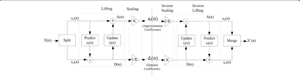
then alternating primal lifting and dual lifting steps, and finally the inverse lazy transform. The inverse transform can immediately be derived from the forward transform by running the scheme backwards and flipping the signs as shown in Figure 1.
The lifting scheme implements a filter bank as a multipli-cation of upper and lower triangular matrices, where each matrix constitutes a lifting step [1,2]. Leth z~ð Þ and~g zð Þbe the low-pass and high-pass analysis filters, respectively, and leth(z) andg(z) be the low-pass and high-pass synthesis fil-ters, respectively. The corresponding polyphase matrices are defined as:
~
P zð Þ ¼ ~heð Þz h~oð Þz ~
geð Þz g~oð Þz
and P zð Þ ¼ heð Þz geð Þz hoð Þz goð Þz
ð1Þ
whereh~e contains the even coefficients andh~ocontains the odd coefficients:
~ heð Þ ¼z
X
k
h2kz−k and ~hoð Þ ¼z X
k
h2kþ1z−k ð2Þ
It has been shown that if~h;~gis a complementary filter pair, the Euclidean algorithm can be used to decomposeP~
z
ð Þ. ThisP z~ð Þcan always be factored into lifting steps as
~
P zð Þ ¼ Πm i¼1
1 sið Þz
0 1
1 0
tið Þz 1
K 0
0 1=K
ð3Þ
The lifting wavelet transform consists of three steps as in Figure 1:
1. Spliting. The original signalX(n) is split into odd and even sequences (lazy wavelet transform)
Xeð Þ ¼n Xð Þ2n ð4Þ
Xoð Þ ¼n Xð2nþ1Þ ð5Þ
2. Lifting.It consists of one or more stepsmof the form (a)Predict/Dual lifting.IfX(n) possesses local
correlation, thenXe(n) andXo(n) also have local
correlation. Therefore, one subset is used to predict the other subset. In the prediction step, the filtered even array is used to predict the odd array. The new odd array is redefined as the difference between the existing array and the predicted one.
D nð Þ ¼Xoð Þn −siðXeð ÞnÞ ð6Þ
(b)Update/Primal lifting. To eliminate aliasing which appears due to the down sampling of the original signal, the even array is updated using the filtered new odd array.
A nð Þ ¼Xeð Þ þn tiðD nð ÞÞ ð7Þ
Eventually, aftermpairs of prediction and update steps, the even samples become the low-frequency component while the odd samples become the high-frequency component.
3. Normalization/Scaling.Aftermlifting steps, scaling coefficientsKand 1/Kare applied respectively to the even and odd samples in order to obtain the low-pass subband and high-low-pass subband.
For the biorthogonal 9/7 wavelet, four lifting steps and one scaling can be used, wheres1(z) =α(1 +z−1), s2(z) =
γ(1 +z−1), t1(z) = β(1 +z), and t2(z) = δ(1 +z). The
pa-rametersα,β,γ, andδare two-tap symmetric filter coef-ficients andKand 1/Kare scaling factors.
Lifting steps:
PredictP1:di1ð Þ ¼n Xoð Þ þn α½Xeð Þ þn Xeðnþ1Þ
ð8Þ UpdateU1:ai1ð Þ ¼n Xeð Þ þn β di1ðn1Þ þdi1ð Þn
ð9Þ PredictP2: di2ð Þ ¼n di1ð Þ þn γ ai1ð Þ þn ai1ðnþ1Þ
ð10Þ
UpdateU2: ai2ð Þ ¼n ai1ð Þ þn δ di2ðn−1Þ þdi2ð Þn
ð11Þ
Scaling:
aið Þ ¼n Kai2ð Þn ð12Þ dið Þ ¼n 1=Kdi2ð Þn ð13Þ where α=−1.586134342, β=−0.05298011854, γ= 0.8829110762,δ= 0.4435068522, andK= 1.149604398
The original data to be filtered is denoted byX(n), and the outputs areaianddiwhich are the approximation
co-efficients and detail coco-efficients, respectively. We focus on the implementation issue of the lifting-based DWT, which yields higher computational complexity with floating point computation. Hence, we suggest an efficient model for performing the floating point operation to reduce the power by reducing the operating complexities by adop-ting log conversion [22,23].
2.2 Set partition in hierarchical trees
SPIHT algorithm is applied to a wavelet-transformed image, in which a transformed image can be organized as a spatial orientation tree (SOT) shown in Figure 2a. The arrow in Figure 2a represents the relationship be-tween a parent and its offspring, and each node of the tree corresponds to a coefficient in the transformed image. The SPIHT scans the DWT coefficients in Mor-ton scanning order as shown in Figure 2b. It also assigns the parent-child hierarchy on the scanned coefficients.
For a given set T, SPIHT defines a function of signi-ficance, which indicates whether the setThas pixels lar-ger than a given threshold. Sn(T), the significance of set
Tin thenth bit plane, is defined as in Equation 14.
Snð Þ ¼T
1; max
w ið Þ;j∈T w ið Þ;j
j j
ð Þ≥2n
0; otherwise
( )
ð14Þ
Figure 2Spatial orientation trees in SPIHT (a) and Morton scanning order of a 16 × 16 three-level wavelet-transformed image (b).
Note: w(i,j) is the coefficient value for (i,j) position in the wavelet domain. Tstands for the set of coefficients andSn(T) is used for significant state ofTat bit planen.
When Sn(T) is ‘0’, T is called an insignificant set.
Otherwise,Tis called a significant set. An insignificant set can be represented as a single bit ‘0’. The cant set is partitioned into subsets, and its signifi-cances have to be tested again based on the zerotree hypotheses. The SPIHT encodes a given set T and its descendants (denoted by D(T)) together by checking the significance ofT∪D(T) and by representingT∪D (T) as a single symbol ‘0’ if T∪D(T) is insignificant. On the other hand, if T∪D(T) is significant, T has to partitioned into subsets and each subset is tested independently.
The spatial orientation trees are illustrated in Figure 2b for a 16 × 16 image and is transformed by three levels of discrete wavelet decomposition. Each level is divided into four subbands. The subband a2a2 is divided into
four groups of 2 × 2 coefficients. In each group, each of the four coefficients becomes the root of a spatial orientation tree. The square denoted byRin Figure 2a represents the subband a3a3 (low pass subband) in
Figure 2b, which corresponds to the root. In order to increase the speed of both the encoder and decoder, we adopt a BPS algorithm [33] for our image process-ing core. BPS algorithm modifies the processprocess-ing order of the original SPIHT algorithm so that an image is partitioned into multiblocks, and the coefficients trees are local to these blocks. Furthermore, BPS employs
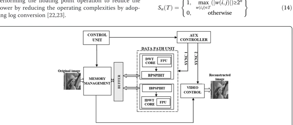
Figure 4Memory management system.
pipelining and parallelism, which gives the highest throughput among the existing architectures.
3 Proposed architecture
Figure 3 shows a hierarchical placement of different cores, which all together form the proposed enhanced image processing system. The system incorporates a DWT structure with a BPS, and the overall flow is being moni-tored using three different control units with proper synchronization signals. The functions and nature of each block are discussed as follows.
3.1 Discrete wavelet transform core
The memory issue and multiplier implementation is the most critical part of the hardware implementation of 2-D 2-DWT. In general, the memory-based architecture can be classified into three categories: level-based, line-based, and block-based methods [34]. Based on the hardware constraints required, any of above methods could be se-lected. However, the external memory access would con-sume the most power and would require more bandwidth. This system uses line-based processing for implementing the 2-D DWT architecture. This method uses embedded memory, which acts as a buffer between the row and col-umn processing and thus avoids the heavy dependence on external memory. The inputs for the system are fed from a memory management system as shown in Figure 4. This comprises of a memory block, which frequently updates at regular intervals based on the sync signals from the
control blocks. The sync signals are generated for match-ing the overall delay, which consist of two critical path de-lays (Tmul+ 2Tadder).
In hardware implementation, the multiplier occupies a large amount of hardware resources. In order to provide a low-power, high-speed, and area-efficient multiplier for DWT computation, Shi et al. [6] adopted the shift-add operations to optimize the multiplications since the co-efficients of wavelet filters are constant. Zhang et al. [35] used the dedicated 18-bit multiplier block present in the FPGA. In spite of the numerous methods that were pro-posed, the overall latency in the circuit also depended on the multiplier. Hence, it is necessary to modify the multi-plier structure in order to achieve minimum area and com-putation time. Furthermore, the accuracy also depends on floating point lifting coefficients and its arithmetic opera-tions. The above three factors demand modification of computation units in the DWT architecture. Hence, this proposes a new computational unit based on logarithmic principle in order to achieve minimal computation time with optimal area consumption. Moreover, adaptation of the log principle results in good power reduction mainly because of reduced operator and operand strengths. In the next subsection, log-based floating point unit is discussed.
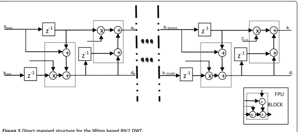
The enhanced architecture for DWT is being proposed in this paper. The main scheme of this architecture al-lows the computation components to achieve precise outputs. Figure 5 shows the architecture proposed for the DWT structure, in which the modified computation
Figure 6Direct mapped 2-D DWT structure.
phenomena adopts a log-based floating point unit to endow a good reduction in power and area, while compromising in speed. The B9/7 2-D DWT is computed in row-column fashion, i.e., row processing is carried out first, followed by column processing. The image, which is initially stored in the external memory, is read into the image processing core in row-by-row order. The row processor performs horizon-tal filtering to the rows, which consists of six computing modules given in Equations 8 to 13 and writes the resultant approximation a1 and detail d1 coefficients to the local memory. Once a sufficient number of rows have been proc-essed, the column processor starts vertical filtering which consists of the same six computing modules. It fetches the approximation coefficients as the inputs from the local memory and generates four subbands:a1a1,a1d1,d1a1, and
d1d1. These four subbands are written back to the external memory in row-wise order. Multiple-level decomposition
is performed on this architecture in non-interleaved fashion, and results between levels are stored in the ex-ternal memory. For the higher levels, an approximation subband is read from the external memory and four higher level subbands are generated using the same computing modules. This operation continues until the desired levels of wavelet decomposition are finished, as shown in Figure 6. As the real-time image processing core requires high performance, we adopt a highly pipe-lined, log-based FPU for implementing the lifting steps.
Log-based floating point unit
This paper utilizes IEEE754 standard format for repre-senting floating point numerals, where a real numberX is divided into three parts as 1 sign bit (s), 8 exponent bits (E), and 23 mantissa bits (m). This is represented as
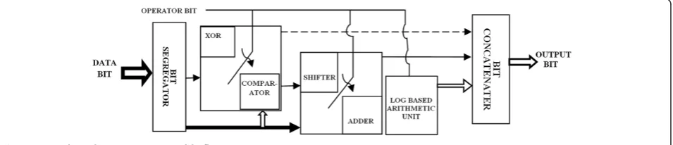
Figure 8Log-based arithmetic circuit model.
X¼ð Þ−1 s1:m2E−127;0≤m≤1 ð15Þ
This demands three different computation procedures. Hence, the log-based arithmetic model that has to append with B9/7 DWT structure is slightly altered to suit the IEEE754 standard as shown in Figure 7. A bit segregator takes the input fed in standard format and separates it into three individual pieces of data. The sign bit of the input is operated with either an Ex-or or comparator module based on the module activated by the operator switch. Similarly, the exponent bits are manipulated with either the operator switch-activated bit shifting module or the adder module. The log-based arithmetic unit performs the floating point computations as shown in Figure 8.
The log-based arithmetic unit embedded in the de-signed FPU utilizes the carry save adder for computing all arithmetic operations. It uses simple log principles, along with operational switches, to select the inputs based on the operation needs. If the adder operator is fed to the switch, the addition computation phenomenon is carried out by merely adding or subtracting the mantissa bits according to the exponent and sign bits. The difference of the two exponents is calculated. If any, perform the
mantissa shift and set the larger exponent as the tentative exponent of the result. Shift the mantissa of the smaller exponent to the right by the difference in the exponents. According to the sign bit, perform addition (if equal) or subtraction (if unequal) on the mantissas to get the tenta-tive mantissa as the result. Normalize and round off the mantissa result. If there is an overflow due to rounding, shift right and increment the exponent by 1 bit. Have the highest of the sign bits be the sign bit of the result. Simi-larly, a multiplication computation procedure is chosen for multiplier input that is fed to the operator switch. The overall data path involved in the multiplier component of this FPU architecture gets simplified. This is a mere com-putation with only mapping involved. Hence, this simplifies the overall stages involved in multiplications. The mantissas of the input data are mapped to the corresponding loga-rithmic number in the LUT. This is followed by adding the logarithms. If any overflow shifts the result to the right, then map with antilogarithm LUT to obtain the mantissa of the result. The exponent of the result is ob-tained by mere addition of the exponent bits, and the sign bit of the result is obtained by the Ex-or-ing both sign bits.
Figure 10Block-based parallel-pipelined SPIHT.
Table 1 PSNR values for different decomposition levels
Images CR PSNR value for different decomposition levels
1 2 3 4 5 6 7 8
Lena 0.2 6.6086 10.0639 13.9454 21.9417 25.0162 23.8757 13.8499 7.8100
0.6 10.7395 15.2456 22.5876 29.7732 31.2794 26.8079 14.0972 7.8751
0.8 10.7395 15.2456 25.7146 32.1411 33.5822 27.3527 14.1218 7.8796
1 10.7395 19.2277 28.5985 34.1943 35.3906 27.6906 14.1390 7.8837
Woman 0.2 6.3568 9.9488 14.1874 19.1769 20.7100 20.3191 12.1483 8.0200
0.6 10.3732 15.0825 19.5321 23.7927 24.8295 23.2527 12.4849 8.1484
0.8 10.3732 15.0825 21.4108 25.2709 25.9779 23.8922 12.5394 8.1693
1 10.3732 17.8149 23.0358 26.2344 26.7792 24.3555 12.5718 8.1816
Mandrill 0.2 5.3449 9.6256 13.6566 19.0756 20.1384 19.8964 12.7907 6.3448
0.6 10.0327 14.5846 19.2745 21.7600 22.3938 21.8662 13.0871 6.4114
0.8 10.0327 14.5846 20.4391 22.8376 23.5433 22.8538 13.1886 6.4328
(a) Original “Lena” Image 0.4bpp PSNR = 28.7759 0.8bpp PSNR = 33.5822
(b) Original “Woman” Image 0.6bpp PSNR = 24.8295 0.9bpp PSNR = 26.4159
(c) Original “Mandrill” Image 0.2bpp PSNR = 20.1384 2bpp PSNR = 29.1360
Figure 11Reconstructed images obtained from different bits per pixel for (a) Lena, (b) Woman, and (c) Mandrill.
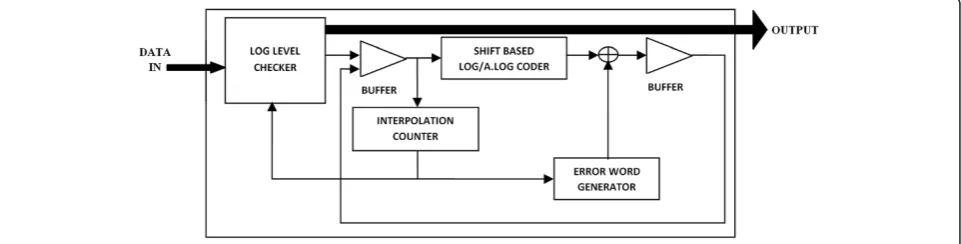
As multiplication in this unit is realized with adders using logarithmic number systems (LNS), log coders play an important role in the design. The design of the log and antilog coder has been adopted from the Paul et al. [23] and is designed with slight modifications in interpolator design as shown in Figure 9. This shows a simple shift-based bit coder network. As the log word generated for the input directly related to the accuracy in the output, different levels of log coders were de-signed. These log coders are classified into six levels, namely 6, 9, 12, 15, 18, and 21 level based on the width of the log words generated. From this, an optimum log coder is chosen by implementing and testing all levels of log coders for best accuracy and minimum area utilization. As the antilog decoder is also designed with a similar struc-ture, most of the log utilized area can be reconfigured for the antilog decoder design. This in turn achieves a good area reduction and makes the proposed model best suited for embedding this FPU in DWT structure.
3.2 Block-based parallel-pipelined SPIHT
SPIHT is a widely used compression algorithm for wavelet-transformed images. To reduce the complexity of SPIHT, an entire picture is decomposed into 4× 4 sets, and the
significance of the union of each 4 × 4 set and its descen-dants is tested. The SPIHT algorithm encodes wavelet co-efficients bit plane by bit plane from the most significant bit plane to the least significant bit plane. The algorithm consists of three passes: insignificant set pass (ISP), insignificant pixel pass (IPP), and significant pixel pass (SPP). According to the results of the (n+ 1) th bit plane, the nth bit of pixels are categorized and processed by one of the three passes. Insignificant pixels classified by the (n+ 1)th bit plane are encoded by IPP, whereas significant pixels are processed by SPP. The main goal of each pass is the generation of an appro-priate bit stream according to the wavelet coefficient in-formation. If a set in this pass is classified as a significant set in thenth bit plane, it is decomposed into smaller sets until the smaller sets become insignificant or they corres-pond to single pixels. If the smaller sets are insignificant, they are handled by ISP. If the smaller sets correspond to single pixels, they are handled by either IPP or SPP, de-pending on their significance.
In the original SPIHT algorithm, three linked lists are maintained for processing the ISP, IPP, and SPP. In each pass, the entries in the linked list are processed in the first-in first-out (FIFO) order. This FIFO order creates a
16 36.85% 29.13% 18.95% 9.58% 5.18% 2.68% 2.03%
15 35.03% 11.16% 7.58% 5.91% 2.86% 1.98% 1.06%
13 33.26% 8.19% 5.39% 3.32% 1.86% 0.93% 0.58%
11 31.68% 5.11% 2.68% 2.53% 1.03% 0.49% 0.26%
Table 3 Output bit error rate computation
Number of output bits
Average bit change error (for 215test sets)
Wallace tree multiplier
Logarithm based multiplier
Logarithm word size in bits
6 bits 9 bits 12 bits 15 bits 18 bits 21 bits
22 12.56 18.56 15.78 14.08 9.58 3.56 1.89
20 11.87 16.59 13.86 11.18 7.38 1.95 0.76
18 11.85 13.48 11.85 9.87 3.85 0.78 0.54
16 11.34 10.56 10.03 7.65 0.96 0.53 0.02
15 10.93 10.06 9.53 4.86 0.08 0.12 0.0085
13 10.58 8.85 7.96 2.95 0.03 0.0085 0.0053
large overhead, which slows down the computation speed of the SPIHT algorithm. To speed up the algorithm, sets and pixels are visited in the Morton order as shown in Figure 2b and processed by the appropriate pass. This modified algorithm, called Morton order SPIHT, is rela-tively easy to implement in hardware with a slight degrad-ation of the compression efficiency when compared with the original SPIHT.
The block diagram of the block-based parallel-pipelined SPIHT architecture is shown in Figure 10. The 8 × 8 block discrete wavelet transformed image is given as the input and sliced into eight planes. The most significant bit (MSB) plane is given to the insignificant pixel pass in the first clock cycle, which finds the significance of each macro and minor block. In the second clock cycle, the insignificant bit planes are given for sorting. The sorting pass updates the insigni-ficant sorting pass. Using the significance bit stream from the insignificant sorting pass, the refining pass (RP) codes the significant micro blocks and gives the coded output. When all the blocks in the 8 × 8 coefficient become signifi-cant, then the controller block stops the sorting pass (SP) and, hence, the unnecessary updating of insignificant sort-ing passes are removed. Thus, pipeline ISP along with par-allel RP and SP increases the throughput.
4 Experiment results and analysis
The overall performance of the proposed image process-ing system is analyzed in this section. As DWT has a wide range of applications in various fields, the proposed system utilizes its efficiency for enhanced image handling and offers good improvement in speed and area consump-tion. Moreover, the accuracy of the output is also dealt with by modifying the computation parts in the DWT structure. This utilizes logarithmic principle and, hence, yields a good reduction in power. Furthermore, at each level of DWT, precision also depends on decomposition at that stage. Hence, it is necessary to select an optimized level of DWT. During the experimentation of this
proposal, the optimized level of DWT is selected based on performance parameters such as peak signal-to-noise ratio (PSNR), compression ratio (CR), and wavelet decomposition computation complexity. The architec-ture is first verified using Matlab for the image parame-ters and then implemented in hardware to analyze its hardware efficiency.
4.1 Image parameters analysis
The goal is to design an optimized DWT structure with floating point computation units. Hence, an efficient level of DWT has to be chosen for modeling in terms of performance parameters. This is done by various image analyses on the standard images obtained from a public image bank [36]. These are 256 × 256 and 8 bits per pixel (8bpp) bitmap images that can be grouped into three image types. Lena and Cameraman are low-frequency (LF) images, Woman and Parrots are medium-frequency (MF) images, and Mandrill and Satellite are high-frequency (HF) images. The frequency type of the image is decided based on the percentage of total image energy (96% to 100% LF, 92% to 96% MF, and≤92% HF) in the aa sub-band obtained after one level of decomposition. To evalu-ate the performance of the proposed architecture, each image was decomposed into different levels with the B9/7 wavelet transform and the transform coefficients were coded using SPIHT algorithm with different compression ratios. The reconstructed image was compared with the original image, and the PSNR values were computed using Equation 16 and are presented in Table 1 and Figure 11.
PSNR¼10 log10 255
2
E2ms
dB ð16Þ
where 255 is the maximal gray level of the original image and E2ms is the sample mean squared error as follows:
E2ms¼ 1 N2
XN
i¼0
XN
j¼0
X ið Þ;j −Y ið Þ;j
ð Þ2 ð
17Þ
whereX(i,j) represents the original N × N image andY (i,j) represents the reconstructed image.
From Table 1, it is clearly observed that the five-level DWT attains a higher PSNR value irrespective of com-pression ratios than all other levels. The next stage of DWT leads to SPIHT coding, which requires a higher level of decomposition. This also supports the selection of five-level decomposition as a generalized case. From Figure 12, it is clearly seen that DWT with five-level compositions attain a good PSNR value; hence, it is de-signed and implemented in hardware using Verilog HDL and synthesized in Xilinx and Altera FPGAs to verify its device-level performance, based on VLSI parameters.
4.2 Numerical accuracy analysis
This work is also concerned with precisions, which is the most important factor of this design. As B9/7 DWT structure utilizes floating point coefficients, accuracy in the result mainly depends on the fractional computational values. Hence, the results obtained with normal integer computation units in DWT suffer from poor accuracy. Moreover, the addition of floating point operation units increases the accuracy. On the other hand, it also in-creases area and delay overhead. Hence, a logarithm-based FPU is integrated along with the DWT structure to achieve a good reduction in area with a higher improve-ment in accuracy. As the whole model depends on the log values, the accuracy of the log values is directly related to the accuracy of the result. Furthermore, as std. single
the std. IEEE754 format. As the product has to be rounded off, there may be some losses in the results. Thus, occurred error during the round off can be pre-dicted from ‘round off error bounds analysis’ done by Paliouras et al. [24]. This study found that the error bounds will be directly depended on the mantissa and not on the operations. This is represented as
Error;∈¼2−t−1 ð18Þ where,tis the number of mantissa bits.
Whenever the floating point is rounded off, it results in a steady loss of data. However, in the case of LNS im-plementation, the obtained product result will only be one bit more than multiplicands. Hence, as rounding off error gets reduced, the error bound only depends on the mantissa bits. The numerical computations are much more complex when involving 47 bit levels, so it is hard to tabulate the actual results. Hence, deviations in the result with respect to the average round off error bounds for the standard test multiplications on the mantissa bits are tab-ulated. In Tables 2 and 3, the accuracies of both the de-signed and existing Wallace tree multipliers are shown. Table 2 gives the percentage of output error generated for the set of input test vectors. It shows how far the models deviate from the actual results. As the product result of the Wallace multiplier has to round off from 64 to 32 bits, most of the significant values in the result are suppressed. On the other hand, the results from the added log trans-formation only offer 33bits, including a carry bit. Though the log conversion and reconversion produces a few er-rors, the proposed model outrates the existing integer-styled FPUs. Hence, from these detailed comparisons, the proposed structure claims an accuracy improvement of 71% over the existing Wallace-based FPUs.
The generated data presented in Figure 13 shows that the accuracy of the Wallace multiplier is linearly dependent on the bit sizes, whereas the accuracy of the log-based multiplier increases exponentially with the input bit size. Table 3 further displays the bit-level accuracy of both cases, showing the percentage of corrupted bits in the results including both‘0 s’as‘1 s’and‘1 s’as‘0 s’. This clearly visualizes the bit performance of both models. Though the bit error form the Wallace seems maintained irrespective of bits, columns 2 and 4 clearly Table 5 Performance comparisons of different SPIHT
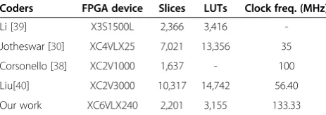
coders on FPGA devices
Coders FPGA device Slices LUTs Clock freq. (MHz)
Li [39] X3S1500L 2,366 3,416
-Jotheswar [30] XC4VLX25 7,021 13,356 35
Corsonello [38] XC2V1000 1,637 - 100
Liu[40] XC2V3000 10,317 14,742 56.40
Our work XC6VLX240 2,201 3,155 133.33
depicts that the log word of size greater than 12 bits have more accuracy than Wallace tree-based multiplication.
4.3 Hardware analysis
The log-based floating point computation achieves su-perior accuracy when compared with normal floating point arithmetic computation. Hence, the computation unit based on the log principle is appended with the biorthogonal DWT structure, which is then implemented in FPGA to analyze its performance in hardware. The ana-lyses were done in two different FPGA environments to show the versatility of the proposed idea as there was no inbuilt IPs used.
4.3.1 Hardware result analysis based on Xilinx device The hardware performance of integer-based and floating point-based DWT structure was implemented on Xilinx Virtex6 XC6VLX240 device [37]. From Table 4, it can be found that, when compared with integer based DWT, the floating point DWT is more accurate with minimum latency. The report also shows that the floating point-based DWT is highly power-efficient, which is achieved by reducing the signal and operational strength using logarithmic principles. Thus, the designed B9/7 DWT structure with log-based FPUs serves as the best com-petitor for integer-based DWT with accuracy improve-ment, along with 47% reduced power and 28% improved delay with optimal area consumption. For comparisons, Table 5 lists the results of different SPIHT image
compression systems based on FPGA devices [30], [38-40]. From the experimental results, the proposed image processing has lesser area utilization, with max-imum clock frequency of 133.33 MHz.
4.3.2 Hardware result analysis based on Altera device To obtain more realistic results, the proposed image pro-cessing core on the Altera® DE2-115 board [41] was used. This comprises of inbuilt support for external memories and the video graphics array (VGA) interface intellectual property (IP) to hold and display large-sized images of up to 2 MB. The Quartus II 10.2 has been used to map the de-sign to Altera cyclone IV EP4CE115F29C7 FPGA, and the results are reported in Table 6. The core is designed like the specific sync signals that are activated using corres-ponding signals, which are controlled by external pins in the board. Five different combinations are used to generate the sync signals, as shown in Table 7. The system is first ini-tialized using Rst button. Then, by M_cntrl low switch, the input images are loaded from the flash. A LED is assigned to indicate the completion of sequential transferring of the image to the inbuilt RAM. Once the inbuilt memory is loaded, a five-level DWT is activated by enabling the D_ac-tive switch and a red light-emitting diode (LED) is assigned to indicate the completion of the process. Once this process has finished, the R/W sync is activated automatically and enables the SPIHT. Similarly, the inverse process is done using ID_active switch, which invokes inverse SPIHT core and IDWT cores. Then, a green LED is used to indicate the Table 6 Altera level analysis
Cores Parameters Altera family and devices
Cyclone Cyclone II Cyclone III Cyclone IV E
EP1C12Q240C6 EP2C70F896I8 EP3C10F256C6 EP4CE115F29C7
DWT Combinational functions 2,893 2,688 2,688 2,688
Logic registers N/A 235 235 235
Memory (bits) 71,445 71,445 71,445 71,445
Fmax(MHz) 71.8 58.58 475.29 1,210.65
DWT with BPS Combinational functions 4,114 4,072 4071 4,071
Logic registers N/A 791 791 791
Memory (bits) 163,840 163,840 163,840 163,840
Fmax(MHz) 71.8 58.58 475.29 1,210.65
Table 7 Sync signal specification
Signals Values
‘0’ ‘1’
Rst Normal mode Resets and Initialize memory
M_cntrl Sync to Address controller Sync to R/W control
D_active Resets DWT-SPIHT and switch to Input mode Activates DWT. Sequentially control R/W sync and initiates SPIHT
ID_active Resets IDWT-ISPIHT and switch to input mode Activates ISPIHT. Sequentially control R/W sync and initiates IDWT
to enable the VGA, and the reconstructed image is shown in VGA display unit.
To compare with the reported architecture presented in [4] and [11,12], the proposed architecture was also tested on Stratix EP1S25B672C7 FPGA. The experimental re-sults which are summarized in Table 8 shows that the number of combinational functions, logic registers, and memories in the proposed architecture is reduced by 24%, 90%, and 12.78% respectively, when compared with the Tian architecture [12]. Furthermore, from Table 6, it is clearly shown that the design is most ominous for all kinds of designs as it does not use the internal IP cores of FPGAs and is designed to acquire optimization. The speed of the system is increased in all successive families as the optimization is increased in each new device. This shows that the system can be adopted in any environment and is best suited for the portable image devices such as mobile phones and digital cameras.
5 Conclusions
This paper has proposed an enhanced image processing system utilizing DWT structure with log-based floating point computation units and SPIHT coders. Hence, effi-cient decomposition levels of DWT and SPIHT algorithms have to be chosen for the hardware implementation. From the detailed analysis performed with various test images, it is found that the five-level decompositions in DWT and block-based parallel-pipelined SPIHT give a good PSNR value irrespective of the compression ratio. This paper adopted a modified arithmetic unit in the DWT structure to achieve good accuracy with minimum latency and power. The modification is stated for the computation units in the DWT structure which are merely integer-styled operation units. As floating point operations are much more complex than integer-based operations, the complexity of the computation hardware also increases. This results in the degradation of the efficiency of DWT operations. Hence, this paper introduced a log-based computation structure to minimize the strength of the operations. Furthermore, it is also found from the re-sults that the accuracy of DWT gets increased as the rounding off errors are fewer with log transformations. The overall structure got 25% improvement in accuracy with the proposed log-based FPUs. In addition, the utilization of LNS in the model provides 47% power
and strength is reduced. Hence, the proposed structure features high speed, good accuracy, and low-power utilization. Thus, the adaptation of this structure in the proposed image processing system results in good hard-ware optimization. Moreover, the model was tested in different environments to test its robustness and versa-tility. This was done by implementing the model in dif-ferent FPGAs. This shows that the model is best suited for portable image analyzing gadgets.
Competing interests
The authors declare that they have no competing interests.
Received: 21 March 2014 Accepted: 4 July 2014 Published: 21 July 2014
References
1. W Sweldens, The lifting scheme: a custom-design construction of biorthogonal wavelets. Appl. Comput. Harmon. Anal.3(2), 186–200 (1996) 2. I Daubechies, W Sweldens, Factoring wavelet transforms into lifting
schemes. J. Fourier Anal. Appl.4(3), 247–269 (1998)
3. T Acharya, C Chakrabarti, A survey on lifting-based discrete wavelet transform architectures. J. VLSI Signal Process.42, 321–339 (2006) 4. S Barua, JE Carletta, KA Kotteri, AE Bell, An efficient architecture for l
ifting-based two-dimensional discrete wavelet transforms. Integr. VLSI J.
38(3), 341–352 (2005)
5. K Andra, C Chakrabarti, T Acharya, A VLSI architecture for lifting-based forward and inverse wavelet transform. IEEE Trans. Signal Process
50(4), 966–977 (2002)
6. G Shi, W Liu, L Zhang, F Li, An efficient folded architecture for lifting-based discrete wavelet transform. IEEE Trans. Circuits Syst.-II56(4), 290–294 (2009) 7. CT Huang, PC Tseng, LG Chen, Flipping structure: an efficient VLSI
architecture of lifting based discrete wavelet transform. IEEE Trans. Signal Process.52(4), 1080–1088 (2004)
8. J Kim, T Park, High performance VLSI architecture of 2D discrete wavelet transform with scalable lattice structure. World Acad. Sci. Eng. Technol.
54, 591–596 (2009)
9. W Jiang, A Ortega, Lifting factorization-based discrete wavelet transform architecture design. IEEE Trans. Circuits Syst Video Technol.11(5), 651–657 (2001)
10. W Zhang, Z Jiang, Z Gao, Y Liu, An efficient VLSI architecture for lifting-based discrete wavelet transform. IEEE Trans. Circuits Syst.–II59(3), 158–162 (2012) 11. C Cheng, KK Parhi, High-speed VLSI implement of 2-D discrete wavelet
transform. IEEE Trans. Signal Process.56(1), 393–403 (2008) 12. X Tian, L Wu, YH Tan, JW Tian, Efficient multi-input/multi-output VLSI
architecture for two-dimensional lifting-based discrete wavelet transform. IEEE Trans. Comput.60(8), 1207–1211 (2011)
13. BF Wu, YQ Hu, An efficient VLSI implementation of the discrete wavelet transforms using embedded instruction codes for symmetric filters. IEEE Trans. Circuits Syst. Video Technol.13(9), 936–943 (2003) 14. C Zhang, C Wang, MO Ahmad, A pipeline VLSI architecture for fast
computation of the 2-D discrete wavelet transform. IEEE Trans. Circuits Syst.–I59(8), 1775–1785 (2012)
16. DU Lee, LW Kim, JD Villasenor, Precision-aware self-quantizing hardware architecture for the discrete wavelet transform. IEEE Trans. Image Process.
21(2), 768–777 (2012)
17. MJ Beauchamp, S Hauck, KD Underwood, KS Hemmert, Architectural modification to enhance the floating-point performance of FPGAs. IEEE Trans. Very Large Scale Integer (VLSI) Syst.16(2), 177–187 (2008) 18. CH Ho, CW Yu, PHW Leong, W Luk, SJE Wilton, Floating-point FPGA:
architecture and modeling. IEEE Trans. Very Large Scale Integer (VLSI) Syst.
17(12), 1709–1718 (2009)
19. G Even, SM Mueller, P-M Seidel, A dual precision IEEE floating-point multiplier. Integr. VLSI J.29(2), 167–180 (2000)
20. CW Yu, AM Smith, W Luk, PHW Leong, SJE Wilton, Optimizing floating point units in Hybrid FPGAs. IEEE Trans. Very Large Scale Integer (VLSI) Syst.
20(7), 45–65 (2012)
21. YJ Chong, S Parameswaran, Configurable multimode embedded floating-point units for FPGAs. IEEE Trans. Very Large Scale Integer (VLSI) Syst.
19(11), 2033–2044 (2011)
22. TH Anand, D Vaithiyanathan, R Seshasayanan, Optimized architecture for floating point computation unit, inInt. conf. on emerging trends in VLSI, embedded sys., nano elec. and tele. sys(Thiruvannamalai, India, 2013), pp. 1–5 23. S Paul, N Jayakumar, SP Khatri, A fast hardware approach for approximate,
efficient logarithm and antilogarithm computations. IEEE Trans. Very Large Scale Integer (VLSI) Syst.17(2), 269–277 (2009)
24. V Paliouras, K Karagianni, T Stouraitis, Error bounds for floating-point polynomial interpolators. IEE Electron. Lett.35(3), 195–197 (1999) 25. IEEE standard for floating-point arithmetic, IEEE Std754-2008(IEEE Inc, New
York, NY, USA, 2008), pp. 1–70. doi:10.1109/IEEESTD.2008.4610935 26. D Vaithiyanathan, R Seshasayanan, High speed low power DWT structure
with log based FPU in FPGAs, inInternational conference on green computing, communication and conservation of energy (ICGCE 2013)
(Chennai, India, 2013), pp. 308–313. doi:10.1109/ICGCE.2013.6823451 27. A Said, WA Pearlman, A new fast and efficient image codec based on set
partitioning in hierarchical trees. IEEE Trans. Circuits Syst. Video Technol.
6(3), 243–250 (1996)
28. FW Wheeler, WA Pearlman, SPHIT image compression without lists, inIEEE international conference on acoustics, speech, and signal processing (ICASSP), vol. 4, 2000, pp. 2047–2050
29. P Corsonello, S Perri, G Staino, M Lanuzza, G Cocorullo, Low bit rate image compression core for onboard space applications. IEEE Trans. Circuits Syst. Video Technol.16(1), 114–128 (2006)
30. J Jyotheswar, S Mahapatra, Efficient FPGA implementation of DWT and modified SPIHT for lossless image compression. J. Syst. Arch.53, 369–378 (2007) 31. CC Cheng, PC Tseng, LG Chen, Multimode embedded compression codec
engine for power-aware video coding system. IEEE Trans. Circuits Syst Video Technol19(2), 141–150 (2009)
32. T Fry, S Hauck, SPIHT image compression on FPGAs. IEEE Trans. Circuits Syst. Video Technol.15(9), 1138–1147 (2005)
33. Y Jin, HJ Lee, A Block-Based, Pass-parallel SPIHT algorithm. IEEE Trans. Circuits Syst. Video Technol.22(7), 1064–1075 (2012)
34. ND Zervas, GP Anagnostopoulos, V Spiliotopoulos, Y Andrepoulos, CE Goutis, Evaluation of design alternatives for the 2D-discrete wavelet transform. IEEE Trans. Circuits Syst. Video. Technol.11, 1246–1262 (2001) 35. C Zhang, Y Long, F Kurdahi, A hierarchical pipelining architecture and FPGA
implementation for lifting-based 2-D DWT. J. Real-Time Image Proc.
2, 281–291 (2007)
36. The USC-SIPI image database Univ. Southern California, signal and Inage processing inst, 2011. Available: http://sipi.usc.edu/database/
37. Virtex-6 FPGA data sheet(Xilinx, Inc, San Jose, CA, USA, 2012). http://www.xilinx. com/support/documentation/data_sheets/ds150.pdf. Accessed 18 Feb 2013 38. P Corsonello, S Perri, P Zicari, G Cocorullob, Microprocessor-based FPGA implementation of SPIHT image compression system. Microprocessor and Microsystems29(6), 299–305 (2005)
39. LW Chew, WC Chia, L-M Ang, KP Seng, Very low-memory wavelet compression architecture using strip-based processing for implementation in wireless sensor networks. EURASIP J. Embed. Syst (2009)
40. K Liu, E Belyaev, J Guo, VLSI architecture of arithmetic coder used in SPIHT. IEEE Trans. Very Large Scale Integer (VLSI) Syst.20(4), 697–710 (2012) 41. DE2-115 FPGA board data sheet(Altera Corporation, San Jose, California,
USA, 2010). ftp://ftp.altera.com/up/pub/Altera_Material/12.1/Boards/DE2-115/DE2_115_User_Manual.pdf. Accessed 15 March 2013
doi:10.1186/1687-5281-2014-37
Cite this article as:Dhandapani and Ramachandran:Power-optimized log-based image processing system.EURASIP Journal on Image and Video Processing20142014:37.
Submit your manuscript to a
journal and benefi t from:
7 Convenient online submission
7 Rigorous peer review
7 Immediate publication on acceptance
7 Open access: articles freely available online
7 High visibility within the fi eld
7 Retaining the copyright to your article