Resource Allocation for
Heterogeneous Wireless Networks
by
Amila Pradeep Kumara Tharaperiya Gamage
A thesis
presented to the University of Waterloo in fulfillment of the
thesis requirement for the degree of Doctor of Philosophy
in
Electrical and Computer Engineering
Author’s Declaration
I hereby declare that I am the sole author of this thesis. This is a true copy of the thesis, including any required final revisions, as accepted by my examiners.
Abstract
Demand for high volumes of mobile data traffic with better quality-of-service (QoS) support and seamless network coverage is ever increasing, due to growth of the number of smart mobile devices and the applications that run on these devices. Also, most of these high volumes of data traffic demanding areas are covered by heterogeneous wireless networks, such as cellular networks and wireless local area networks (WLANs). Therefore, interworking mechanisms can be used in these areas to enhance the network capacity, QoS support and coverage. Interworking enhances network capacity and QoS support by jointly allocating resources of multiple networks and enabling user multi-homing, where multi-homing allows users to simultaneously communicate over multiple networks. It widens network coverage by merging coverage of individual networks. However, there are areas where interworking cannot improve network capacity or QoS support, such as the areas with coverage of only one networks. Therefore, to achieve network-wide uniform capacity and QoS support enhancements, interworking can be integrated with device-to-device (D2D) communication and small cell deployment techniques. One of the challenging issues that need to be solved before these techniques can be applied in practical networks is the efficient resource allocation, as it has a direct impact on the network capacity and QoS support. Therefore, this thesis focuses on studying and developing efficient resource allocation schemes for interworking heterogeneous wireless networks which apply D2D communication and small cell deployment techniques.
First, uplink resource allocation for cellular network and WLAN interworking to pro-vide multi-homing voice and data services is investigated. The main technical challenge, which makes the resource allocation for this system complicated, is that resource allo-cation decisions need to be made capturing multiple physical layer (PHY) and medium access control layer (MAC) technologies of the two networks. This is essential to ensure that the decisions are feasible and can be executed at the lower layers. Thus, the re-source allocation problem is formulated based on PHY and MAC technologies of the two networks. The optimal resource allocation problem is a multiple time-scale Markov de-cision process (MMDP) as the two networks operate at different time-scales, and due to voice and data service requirements. A resource allocation scheme consisting of decision policies for the upper and the lower levels of the MMDP is derived. To reduce the time complexity, a heuristic resource allocation algorithm is also proposed.
WLAN interworking is investigated. Enabling D2D communication within the interwork-ing system further enhances the spectrum efficiency, especially at areas where only one network is available. In addition to the technical challenges encountered in the first inter-working system, interference management and selection of users’ communication modes for multiple networks to maximize hop and reuse gains complicate resource allocation for this system. To address these challenges, a semi-distributed resource allocation scheme that performs mode selection, allocation of WLAN resources, and allocation of cellular network resources in three different time-scales is proposed.
Third, resource allocation for interworking macrocell and hyper-dense small cell net-works is studied. Such system is particularly useful for interference prone and high ca-pacity demanding areas, such as busy streets and city centers, as it uses license frequency bands and provides a high spectrum efficiency through frequency reuse and bringing net-work closer to the users. The key challenge for allocating resources for this system is high complexity of the resource allocation scheme due to requirement to jointly allocate resources for a large number of small cells to manage co-channel interference (CCI) in the system. Further, the resource allocation scheme should minimize the computational bur-den for low-cost small cell base stations (BSs), be able to adapt to time-varying network load conditions, and reduce signaling overhead in the small cell backhauls with limited capacity. To this end, a resource allocation scheme which operates on two time-scales and utilizes cloud computing to determine resource allocation decisions is proposed. Resource allocation decisions are made at the cloud in a slow time-scale, and are further optimized at the BSs in a fast time-scale in order to adapt the decisions to fast varying wireless channel conditions. Achievable throughput and QoS improvements using the proposed resource allocation schemes for all three systems are demonstrated via simulation results. In summary, designing of the proposed resource allocation schemes provides valuable insights on how to efficiently allocate resources considering PHY and MAC technologies of the heterogeneous wireless networks, and how to utilize cloud computing to assist executing a complex resource allocation scheme. Furthermore, it also demonstrates how to operate a resource allocation scheme over multiple time-scales. This is particularly important if the scheme is complex and requires a long time to execute, yet the resource allocation decisions are needed to be made within a short interval.
Acknowledgements
I would like to express my utmost appreciation to my PhD supervisor, Prof. Sherman (Xuemin) Shen, for his exemplary supervision, tremendous support, and valuable advice throughout my PhD program.
I sincerely would like to thank Prof. Weihua Zhuang, Prof. Jon W. Mark, and all my colleagues at the Broadband Communications Research (BBCR) group for the research collaboration, beneficial discussions, and continuous exchange of knowledge.
I gratefully acknowledge my PhD committee members, Prof. Liang-liang Xie, Prof. Oussama Damen, and Prof. Wei-Chau Xie, for their constructive comments and sugges-tions, which helped to improve the quality of the thesis.
I would like to thank Prof. Nandana Rajatheva, Centre for Wireless Communications, University of Oulu and Prof. Poompat Saengudomlert, Center of Research in Optoelec-tronics, Communications and Control Systems, Bangkok University for their valuable comments and suggestions throughout the PhD program. Also, I would like to thank Prof. Tan Ai Hui, Faculty of Engineering, Multimedia University and Dr. Sim Moh Lim, Motorola Solutions, Malaysia for providing supportive recommendation letters at the time of my application for a PhD program at the University of Waterloo.
I would like to express my deepest and heartfelt gratitude to my family and friends for their support and assistance.
Table of Contents
List of Figures xv
List of Tables xvii
List of Abbreviations xix
List of Symbols xxiii
1 Introduction 1
1.1 Interworking of Heterogeneous Wireless Networks . . . 3
1.2 D2D Communication Underlaying Interworking Systems . . . 6
1.3 Interworking of Macrocell and Hyper-Dense Small Cell Networks . . . 8
1.4 Motivations and Thesis Objectives . . . 10
1.5 Thesis Outline . . . 11
2 Implementation of Interworking 13 2.1 Classification of Interworking Architectures . . . 13
2.2 Interworking Architectures . . . 15
2.2.1 Interworking-WLAN (I-WLAN) . . . 15
2.2.2 Generic Access Networks (GAN) . . . 15
2.2.4 IEEE 802.21 Media Independent Handover (MIH) . . . 16
2.3 Summary . . . 17
3 System Model 19 3.1 Network Overview . . . 19
3.2 Cellular Networks . . . 21
3.2.1 User Throughputs via Cellular Networks . . . 21
3.3 WLAN . . . 21
3.3.1 User Throughputs via Contention-Free Channel Access . . . 22
3.3.2 User Throughputs via Contention-Based Channel Access . . . 23
3.3.3 Average User Transmit Power Through Contention-Based Channel Access . . . 24
3.4 Summary . . . 25
4 Resource Allocation for Cellular/WLAN Interworking 27 4.1 Related Work . . . 28
4.2 Cellular/WLAN Interworking System Model . . . 30
4.2.1 Two Time-Scale Resource Allocation Framework . . . 32
4.2.2 Symbols and Notations for the Chapter . . . 32
4.2.3 Traffic Model . . . 33
4.2.4 Channel Model . . . 33
4.2.5 Subcarrier and Contention-Free TXOP allocations, and User Through-puts . . . 34
4.2.6 Power Usage of Multi-homing UEs . . . 34
4.3 MMDP-Based Optimal Resource Allocation . . . 35
4.4 Upper-Level Resource Allocation . . . 39
4.4.1 First Stage Resource Allocation . . . 40 xii
4.4.2 Second Stage Resource Allocation . . . 41
4.5 Lower-Level Resource Allocation . . . 46
4.6 Heuristic Resource Allocation . . . 50
4.7 Simulation Results . . . 53
4.8 Summary . . . 60
5 Resource Allocation for D2D Communication Underlaying Cellular/WLAN Interworking 63 5.1 D2D Communication Underlaying Interworking System Model . . . 64
5.2 Challenges for Resource Allocation and Related Work . . . 65
5.2.1 Challenge 1: Allocation of Resources Capturing Multiple Radio Access Technologies . . . 65
5.2.2 Challenge 2: Efficient Mode Selection . . . 66
5.2.3 Challenge 3: Interference Management . . . 68
5.3 Proposed Three Time-Scale Resource Allocation Scheme . . . 70
5.3.1 First Time-Scale: Mode Selection . . . 73
5.3.2 Second Time-Scale: Joint Resource Allocation for Cellular Network and WLANs . . . 75
5.3.3 Third Time-Scale: Cellular Network Resource Allocation . . . 79
5.4 Implementation of the Proposed Resource Allocation Scheme . . . 79
5.5 Simulation Results . . . 81
5.6 Summary . . . 82
6 Resource Allocation for Interworking Macrocell and Hyper-Dense Small Cell Networks 85 6.1 Related Work . . . 86
6.2 Macrocell and Hyper-Dense Small Cell Interworking System Model . . . 88
6.2.2 Channel Model . . . 90
6.3 Two Time-Scale Resource Allocation . . . 91
6.4 Fast Time-Scale Resource Allocation . . . 92
6.5 Slow Time-Scale Resource Allocation . . . 94
6.5.1 User Allocation . . . 95
6.5.2 Subcarrier Allocation and Water-Level Calculation . . . 95
6.5.3 Implementation of Algorithm 5 . . . 97
6.6 Simulation Results . . . 100
6.7 Summary . . . 104
7 Conclusions and Future Works 105 7.1 Conclusions . . . 105
7.2 Future Works . . . 107
Appendices 109 A 110 A.1 Proof of Convexity of RCB i (PCB) . . . 110
A.2 Proof of Convexity of C4 . . . 111
A.3 Proof of Existence of a Solution for (4.21) . . . 112
A.4 Proof of Convergence of the Iterative Algorithm which Calculates PCB∗ . 112 B 114 B.1 Calculation of Average User Transmit Power . . . 114
B.2 Calculation of Average User Throughputs . . . 117
B.3 Calculation of Normalized Average Interference . . . 119
References 130
List of Figures
1.1 A coverage extension scenario of cellular/WLAN interworking. . . 4 1.2 User-A uses multi-homing capability to simultaneously communicate via
cellular network and WLAN. . . 5 1.3 Traditional and D2D communications in a cellular network. . . 6 1.4 Interworking of macrocell and hyper-dense small cell networks. . . 9 3.1 A network that uses different spectrum efficiency enhancing techniques. . 20 3.2 TXOP allocation in the WLAN. . . 23 4.1 Cellular/WLAN interworking. . . 31 4.2 Resource allocation at slow and fast time-scales. . . 32 4.3 Overview of the MMDP-based two time-scale resource allocation framework. 36 4.4 Throughputs achieved by different algorithms in system-1. . . 56 4.5 Satisfaction index achieved by different algorithms for data traffic in
system-1. . . 57 4.6 Complexities of the different algorithms in system-1. . . 57 4.7 Throughputs achieved by different algorithms in system-2. . . 58 4.8 Satisfaction index achieved by different algorithms for voice traffic in
system-2. . . 59 4.9 Satisfaction index achieved by different algorithms for data traffic in
4.10 Complexities of different algorithms in system-2. . . 60 5.1 D2D communication underlaying cellular/WLAN interworking system. . 65 5.2 Throughputs achieved reusing a RB for a D2D and a traditional link when
the two links are in different proximities and have different channel gains. 69 5.3 Proposed three time-scale resource allocation scheme. . . 72 5.4 Mode selection algorithm. . . 74 5.5 Second time-scale joint resource allocation algorithm. . . 77 5.6 Semi-distributed implementation of the proposed resource allocation scheme. 80 5.7 Throughput performance. . . 83 5.8 QoS satisfaction. . . 83 6.1 A cluster of the interworking macrocell and hyper-dense small cell networks. 89 6.2 Two time-scale resource allocation. . . 92 6.3 Fast time-scale resource allocation within a slot time-scale time slot. . . . 93 6.4 Throughput performance of the proposed and the benchmark schemes. . 103 6.5 Complexities of the proposed and the benchmark schemes. . . 104
List of Tables
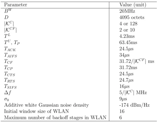
4.1 Simulation Parameters . . . 54 5.1 Average number of required iterations per user . . . 82 6.1 Simulation Parameters . . . 101
List of Abbreviations
3GPP 3rd Generation Partnership Project
AAA Authorization, Authentication and Accounting
ABS Almost Blank Subframes
A-GNSS Assisted Global Navigation Satellite Systems
AP Access Point
ASN Access Service Network
BM1 Benchmark resource allocation algorithm-1
BM2 Benchmark resource allocation algorithm-2
BS Base Station
CCI Co-Channel Interference
CCS Centralized Control Server
CDMA Code Division Multiple Access
CFP Contention-Free Period
CoA Care of Address
CoMP Coordinated Multi-point
CP Contention Period
CSI Channel State Information
CTS Clear To Send
D2D Device-to-Device
DCF Distributed Coordination Function
DL Downlink
DSL Digital Subscribed Line
EAP Extensible Authentication Protocol
EPC Evolved Packet Core
ePDG Evolved Packet Data Gateway
FDD Frequency-Division Duplexing
FFR Fractional Frequency Reuse
FSMC Finite State Markov Channel
GAN Generic Access Networks
GANC Generic Access Networks Controller
HA Home Agent
HCF Hybrid Coordination Function
HM Huristic resource allocation algorithm
ICI Intercarrier Interference
IEEE Institute of Electrical and Electronics Engineers
IP Internet Protocol
IPsec Internet Protocol Security
ISP Internet Service Provider
I-WLAN Interworking-WLAN
L2TP Layer 2 Tunneling Protocol
LPP LTE Positioning Protocol
LTE Long Term Evolution
LTE-A LTE-Advanced
MAC Medium Access Control Layer
MIH Media Independent Handover
MIMO Multipl-Input and Multiple Output
MIP Mobile IP
MIPv6 Mobile IP Version 6
MM Optimal MMDP based resource allocation algorithm
MMDP Multiple time-scale Markov Decision Process
MMSE Minimum Mean Squared Error
MRC Maximal Ratio Combining
NTPv4 Network Time Protocol version 4
OFDM Orthogonal Frequency Division Multiplexing
OFDMA Orthogonal Frequency Division Multiple Access
OTDOA Observed Time Difference Of Arrival
PDG Packet Data Gateway
PDN Packet Data Network
PDN-GW PDN Gateway
PHY Physical Layer
PMIP Proxy Mobile IP
QoS Quality of Service
RB Resource Block
RTS Request To Send
SAE System Architecture Evolution
SDT Sum of Discounted Throughputs
S-GW Serving Gateway
SI Satisfaction Index
SINR Signal-to-Interference plus Noise Ratio
SIP Session Initiation Protocol
TDD Time-Division Duplexing
TXOP Transmission Opportunity
UE Users’ Equipment
UL Uplink
UMTS Universal Mobile Telecommunications System
WAG WLAN Access Gateway
WiMAX Worldwide Interoperability for Microwave Access
List of Symbols
AL
u,l Resource allocation decisions made at lower-level at the beginning of the
(u, l)th time slot AU
u Resource allocation decisions made at upper-level at the beginning of the
uth time slot
B Bandwidth of a network
BW Bandwidth of WLAN
C Number of clusters in the network
D Maximum allowed packet size in contention-based channel access dl The distance within which D2D users are allocated orthogonal cellular
network resources
dp Processing time at the cloud
dq Queueing delay at the cloud
dt Transmission delay when access cloud
dT otal Total delay when access cloud
DL Lower-level policy
DU Upper-level policy
E1(·) Exponential integral
Fs Linear polyhedron at sth iteration
h Channel gain
˜
ht Normalized complex channel gain at tth time slot
Hukt |h˜t|2 of uth user over kth subcarrier
Hu
vkt Normalized power gain of the channel over kth subcarrier between
vth user and the BS to whichuth user is connected to, during tth fast time-scale time slot
Ic Maximum CCI received by the eNB
Iuk Normalized average interference to uth user over kth subcarrier
Iukt Normalized interference to uth user over kth subcarrier duringtth fast
time-scale time slot
K Set of subcarriers available for the entire network
KC Set of OFDM subcarriers available in cellular network KCF Set of contention-free TXOPs available in WLAN
KS Number of possible states for each channel
L Number of fast time-scale time slots within one slow time-scale time slot
L A vector consist of Li’s
L0 Number of fast time-scale time slots in T0
Li Duration of a data packet transmitted by the ith user
LU(·) Lagrangian for the problem P2
LU(2)(·) Lagrangian for the problem P3
M(c) Set of macrocells in cth cluster
n Total noise plus interference power
N Number of users in the interworking system
N0 Single sided power spectral density of additive white Gaussian noise
NW Number of users allocated for the contention-based channel access of
WLAN
N(c) Set of small cells in cth cluster
pukt Transmit power of uth user during tth fat time-scale time slot over kth
subcarrier
P A vector consists of Puk’s
PT,i Total average power available for the ith user
Puk Average transmit power of uth user over kth subcarrier during next slow
time-scale time slot
PiC Total transmit power used by ith user for communications over cellular network
PC
i,k Transmit power level of ith user over kth subcarrier
Pavg,iC Average power usage of ith user for cellular network during one time slot in slow time-scale
PC
tot,i,l(·) Total power allocated by the ith user for cellular network during the
(u, l)th time slot
PCB A vector which consists of transmit power levels of users in SCB during contention-based channel access
PCB
−1 A vector which consists of transmit power levels of users in SCB except
the ith user, during contention-based channel access
PiCB Transmit power level of ith user during contention-based channel access PCB
avg,i(·) Average power usage of ith user for contention-based channel access
during one time slot in slow time-scale
Pi,jCF Transmit power level of ith user over jth contention-free TXOP PψUU
0ψ1U Probability of upper level state change from ψ
U
0 toψ1U
PL ψL
0,0ψL1,0
Probability of lower level state change from ψL
0,0 toψL1,0
PψLL(2) u,0ψLu,1
Probability of lower level state change from ψu,L0 toψLu,1 PW
i Total transmit power used by ith user for communications over WLAN
rukt Throughput achieved byuth user during tth fat time-scale time slot over
kth subcarrier rL
i,u,l(·) Throughput achieved by the ith user at the lower-level during (u, l)th
time slot in fast time-scale
rUi,u(·) Throughput achieved by the ith user at the upper-level during uth time slot in slow time-scale
RDmin,i Minimum data rate required for data traffic services of ith user
RV min,i Minimum data rate required for voice traffic services of ith user
Rmin Minimum required data rate
Ruk Average throughput of uth user over kth subcarrier during next slow
time-scale time slot RC
i Throughput achieved by ith user via cellular network
RCi,k(·) Throughput achieved by ith user over kth subcarrier RCB
i (·) Average throughput achieved by ith user via contention-based channel
access
RCi (D) Throughput achieved by ith user via cellular network using D2D mode RCFi,j (·) Throughput achieved by ith user over jth contention-free TXOP RCi (T) Throughput achieved by ith user via cellular network using traditional
RD2D
min,i Minimum data rate required for ith user’s D2D communications
RL
i,u(·) SDT achieved by the ith user at the lower-level over theuth time slot in
slow time-scale
RN Dmin,i Minimum data rate required for ith user’s non-D2D communications RU
i (·) SDT achieved by the ith user at the upper-level
RW
i Throughput achieved by ith user via WLAN
RWi (D) Throughput achieved by ith user via WLAN using D2D mode RWi (T) Throughput achieved by ith user via WLAN using traditional mode
S1 Set of users who are allocated resource during the first step
S2 Set of users who are allocated resource during the second step
SM Set of low-mobility users within WLAN coverage
SN Set of all users
SS Set of all users except the users in SM
SCB Set of users communicate through contention-based channel access SCF Set of users communicate through contention-free channel access
SID Satisfaction index for data traffic
SIV Satisfaction index for voice traffic
SIx,y Satisfaction index achieved by y algorithm for x traffic class
T0 Duration from a beginning of a time slot to the point at which the BSs
send CSI to the cloud
TACK Duration of a acknowledgment in contention-based channel access
TAIF S Duration of arbitration interframe space in contention-based channel
access
Tcoh Coherence time of a wireless channel
TCF Durations of a contention-free TXOP
TCF P Durations of CFP
TCP Durations of CP
TCT S Duration of CTS message in contention-based channel access
TF Duration of a fast time-scale time slot
TP CFP repetition period
TRT S Duration of RTS message in contention-based channel access
TS Duration of a slow time-scale time slot
TSIF S Duration of short interframe space in contention-based channel access
TL Duration of a time slot in fast time-scale
TU Duration of a time slot in slow time-scale U(c) Set of users in cth cluster
U(c)
b Set of users connected to bth cell in cth cluster
VL Number of fast time-scale time slots within a slow time-scale time slot Vs Set of vertices of the linear polyhedron Fs
xuk Auxiliary variables
x A vector consists of xuk’s
Y Percentage of users who can communicate using D2D mode αC
i,k SINR of the channel betweenith user and cellular BS overkth subcarrier
with unit transmit power αW
i SINR of the channel betweenith user and WLAN AP with unit transmit
power
β Discount factor for the lower-level
γ Vector of dual variables corresponding to contention-free TXOP allocation constraints
γj Dual variable corresponds to jth contention-free TXOP allocation
constraint
∆f Bandwidth of a OFDM subcarrier
θ Discount factor for the upper-level
λ Vector of dual variables corresponding to data traffic constraints λi Dual variable corresponds to data traffic constraint of ith user µ Vector of dual variables corresponding to total power constraints µi Dual variable corresponds to total power constraint of ith user
µuk Water level for uth user over kth subcarrier
ξ Vector of dual variables corresponding to voice traffic constraints ξi Dual variable corresponds to voice traffic constraint of ith user
ρ Correlation coefficient
ρC
i,k ρCi,k = 1 ifkth subcarrier is allocated for ith user or ρCi,k = 0 otherwise
ρCF
i,j ρCFi,j = 1 ifjth contention-free TXOP is allocated forith (i∈ SM) user
or ρCFi,j = 0 otherwise
σ0 Duration an empty slot in contention-based channel access
σ2
uk Average normalized power gain of the channel over kth subcarrier
between uth user and the BS to which uth user is connected to (σuvk)2 Average normalized power gain of the channel over kth subcarrier
between vth user and the BS to which uth user is connected to
τ Probability of a user transmits a packet in a randomly chosen time slot during contention-based channel access
ψu,l System state, i.e., {ψuU, ψu,l}L
ψu,lL State of the lower-level during (u, l)th time slot in fast time-scale ψU
u State of the upper-level during uth time slot in slow time-scale
ΨL Set of all the possible states of lower level ΨU Set of all the possible states of upper level
˜
w , w˜t Complex Gaussian random variables
Ω Average of square channel gain
Chapter 1
Introduction
Recent advancements in mobile industry have dramatically increased the number of smart mobile devices, such as smart phones, tablets and PDAs, operating in any geographical region. Furthermore, the number of data hungry applications that run on these de-vices, such as video streaming, YouTube, Google Maps and Facebook, has also been increased. Consequently, the demand for higher data rates with seamless service cover-age and support for various applications’ diverse quality-of-service (QoS) requirements has been increased than ever before. By year 2020, the volume of mobile data traffic that wireless networks should support is expected to be as high as 1000 times of its value in year 2013 [1, 2]. Therefore, to satisfy the future demands of mobile users, it is essential to develop techniques to enhance the network capacity, QoS support and coverage.
The key techniques that can enhance the wireless network capacity, QoS and cov-erage performance are adding more spectrum to the networks, increasing the spectrum efficiency and adding more small cells to the networks. Though adding more spectrum to the networks is the simplest and most straight forward method to increase the network capacity, cellular communication-friendly low-frequency spectrum is a scarce resource. Most of the underutilized spectrum lies in very high frequency ranges, and high fre-quency communication signals travel only a limited distance due to their propagation characteristics. For example, millimeter waves which occupy frequencies between 30GHz and 300GHz are highly susceptible to penetration loss due to their short wave lengths [3, 4]. As a result, they are highly attenuated even by very thin obstacles, such as rain and very thin walls, leaving them only suitable for indoor communications and for small cells. Therefore, it is crucial to efficiently utilize the spectrum available at the lower
fre-quency ranges, such as 800MHz, 1.7GHz and 2.6GHz communications bands, to facilitate long range and robust outdoor communications.
Spectrum efficiency can be enhanced by several techniques, such as interworking of heterogeneous networks, device-to-device (D2D) communication, frequency reuse, and multiple-input and multiple-output (MIMO) communication techniques. Interworking enhances the spectrum efficiency by satisfying the user QoS requirements utilizing re-sources (i.e., frequency and transmit power) available at multiple networks in an effi-cient manner. For that, it jointly allocates resources of multiple networks and enables user multi-homing, where multi-homing allows users to simultaneously communicate over multiple networks. D2D communication allows direct communication among the users in proximity [5]. It achieves high throughputs due to short communication distances between the transmitters and the receivers, and saves network resources as it uses only a single hop communication. In traditional communication, two hops are used; first hop is between the transmitter and the base station (BS), and second hop is between the BS and the receiver. Frequency reuse enhances the spectrum efficiency as it reuses the same frequency multiple times at different cells, increasing the number of transmitted bits per frequency [6, 7]. MIMO techniques, such as beamforming and coordinated multi-point (CoMP), enhance the spectrum efficiency as well as the robustness of communications by exploiting spatial diversity (or antenna diversity) [8].
Adding small cells to a wireless network increases the network performance by bringing the network closer to the users [9]. In small cells, the distance between users and the BS is short. Thus, the wireless channels are strong, and the users are able to receive high throughputs. In addition to that, small cells also increase the frequency reuse in the network, due to deployment of a large number of low-powered small-radius cells.
Furthermore, most of the high volumes of mobile traffic demanding areas are covered by heterogeneous wireless networks. For example, office buildings, airports and hotspots are covered by cellular networks and wireless local area networks (WLANs). Therefore, to enhance the spectrum efficiency to increase network capacity and QoS performance, interworking can be used in these areas. Furthermore, use of interworking in these areas widens the network coverage by merging coverage of individual networks. However, interworking cannot improve the network performance when there is coverage of only one network, e.g., at places such as rural areas and cell edges. This shortcoming would significantly affect the cell edge users, as the available coverage is also very weak. To overcome this shortcoming and achieve network-wide uniform performance improvements,
Chapter 1. Introduction
interworking can be integrated with D2D communication, frequency reuse, and small cell deployment techniques.
Rest of the chapter is organized as follows. Advantages of and challenges for in-terworking of heterogeneous wireless networks are discussed in Section 1.1. Section 1.2 discusses integration of D2D communication with interworking. Section 1.3 discusses interworking of macrocell and hyper-dense small cell networks (i.e., highly dense small cell deployments). Motivations and thesis objectives are presented in Section 1.4, while thesis outline is presented in Section 1.5.
1.1
Interworking of Heterogeneous Wireless Networks
Most of the high data capacity demanding areas, such as office buildings, hotspots and airports, are covered by multiple wireless networks with diverse radio access technologies, such as cellular networks and WLANs. These different networks can be interconnected via interworking mechanisms in order to provide users with better network coverage, higher throughputs and better QoS support [10].
Interworking provides users with a seamless network coverage by merging the cover-ages of individual networks. This is achieved by allowing the users to access the services they need utilizing resources available in multiple networks. A typical coverage extension achieved by cellular/WLAN interworking is demonstrated in Fig. 1.1, where user-A ini-tiates a call using the cellular network, and the call is continued via the WLAN without any interruption as user-A moves away from the cellular BS.
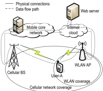
User throughputs and QoS are enhanced as interworking jointly allocates resources of multiple networks, enables user multi-homing, and overcomes the shortcomings of indi-vidual networks. Interworking provides a way to pool the resources available in multiple networks. Jointly allocating these pooled resources among all the users in the interwork-ing system increases the efficiency of resource utilization, compared to individually allo-cating resources available in each network. Multi-homing capability of users’ equipment (UEs) with multiple radio interfaces allows the users to simultaneously communicate over multiple networks, as shown in Fig. 1.2. Thus, UEs can access the services simultane-ously utilizing resources available in multiple networks in an optimal manner. Therefore, multi-homing further improves the efficiency of resource utilization in the interworking
Interworking of Heterogeneous Wireless Networks
Cellular BS
WLAN coverage Cellular network coverage
WLAN AP Internet cloud Mobile core network User-A User-B User-A moves toward WLAN Physical connections Data flow path
(a) User-A moves while calling user-B
WLAN coverage Cellular network coverage
WLAN AP Internet cloud Mobile core network User-B User-A Physical connections Data flow path
(b) When the cellular signal strength becomes weak, user-A continues the call via WLAN Figure 1.1: A coverage extension scenario of cellular/WLAN interworking.
system [11]. Moreover, interworking can overcome the shortcomings of individual net-works, e.g., cellular networks provide services at higher data charges with support for mobility while WLANs provide services at much lower charges with limited support for mobility [12, 13, 14, 15]. Also, interworking can solve one of the WLANs’ inherent prob-lems of significant throughput degradation when a user with a weaker channel or a low transmit power level joining the WLAN, by reallocating that user to another network (e.g., cellular network) in the interworking system [16].
One of the key challenges for interworking is high complexity of the resource alloca-tion schemes for interworking systems, due to existence of multiple physical layer (PHY) and medium access control layer (MAC) technologies within an interworking system. For example, when interworking of Long Term Evolution (LTE) or LTE-Advanced (LTE-A) cellular networks and IEEE 802.11n WLANs is considered, the cellular network has a cen-trally coordinated MAC and a orthogonal frequency division multiple access (OFDMA) based PHY, while the WLAN has a hybrid coordination function (HCF) based MAC and a orthogonal frequency division multiplexing (OFDM) based PHY [13, 14]. The region of feasible transmission rates, which includes all the possible sets of users’ transmission rates that are supportable by the networks considering all the possible resource allocations, depends on the PHY and MAC technologies of different networks in the interworking
Chapter 1. Introduction
Cellular BS
WLAN coverage Cellular network coverage
WLAN AP Mobile core network User-A Internet cloud Physical connections
Data flow path Web server
Figure 1.2: User-A uses multi-homing capability to simultaneously communicate via cellular network and WLAN.
system [17]. Therefore, if resources are allocated to the users without considering the underlying PHY and MAC technologies, the resource allocation decisions may be infea-sible to carry out; hence, efficiency of the interworking system decreases. Thus, resource allocation schemes should be designed capturing diverse PHY and MAC technologies used in different types of networks in the interworking system. Furthermore, resource allocation intervals (i.e., interval between two successive resource allocations) of existing cellular networks are usually shorter than those of existing WLANs [13, 14]. Therefore, the resource allocation schemes for cellular/WLAN interworking should be designed to periodically allocate cellular network and WLAN resources with a shorter and a longer period respectively, where the periods correspond to the resource allocation intervals of the networks. That is, resources of the two networks are allocated at a faster and a slower time-scale, respectively [18]. In addition to that, most of the wireless networks are able to support multiple classes of QoS. For example, cellular networks and IEEE 802.11n WLANs support both constant bit rate voice traffic and variable bit rate data traffic. Therefore, resources of the interworking system should be jointly allocated exploiting multi-homing capability of the UEs to enhance performance of the interworking system.
D2D Communication Underlaying Interworking Systems Cellular BS UE4 UE2 UE1 UE3 Signaling Data+Signaling Traditional communication mode D2D communication mode
Figure 1.3: Traditional and D2D communications in a cellular network.
Furthermore, to achieve optimal uplink user throughputs, the uplink resource alloca-tion schemes should optimally distribute the transmit power available at multi-homing capable UEs among the multiple network interfaces of these UEs [19].
1.2
D2D Communication Underlaying Interworking
Systems
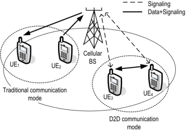
Device-to-device communication allows users in proximity to directly communicate among themselves using direct communication links, without having to send data through a BS. The users who communicate using D2D communication links are referred to as using D2D communication mode, while the users who do not use D2D communication mode (i.e., communications from source to destination are routed through a BS) are referred to as using traditional communication mode. Fig. 1.3 shows a cellular network, where UE1 and UE2 communicate using traditional communication mode while UE3 and UE4
communicate using D2D communication mode.
Enabling D2D communication in an interworking system provides several important benefits. First, an interworking system may not provide the enhanced network
Chapter 1. Introduction
mance at areas such as cell edges or rural areas where only one network is available. D2D communication can be applied in these areas to improve the network performance, as it allows direct communication between source and destination UEs which are in proximity, and incorporates hop and reuse gains to the network [20, 21, 22, 23, 24]. Hop gain is a result of D2D communication links using either uplink (UL) or downlink (DL) resources only. Reuse gain is achieved by simultaneously using the same set of resources for both traditional and D2D communication links [20, 22, 25]. Second, D2D communication re-duces the cost of service as it allows network operators to offload traffic from the mobile core network. Third, enabling D2D communication does not require additional hardware deployments.
Similar to interworking, D2D communication also cannot improve the network per-formance throughout the network, as the probability of communications among users in proximity is small [26]. Therefore, integration of D2D communication and interworking would complement the areas where each of these technologies can improve the network performance; hence, the integrated system would provide uniform performance improve-ments throughout the networks.
D2D communication between two UEs can be initiated by UEs without any involve-ment of the mobile operators, or it can be controlled and initiated by the mobile operator. The latter is called network assisted D2D communication mode. It provides security and mobility support for the UEs, and reduces the interference caused by non-synchronized UEs [22].
There are two types of resource allocations for D2D communication links: 1) a fixed set of resources are allocated for the D2D communication links, and from which resources for each D2D communication link is allocated; and 2) resources for D2D and traditional communication links are jointly allocated. Each of these two resource allocation types can be again divided into two categories based on the nature of the resource sets that are allocated for D2D and traditional communication links. When the same resource set is shared by D2D and traditional communication links, such resource sharing is called non-orthogonal resource sharing. When the allocated resource sets for D2D and tradi-tional communication links are non-overlapping, it is called orthogonal resource sharing. Non-orthogonal resource sharing is more efficient than orthogonal resource sharing, as it allows both D2D and traditional communication links to utilize all the available re-sources. However, use of non-orthogonal resources causes co-channel interference (CCI) among D2D and traditional communication links.
Interworking of Macrocell and Hyper-Dense Small Cell Networks
There are several technical challenges which make the resource allocation for D2D communication underlaying interworking systems complicated: 1) involvement of multi-ple PHY and MAC technologies of different networks [14, 13, 11], 2) selection of users’ communication modes (i.e., traditional or D2D) for multiple networks to maximize hop and reuse gains while considering the resources available in individual networks, and 3) interference management [22].
1.3
Interworking of Macrocell and Hyper-Dense Small
Cell Networks
Small cells can be densely deployed to cater for high service demands in areas, such as busy streets, city centers and shopping malls. They can be deployed by the network op-erators as well as the subscribers, in both planned and unplanned manner [2]. Backhauls to the small cell BSs could be fiber-optic cables or digital subscriber lines (DSL) [27].
There are four main benefits of dense small cell deployments. First, hyper-dense small cell deployments increase the network capacity by bringing network closer to the users [28, 9]. Second, the spectral efficiency is significantly enhanced by reusing the same set of spectrum resources in a large number of small cells [29]. Third, less deployment and operational costs due to low-cost of small cell BSs, DSL based backhauls and that most of the small cell BSs are installed and operated by the subscribers [27]. Fourth, higher carrier frequencies can also be used for small cells due to small targeted coverage areas.
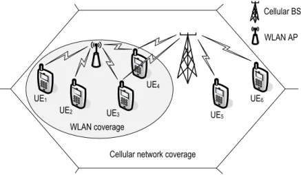
However, there may be coverage holes in hyper-dense small cell networks due to unplanned deployment of small cells with small coverage areas. In addition to that, highly mobile users may experience call drops in these networks, as they have to be frequently handed over from one small cell to another. These two shortcomings can be eliminated by enabling interworking between hyper-dense small cell networks and macrocell networks, as the users at coverage holes of hyper-dense small cell networks and the highly mobile users can be allocated to the macrocell network. Therefore, interworking of macrocell and hyper-dense small cell networks is a promising technique that can enhance the network performance to satisfy the ever increasing demand for high volumes of mobile data traffic. Interworking of macrocell and hyper-dense small cell networks is shown in Fig. 1.4.
Chapter 1. Introduction
Macro cell BS
Small cell BS
Figure 1.4: Interworking of macrocell and hyper-dense small cell networks.
There are several challenges for allocating resources for interworking macrocell and hyper-dense small cell networks. First, such network is prone to severe CCI, mainly due to short distances between the densely deployed small cells and that many small cell BSs are deployed by the subscribers in an unplanned manner [9]. Therefore, resources of all the small cells in vicinity should be jointly allocated such that CCI remains within a tolerable level. Second, network load significantly varies and moves across the network with time. For example, network load will be high near restaurants during lunch time, while it will be high near coffee shops in the afternoon. Thus, variations of the network load should be considered in order to optimally utilize the available spectrum resources. Third, small cell backhaul capacities may be limited due to the use of DSLs. Thus, it may be a bottleneck if the volume of user data and control signaling is high. Fourth, limited computational capacity available at low-cost small cell BSs. Therefore, small cell BSs cannot execute computationally expensive resource allocation algorithms.
In addition to jointly allocating resources of the small cells, CCI can be managed by allocating almost blank subframes (ABS) [30, 31], fractional frequency reuse (FFR) techniques [32, 33], and MIMO techniques, such as beamforming and joint decoding [34, 35, 36, 28]. By allocating ABSs, CCI among the small cells cannot be managed as ABSs are allocated by the macrocells to mitigate CCI between the macrocell and
Motivations and Thesis Objectives
the small cells. The FFR techniques will significantly reduce the frequency reuse in the network due to highly dense small cell deployments. The MIMO techniques are inefficient for managing CCI in a densely deployed small cell network due to three reasons: 1) a dense unplanned small cell deployment causes each cell to receive CCI not only from the neighbouring cells, but also from neighbours of the neighbouring cells; 2) requirement to exchange a large volume of channel state information (CSI) among a large number of BSs in proximity, occupying a large part of the small cells’ limited capacity backhauls, as the MIMO techniques coordinate BSs based on the instantaneous CSI; and 3) high cost of antenna arrays.
1.4
Motivations and Thesis Objectives
Demand for high volumes of mobile data traffic with better QoS support and seamless network coverage is ever increasing. Most of these high volumes of data traffic demanding areas are covered by heterogeneous wireless networks. Therefore, through interworking of these heterogeneous wireless networks, network capacity, QoS support and coverage can be improved. However, interworking cannot improve the network performance when coverage of only one network is available. Thus, to achieve network-wide uniform per-formance improvements, interworking can be integrated with D2D communication, fre-quency reuse, and small cell deployment techniques. There are several challenging issues that need to be solved before these techniques can be applied in practical networks. One of such issues is the efficient resource allocation when these techniques are applied. Effi-ciently allocating resources, such as frequency and transmit power, is crucial as it has a direct impact on the spectrum efficiency. Therefore, in this thesis, we study and develop efficient resource allocation schemes for interworking heterogeneous wireless networks which also apply D2D communication and small cell deployment techniques for different areas of the network.
The objectives of the thesis can be stated as follows:
1. to design an efficient resource allocation scheme for cellular/WLAN interworking system, based on the PHY and MAC technologies and the different resource allo-cation time-scales of the two networks;
Chapter 1. Introduction
2. to present a resource allocation scheme for D2D communication underlaying cellu-lar/WLAN interworking system, to determine effective user communication modes and allocate resources of the two networks; and
3. to develop a resource allocation scheme for interworking macrocell and hyper-dense small cell networks, based on the characteristics of the hyper-dense small cell net-works.
1.5
Thesis Outline
The remainder of the thesis is organized as follows.
Chapter 2describes implementation of interworking of heterogeneous wireless networks.
Chapter 3 presents the system model.
Chapter 4 proposes an optimal multiple time-scale Markov decision process (MMDP) based and a low-complex heuristic resource allocation schemes for cellular/WLAN inter-working system. The resource allocation schemes are designed considering multi-homing capable users with voice and data traffic requirements, two time-scales, and underlying PHY and MAC layer technologies of an OFDMA based cellular network and a WLAN which operates on contention-based and contention-free channel access mechanisms.
Chapter 5first presents the technical challenges for selecting communication modes and allocating resources in a D2D communication underlaying cellular/WLAN interworking system, and discusses existing and new solutions. Second, a semi-distributed resource al-location scheme is proposed to address these challenges, and the related implementation issues are investigated.
Chapter 6 focuses on resource allocation for interworking macrocell and hyper-dense small cell networks. First, it discusses potentials of using cloud computing to assist resource allocation decision making process, to reduce the computational burden for low-cost small cell BSs. Second, a cloud assisted resource allocation scheme which operates on two time-scales is proposed. Two time-scales are used to overcome the negative effect of high delay, when access cloud computing facilities, on the resource allocation decisions.
Chapter 2
Implementation of Interworking
This chapter provides implementation details of interworking of heterogeneous wireless networks. Section 2.1 describes different categories of interworking architectures and the mechanisms that can be used for designing interworking architectures belonging to those categories. Section 2.2 presents the interworking architectures that have been proposed in literature. The chapter is summarized in Section 2.3.
2.1
Classification of Interworking Architectures
Several architectures which enable interworking by interconnecting multiple networks have been proposed in literature. These interworking architectures can be classified into four main categories, based on the supported interworking levels (i.e., service levels). The main interworking levels are as follows [10],
• Level A: Mobile users are only allowed to access the services provided by the visited network.
• Level B: Mobile users are able to access the services provided by its home net-work through the visited netnet-work. However, users have to re-establish the sessions through the visited network.
• Level C: This level provides service continuity when users move between different networks, unlike in level B. Users do not have to re-establish the active sessions.
Classification of Interworking Architectures
However, there may be temporary QoS degradation during the transition time (i.e., handover).
• Level D: This level provides seamless mobility with no QoS degradation during and after the transition.
The key mechanisms (i.e., concepts and technologies) which can be used for achieving different interworking levels can be summarized as follows [10],
• Mechanisms that achieve interworking level A: This mechanism mainly ex-tends the home network’s authorization, authentication and accounting (AAA) functionalities to the visited network. In addition to that, enhanced network dis-covery mechanisms are also employed in order for the mobile users to know the networks which they are allowed to connect (i.e., which network is going to accept its credentials, etc.). E.g., Interworking-WLAN (I-WLAN) architecture [37].
• Mechanisms that achieve interworking level B: Data between the mobile user and its home network is transferred via a layer-2 tunneling protocol (L2TP)/internet protocol security (IPsec) tunnel. E.g., I-WLAN architecture.
• Mechanisms that achieve interworking level C: Service continuity when han-dover occurs is achieved by employing network layer hanhan-dovers with the aid of mo-bile Internet protocol (MIP) or proxy momo-bile Internet protocol (PMIP) techniques [38]. These MIP based mobility solutions have been adopted by the LTE/system architecture evolution (SAE) architecture to provide service continuity between LTE/SAE networks and other networks [37]. The main advantage of using PMIP over MIP is that PMIP does not require a UE to update its new Internet protocol (IP) address (i.e., care of address (CoA)) at the home agent (HA) whenever the UE moves to a new network. In addition to these solutions, if the service is available at both visited and home networks, service continuity can also be achieved using ap-plication based mobility solutions, such as session initiation protocol (SIP), without using network layer handover mechanisms.
• Mechanisms that achieve interworking level D: Seamless handovers between networks with different radio access technologies are achieved by optimizing the network layer and the data link layer handover mechanisms. Three methods can
Chapter 2. Implementation of Interworking
be used for reducing the latency in the network layer during a handover: 1) acquire CoA before the handover occur, using MIP version 6 (MIPv6); 2) pre-authenticate the UE; and 3) preconfigure the network layer parameters in the targeted network prior to handover occur, using context transfer protocols. In the data link layer, latency can be reduced by providing UEs with information about the available net-works, such as, configurations, signal level measurements and resource availability, prior to handover occur. Furthermore, when UEs are capable of multi-homing, UEs can simultaneously connect to two networks; thus, optimization procedures for these two layers are not required. Generic access network (GAN) architecture uses the UE multi-homing capability to support interworking level D [39].
2.2
Interworking Architectures
Several interworking architectures have been proposed in literature. This section de-scribes implementations of I-WLAN, GAN, interworking of worldwide interoperability for microwave access (WiMAX) and 3rd generation partnership project (3GPP) networks, and IEEE 802.21 media independent handover (MIH) architectures.
2.2.1
Interworking-WLAN (I-WLAN)
I-WLAN [37] is commonly referred to as loose coupling interworking, and it can provide levels A and B interworking of WLANs and cellular networks, such as, 3GPP universal mobile telecommunications system (UMTS) networks, for packet services. In this scheme, cellular network extends its AAA functions to the WLAN by exchanging extensible au-thentication protocol (EAP) messages between these two networks. The users can then be authenticated and authorized at the WLAN based on the credentials provided by the cellular network. In the interworking level B, data is transferred between UEs and the packet data gateway (PDG) in home cellular network through secure IPsec tunnels.
2.2.2
Generic Access Networks (GAN)
GAN [39] is referred to as tight coupling interworking, and it supports interworking levels B, C and D for circuit and packet services between cellular networks and other
broad-Interworking Architectures
band access networks, such as, WLANs. In this architecture, GAN controller (GANC) is introduced to the cellular network to connect the cellular network with the other broad-band networks. Access control is done at the cellular network unlike in the I-WLAN architecture. Data is transferred between the UEs and GANC via IPsec tunnels. In-terworking level-D is achieved by using multi-homing capability of the dual-radio UEs. Multi-homing capability is used for simultaneously connecting UEs to cellular network and GANC via WLAN. Therefore, in this architecture, network layer or data link layer handover optimization is not required.
2.2.3
WiMAX and 3GPP Networks Interworking
The first release of WiMAX architecture has incorporated solutions based on the I-WLAN architecture to facilitate interworking between 3GPP cellular networks and WiMAX net-works to support interworking levels A and B. Interworking level C can be achieved between WiMAX and LTE/SAE networks by using MIP and PMIP technologies while interworking level D can be achieved by using multi-homing capability of the UEs. How-ever, achieving interworking level D for single-radio UEs requires sending the handover related information (for handover optimization, resource reservation, access control, etc.) to the target network. These information can be sent to the target network using the tunnels created through the network which currently serves the UE [40]. In the inter-working system consisting of WiMAX and 3GPP networks, 3GPP network extends its AAA functionalities to WiMAX access service network (ASN) gateway to authenticate and authorize 3GPP network users. In this architecture, the MIP client is located at the UE when MIP is used, while it is located at the WiMAX ASN gateway when PMIP is used. HA is located at the packet data network (PDN) gateway in the LTE/SAE network [10].
2.2.4
IEEE 802.21 Media Independent Handover (MIH)
MIH standard [41] has been proposed to provide interworking level D functionalities among IEEE 802 wireless/wired networks (e.g., IEEE 802.11 and 802.16) and cellular networks. MIH standard defines new functionalities to be added to the data link layer of the UEs and the networks. These new functions will check the resource availability in the candidate networks and reserves resources in preparation for the handover. Further, UEs
Chapter 2. Implementation of Interworking
will be updated with the information about the configurations of the reserved resources. However, MIH focuses only on initiation and preparation phases of a handover. It does not provide optimized mechanisms to be followed during the handover process.
2.3
Summary
This chapter describes the four main interworking levels, which are defined based on the QoS during handovers and the services that users are able to access through a visited network. The mechanisms that can be used to achieve those interworking levels are also presented. Finally, implementations of the interworking architectures that have been proposed in literature are described.
Chapter 3
System Model
The system model is described in this chapter. Section 3.1 presents an overview of the system model, while Sections 3.2 and 3.3 provides details of the cellular networks and the WLANs. A summary of the chapter is given in Section 3.4.
3.1
Network Overview
A wireless network that uses interworking, D2D communication and small cell deployment techniques to enhance network throughput, QoS and coverage performance is considered. An example of such network is shown in Fig. 3.1. There are three types of areas of in-terest in this network: 1) areas which are only covered by the macrocell network, 2) areas which are covered by both macrocell network and a WLAN, and 3) areas which are covered by both macrocell and hyper-dense small cell networks. In the example shown in Fig. 3.1, UE3−UE5, UE9 and UE10 are in the first area, and these UEs communicate
only through the macrocell network. The macrocell network and the WLANs are inter-connected using interworking mechanisms. Thus, the UEs in the second area are able communicate through macrocell network or WLAN, or through both networks using the UE multi-homing capability. For example, UE1 communicates only using the WLAN
while UE2 communicates simultaneously using both WLAN and the macrocell network.
Using D2D communication, users in proximity can directly communicate among them-selves, e.g., UE4 and UE5. Moreover, since UE11 and UE12 are within coverage of both
Network Overview Macrocell BS Small cell BS UE3 UE3 UE4 UE1 UE2 UE5 UE4 UE4 UE12 UE11 WLAN AP UE8 UE6 UE7 UE9 UE10
Figure 3.1: A network that uses different spectrum efficiency enhancing techniques.
Chapter 3. System Model
both networks. Macrocell and hyper-dense small cell networks are interconnected us-ing interworkus-ing mechanisms. Therefore, in the third area, UEs can communicate usus-ing either network or both networks. For example, UE6 and UE7 communicate using the
hyper-dense small cell network and the macrocell network, respectively.
Macrocell and hyper-dense small cell networks are OFDMA based networks, similar to LTE and LTE-A networks [14]. WLANs consist of contention-based and contention-free polling based channel access mechanisms, as in IEEE 802.11n WLANs [42].
3.2
Cellular Networks
Macrocell and hyper-dense small cell networks consist of OFDMA based PHY layers. MAC layer of these networks centrally coordinates the allocation of the network resources. Resources to be allocated are OFDMA subcarriers and transmit power of the BSs and UEs. In the uplink resource allocation, only UEs’ transmit power is considered. User allocation is also considered as a part of the resource allocation when multiple cells are considered.
3.2.1
User Throughputs via Cellular Networks
Available frequency band is divided into subcarriers with bandwidth of ∆f. The max-imum achievable error free data rate by the ith user over the kth OFDM subcarrier of the cellular network can be expressed by
RCi,k(Pi,kC) = ∆flog2(1 +αCi,kPi,kC), (3.1)
where αC
i,k is the signal-to-interference plus noise ratio (SINR) of the channel between
cellular BS and the ith user over the kth subcarrier with unit transmitted power; and PC
i,k is the transmit power level of theith user over the kth subcarrier.
3.3
WLAN
The WLANs consist of an OFDM based PHY and a MAC that grants transmission opportunities (TXOP) for the users using two channel access mechanisms:
contention-WLAN
based channel access during contention period (CP) and contention-free polling based channel access during contention-free period (CFP). CP and CFP alternate over time and they repeat once everyTP. Durations of CP and CFP are denoted byTCP andTCF P,
respectively. Operation of these two channel access mechanisms is shown in Fig. 3.2. In the contention-based channel access, users contend for the channel to obtain TXOPs, and each of these TXOPs allows the user who obtained the TXOP to send a data packet of D bits as channel capture is not allowed. Furthermore, four-way handshaking scheme with request-to-send (RTS) and clear-to-send (CTS) messages is used for improving the efficiency of the WLAN by reducing the duration of collisions, and for solving the hidden terminal problem. In the contention-free polling based channel access, users are granted TXOPs using a centralized polling mechanism, and each of these TXOPs is defined as a fixed duration (TCF) which allows users to transmit. Contention-based channel access
is more suitable for variable bit rate data traffic while contention-free channel access is more suitable for constant bit rate voice traffic [43]. Thus, different sets of users can be assigned to these two channel access mechanisms, based on the user requirements.
User throughputs achieved by contention-free channel access mechanism can be de-termined using the Shannon capacity formula, similar to throughput calculation for the cellular network users in Section 3.2.1, due to coordination of TXOP allocation by a centralized polling mechanism. However, in the contention-based channel access, users obtain TXOPs in a random manner. Moreover, data transmissions during an obtained TXOP may not be successful due to collisions of different users’ data packets. Thus, in the resource allocation problem formulation, average user throughputs and average power consumptions of the users who use contention-based channel access are used.
3.3.1
User Throughputs via Contention-Free Channel Access
The maximum achievable error free data rate by theith user using thejth contention-free TXOP can be expressed by
RCFi,j (Pi,jCF) =BW log2(1 +αWi Pi,jCF), (3.2)
whereαW
i is the SINR of the channel between the WLAN access point (AP) and theith
user with unit transmitted power; PCF
i,j is the transmit power level of the ith user over
the jth contention-free TXOP; and BW represents the bandwidth of a WLAN. 22
Chapter 3. System Model CFP,TCFP CP,TCP CFP repetition interval,TP RTS CTS Data ACK Contention-free TXOPs TCF Beacon transmission
Figure 3.2: TXOP allocation in the WLAN.
As wireless channels are assumed to be fixed within their coherence time, resource allocation interval for the WLANs is selected such that it is shorter than the channel coherence time. Therefore, the SINRs (i.e., αW
i ) remain unchanged within a resource
allocation interval. Furthermore, TP is selected such that it is shorter than or equivalent
to the resource allocation interval. Thus, SINR levels are the same for contention-free and contention-based channel access mechanisms.
3.3.2
User Throughputs via Contention-Based Channel Access
Average throughput achieved by the ith of the users who use contention-based channel access during a CP is given by [13, 44]
RCBi (L) = τ(1−τ) NW−1D T1+NWτ(1−τ)NW−1 ∑NW j=1Lj , (3.3)
where T1 can be calculated as:
T1 =NWτ(1−τ)NW−1(TCT S+TACK+ 3TSIF S) + (1−(1−τ)NW)(TRT S+TAIF S)
+ (1−τ)NWσ
0.
In (3.3), Li is the duration of a packet transmitted by the ith of the users who use
WLAN
channel access, and TSIF S, TAIF S, TACK, TRT S, TCT S and σ0 are the durations of short
interframe space, arbitration interframe space, acknowledgment, RTS message, CTS mes-sage and an empty slot, respectively. τ is the probabilities of a user transmits a packet in a randomly chosen time slot, and it can be found by [44].
RCB
i (L) given by (3.3) cannot be used in a resource allocation problem as it is not
in terms of the transmit power levels of the users. Therefore, Li is rewritten in terms
of the throughput that is achieved by theith user during a successful transmission, and substitute it into (3.3) [45]. Then, RCBi (L) can be rewritten as
RCBi (PCB) = τ(1−τ) NW−1D T1+ DNWτ(1−τ) NW−1 BW ∑Nw j=1 1 log2(1+PjCBαWj ) , (3.4)
where PiCB is the transmit power level of the ith user during the CP over the WLAN interface, and PCB is a vector consisting of PCB
i ’s. From (3.4), it can be seen that
RCB
i (PCB) is the same for all the users who use contention-based channel access.
Fur-thermore, RCB
i (PCB) is a concave function when NW is fixed, and the proof of convexity
of RCB
i (PCB) is given in Appendix A.1.
3.3.3
Average User Transmit Power Through Contention-Based
Channel Access
Average power usage of a contention-based channel access user through the WLAN in-terface during a CP can be determined as follows. Since τ(1−τ)NW−1 is the probability of a successful transmission during a CP, the average power usage of the ith of the contention-based channel access users is
Pavg,iCB (PCB) = τ(1−τ)NW−1LiP CB i Tavg TCP TP , (3.5)
where Tavg is the average duration of channel occupancy due to an event of successful
transmission, collision, or empty slot in which no user transmits [44]. After simplifying 24
Chapter 3. System Model
(3.5), Pavg,iCB (P<