International Journal of Innovative Technology and Exploring Engineering (IJITEE) ISSN: 2278-3075,Volume-8 Issue-12, October 2019
Abstract: High rise building structures are highly affected by lateral loads and wind forces. To enhance lateral force outrigger systems are developed, which are one of the most popular and efficient, because they are easier to build and they provides good lateral stiffness. With the rise of building height, deep beam become concrete walls at least of one story height. Axial shortening effect between core and perimeter structure has to be considered.In the present work 20 story reinforced concrete structure has taken with outrigger walls attached from core to the outer perimeter column. By changing the different position of outrigger level are kept for analysis.The building without and with outrigger are compared with bareframe. These are different building models analysed (a) Bare frame of twenty story building (b) Bare frame with core shear wall building (c) Outrigger system at top of building (d) Outrigger system at top & 0.75 Height of building (e) Outrigger system at top & 0.50 Height of building (f) Outrigger system at top & 0.25 Height of building. Non-linear static analysis results were compared. The analytical methods used in the work are pushover method. In this work, various parameters like pushover curve, displacement vs base force, story displacement, hinges formation are obtained for all the models.Outrigger at optimum level at 0.5 Height gives better results in both displacements and base force. To sustain peak lateral loads these systems are provided half of the height. These study gives has inelastic behaviour of structure.
Key words:High Rise Building, Hinges Formation Non-Linear Static Analysis, Outrigger System.
I. INTRODUCTION
Today’s increased in population leads to requirement of high-rise buildings in metropolitan cities. In tall buildings during the occurrence of lateral loads which has higher sway by more slenderness. When building height of structure increases there must be a good lateral load resisting system other than shear walls to avoid from lateral load effect, since the shear walls are up to certain story high. Outrigger systems are one of the best effective system, which are easier to build, cost saving and provide better lateral stiffness. In outrigger braced structures where, central core connects to the outer column, which are efficient structural form. Outriggers are deep, stiff beam which connects exterior columns to core wall to keep the columns in their position in turn reducing the sway, these are stiff arms engaging outer column to central core tries to tilt, outrigger level induces a tension-compression couple in the outer columns acting in
Revised Manuscript Received on October 05, 2019.
D. Arvind kumar, Civil Engineering, Anurag Group of Institutions, JNTUH, Hyderabad, India Email: [email protected]
Dr. A. Vimala, Civil Engineering, Anurag Group of Institutions, JNTUH, Hyderabad, India Email: [email protected]
opposition to that movement acting on the core at that level of outrigger system.
This concept is same as boat, the core in the tall building may be related to the mast of the deliver, the outrigger performing like the spreaders and the exterior columns just like the remains or shroud of the ship.
Outriggers are strong enough to generate above and below the location as restraining moments. The base moment gets lesser by either increasing the number of outrigger levels. It is more efficient for an outrigger system, rather than increasing the numbers with lesser stiffness it’s better to building with strong outrigger wall.
II. OBJECTIVES
The following are the main objectives of the project:
The main objective of the work in the present study to check the behavior of reinforced concrete framed model of without and with outrigger system using ETABS.
The models of different types are analyzed by Non-linear static analyses with a parameter of Base Shear Displacement and formation of plastic hinges in total structure.
To study the lateral behavior of outrigger at different optimum levels of outrigger in total height.
III. MODELLINGOFTHESTRUCTURE
Modelling data and material properties
In this work, six models are considered to understand the behaviour the structure by the applied lateral force. A 20 Storey model of plan dimension 18mx18m consists of building models, building details, loads and load combinations. The characteristic strength of concrete M25 and steel of Fe500 were taken. The 59.5m total height of the building models. From top to bottom all column sizes are same. Non-linear analysis is carried out and results were compared with all the six different models.
Table- 3.1: Models of building in present study BUILDING
MODEL DESCRIPTION
1 Bare frame
2 Core shear wall
3 Outrigger at top of building
4 Outrigger at top and 0.75H of
building
5 Outrigger at top and 0.50H of building
6 Outrigger at top and 0.25H of
building
Performance of Outrigger System by Non-Linear
Static Method
Table- 3.2: Details of modeled building information
Material Data
Plan dimension 18m X 18m
Column size 750mm X 750mm
Beam size 350mm X 600mm
Slab thickness 150mm
Floor to floor height 3m
Base height 2.5m
Grade of concrete M25
Grade of steel Fe500
No of stores 20
No of bays in x-direction 4
No of bays in y-direction 4
Bay width in x-direction 6m
Bay width in y-direction 6m
Live load 3 KN/m2
Wall load 12 KN/m2
Floor finishes 1.5 KN/m2
Shear wall thickness 250mm
Outrigger wall thickness 250mm
Load combinations taken into consideration
Load combinations which are considered as per IS code provision i.e., IS 1893:2002, clauses 6.3.2.1 are as follows: -
1.5(DL + LL)
Process required in Pushover Analysis
The sequence of steps involved in a pushover analysis:
Take a new model
Define all the material and section properties Assign all the properties and loads to the respective
Members Define and assign load combination and load patterns
Design and check whether the all members are passing
Assign all hinges to columns, beams and walls Again, overwrite all hinges assigned members Set the load cases for linear and non-linear Modify the non-linear configurations Run the analysis
Check the results for pushover curve and deformed shapes.
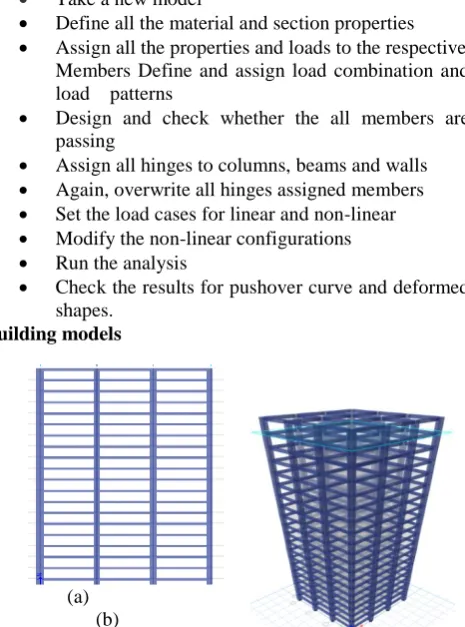
Building models
[image:2.595.309.541.94.232.2]
(a) (b)
Fig. 3.1: Bare frame (a) elevation view (b) 3D view
In the bare frame model as shown in Fig. 3.1 plan size of 18x18m of 4 bays of 6m both the sides. The total height building is 59.5m, with all the reinforced concrete members beam sizes of 350x600mm and column sizes of 750x750mm
and slab thickness of 150mm. All the loads of a floor finishes of 1.5 KN/m2 , wall load of 20 KN/m2 on outer and inner beams live load of 3 KN/m 2 are applied for all six models.
(a) (b) Fig-3.2: Core shear wall (a) elevation view (b) 3D view
In the reinforced concrete framed building at the center a ridged core shear wall placed as shown in figure 3.2. The wall size of 6x6m with a thickness of 250mm in a 4x4 bay frame, where each bay has 6m of length on the both X and Y direction. With a story height of 59.5m height core wall has taken from bottom of base. And one side of core wall has opening in X- axis facing direction for access of stair case and elevators
[image:2.595.309.538.325.454.2]
(a) (b)
Fig. 3.3: Outrigger at top (a) elevation view (b) 3D view
In reinforced concrete framed building at the center a ridged core shear wall is placed as shown in figure 3.3. The wall size of 6x6m with a thickness of 250mm and depth of one full floor height i.e.,3m to which at the top reinforced outrigger wall attaches its inner edge to core shear wall and outer edge to perimeter column in all four sides with a width of 250mm is equal to the core shear wall. With a story height of 59.5m height.
[image:2.595.55.288.403.717.2](a) (b)
Fig. 3.4: Outrigger at top and 0.75H (a) elevation view (b) 3D view
In reinforced concrete framed building at the center a ridged core shear wall is placed as
[image:2.595.320.542.581.702.2]International Journal of Innovative Technology and Exploring Engineering (IJITEE) ISSN: 2278-3075,Volume-8 Issue-12, October 2019
of 250mm to which at the top reinforced outrigger wall attaches its inner edge to core shear wall and outer edge to perimeter column in all four sides with a width of 250mm is equal to the core shear wall. And second outrigger wall attached at 0.75H.
Total height of the building i.e., 45m from the base of structure. The dimension of the second outrigger wall are same as top outrigger wall, with a depth of 3m. These floors are used as mechanical floor.
[image:3.595.318.549.133.286.2](a) (b)
Figure 3.5: Outrigger at top and 0.75H (a) elevation view (b) 3D view
In reinforced concrete framed building at the center a ridged core shear wall is placed as shown in figure 3.5. The wall size of 6x6m with a thickness of 250mm to which at the top reinforced outrigger wall attaches its inner edge to core shear wall and outer edge to perimeter column in all four sides with a width of 250mm is equal to the core shear wall. And second outrigger wall attached at 0.50H. Total height of the building i.e., 30m from the base of structure. The dimension of the second outrigger wall are same as top outrigger wall, with a depth of 3m. These floors are used as mechanical floor.
(a) (b)
Figure 3.6: Outrigger at top and 0.75H (a) elevation view (b) 3D view
In reinforced concrete framed building at the center a ridged core shear wall is placed as shown in figure 3.6. The wall size of 6x6m with a thickness of 250mm in a 4x4 bay frame, where each bay has 6m of length on the both X and Y direction. With a story height of 59.5m to which at the top reinforced outrigger wall attaches its inner edge to core shear wall and outer edge to perimeter column in all four sides with a width of 250mm is equal to the core shear wall. And second outrigger wall attached at 0.25H. Total height of the building i.e., 15m from the base of structure. The dimension of the second outrigger wall are same as top outrigger wall, with a depth of 3m. All the loads of a floor finishes of 1.5 KN/m2 wall load of 20 KN/m2 on outer and inner beams live load of 3 KN/m 2.
IV. RESULTSANDDISCUSSION
A) Comparison of pushover curves
The curve which is taken from values obtained by
[image:3.595.48.274.166.289.2]displacement versus base force. All the values are taken in x Non-linear static analysis is performed on six models of a) bare frame b) core shear wall c) outrigger at top d) outrigger at 0.75H e) outrigger at 0.50H f) outrigger at 0.25H. All the building models graphs are having different ultimate point and collapse point according their strengths
Fig-4.1: Comparison on pushover curve of all models.
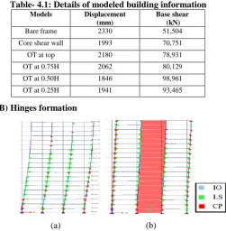
[image:3.595.306.558.403.660.2] [image:3.595.53.274.439.563.2]It has been observed in the figure 4.1 that by introducing outrigger system in model has increases in base force with a better then the bare frame model. But in the all the curves of six model outrigger system which is placed at 0.75H and 0.5H are observed that are getting more base shear values then other four models. The reason for increasing of displacement and base shear is due higher strength and stiffness in structure.
Table- 4.1: Details of modeled building information Models Displacement
(mm)
Base shear (kN)
Bare frame 2330 51,504
Core shear wall 1993 70,751
OT at top 2180 78,931
OT at 0.75H 2062 80,129
OT at 0.50H 1846 98,961
OT at 0.25H 1941 93,465
B) Hinges formation
(a) (b)
Fig- 4.2: Hinge formation of models (a) Hinges of bare frame model (b) Hinges of core shear wall model In the fig- 4.2 (a) shown the hinge formation of bare frame, the first hinge formation at a roof displacement of 1.474m with a base shear of 36,064kN and at the collapse displacement of 2.353m with base shear of 41,374kN. The frame was capture at inner frame of XZ @ Y=-12 the hinge is in range of B-D. The first hinge is observed at
(X=+12) immediate
occupancy level at top of roof. 0
20000 40000 60000 80000 100000 120000 140000
0 1000 2000 3000 4000
B
A
SE
FOR
C
E
(
k
N)
DISPLACEMENT (mm)
shear wall OT at top OT at 0.75H
In the fig- 4.2 (b) shown the hinge formation of core shear wall, the first hinge formation at roof displacement of 0.458m with a base shear of 20,286kN and at the collapse displacement of 2.103m with base shear of 60,752kN. The frame was capture at inner frame of XZ @ Y=-12 the hinge is in range of B-D. The first hinge is observed at immediate occupancy level at top of roof (X=0).
(a) (b)
figure 4.3: Hinge formations of models (a) hinges of outrigger at top model
(b) Hinges of outrigger at 0.75H model
In the fig- 4.2 (a) shown the hinge formation of outrigger at top, the the first hinge formation at roof displacement of 1.249m with a base shear of 51,454kN and at the collapse displacement of 2.113m with base shear of 76,205kN. The frame was capture at inner frame of XZ @ Y=-12 the hinge is in range of B-D. The first hinge is observed as collapse prevention level at top of roof at (X=0).
In the fig- 4.2 (a) shown the hinge formation of outrigger at 0.75H, the first hinge formation at roof displacement of 1.237m with a base shear of 51,976kN and at the collapse displacement of 2.063m with base shear of 80,126kN. The frame was capture at inner frame of XZ @ Y=-12 the hinge is in range of B-D. The first hinge is observed collapse prevention level at top of roof at (X=0).
(a) (b)
Figure 4.4: hinge formations of models (a) hinges of outrigger at 0.50H model (b) Hinges of outrigger at 0.25H model
In the fig- 4.4 (a) shown the hinge formation of outrigger at 0.50H, the roof displacement of 1.879m with a base shear of 94,874kN and at the collapse displacement of 1.853m with base shear of 97,964kN. The frame was capture at inner frame of XZ @ Y=-12 the hinge is in range of B-D. The first hinge is observed as immediate occupancy level at top of roof at (X=12).
In the fig- 4.4 (a) shown the hinge formation of outrigger at 0.25H, the first yield hinge formation at roof displacement of 0.891m with a base shear of 50,826kN and at the collapse displacement of 1.972m with base shear of 90,545kN. The
frame was capture at inner frame of XZ @ Y=-12 the hinge is in range of B-D. The first hinge is observed as collapse prevention level at top of roof at (X=12).
V. OBSERVATIONS
By the present studies we have observed form all the six building models listed below:
Bare frame model has a base shear of 47% lesser than the outrigger system applied at 0.5H of the structure. Bare frame model has a 20.2% less displacement than outrigger at 0.5H structure.
By comparing building models with bare frame building displacement values are reduced by 14.02% ,10.16%, 12.9%, 20.2% and 16.69% for shear wall, outrigger at top, outrigger at 0.75H, outrigger at 0.5H, outrigger at 0.25H building models respectively. So, its concluded that building model of outrigger at 0.5H has lesser displacement.
By comparing building models with outrigger at 0.5H building model base shear values are reduced by 27.7%, 19.42%, 16% and 4% for shear wall, outrigger at top, outrigger at 0.75H, outrigger at 0.25H building models respectively. So, its concluded that building model of outrigger at 0.5H has higher base shear.
Comparison of core shear wall building with outrigger at top building has increased 10.35% in base shear and decreased 5% in displacement.
By comparing the outrigger position at 0.75H building model with outrigger position at 0.25H building has improved 12.23% in base shear and reduced 4.36% in displacement.
VI. CONCLUSION
By the present studies we have conclude from the observation listed below:
Bare frame model has shown more difference in base shear and displacement when compared to outrigger system. By applying the outrigger system at different positions of the total height has given improved results than the core shear wall models.
As core shear wall has less lateral resistance then outrigger system due to imbalance in the failure of exterior columns. And has 25% lesser base shear and 14% reduction in displacement then the outrigger system at 0.5H.
In hinge formation number of hinges are more in core shear wall, when compared to outrigger system. But in bare frame model more collapse hinges have formed at ultimate state.
Outrigger system has a lesser number of collapse hinges at one end side of frame in X direction, when compared to other building models has reached maximum number of hinges at all frames.
By providing more than one outrigger locations in building model has decreases displacement when compared to one outrigger
International Journal of Innovative Technology and Exploring Engineering (IJITEE) ISSN: 2278-3075,Volume-8 Issue-12, October 2019
Finally, we conclude that outrigger at half of height of total building shows optimal values compared with other five models.
VII. SCOPEFORFURTHERSTUDY
In the present study the pushover analysis is carried out for the G+19 story buildings without and with outrigger system. This can be extended to a greater number of floors in a building model.
The plan layout can be done with irregular plan. Further analysis can be carryout with other methods.
REFERENCES
1. Mir M. Ali1 and Kyoung Sun Moon2," Structural Developments in Tall Buildings: Current Trends and Future Prospects", Structures Division, School of Architecture, University of Illinois at Urbana-Champaign, Champaign, IL 61820, USA.
2. P.M.B. Raj Kiran Nanduri1, B.Suresh2, MD. Ihtesham Hussain3," Optimum Position of Outrigger System for HighRise Reinforced Concrete Buildings Under Wind And Earthquake Loadings", Department of civil engineering, Adama Science and technology university, Adama, Ethiopia
3. Chopra AK.Dynamics of structure: theory and application to earthquake engineering.(ERnglewood cliffs,NJ:1995)
4. FEMA-273 (1997),” NEHRP guidelines for the seismic rehabilitation of buildings”, developed by the building seismic safety council for the federal emergency management agency , Washington D.C
5. Srinivasu A and Dr.Panduranga Rao.B, Non-Linear static analysis of multi-storied building, International journal of engineering trends and technology (ILETT) – volume 4 issue 10-Oct 2013.
6. Taranath B. S. Reinforced Concrete Design of Tall Building. Florida, CRC Press, Taylor and Francis Group, 2010.
7. Rama Raju K, M. I. Shereef, N. R. Iyer, S. Gopalakrishnan, “Analysis and Design of RC Tall Building Subjected to Wind and Earthquake Loads”, The Eighth Asia-Pacific Conference on Wind Engineering, Dec-2013, pp 844-852.
8. IS 16700: 2017, “Criteria for Structural Safety of Tall Concrete Buildings”, First Edition, Bureau of Indian Standards.
9. Shivacharan K, Chandrakala S, Narayana G, Karthik N M,”Analysis Of Outrigger System For Tall Vertical Irregularities Structures Subjected To Lateral Loads”, International Journal of Research in Engineering and Technology, Vol-04, Issue-05, pp. 84-88, 2015
AUTHORSPROFILE
Daggula Arvind kumar, M.tech (Structural engineering), Department of civil engineering, Anurag Group of Institutions,Venkatapur, Ghatkesar(M), Medchal(D), Hyderabad, India. 500 088.
Dr. A. Vimala,ProfessorDepartment of civil
engineering,Anurag Group of