Abstract— High voltage (HV) pulses are used in pulsed electric field (PEF) applications to provide an effective electroporation process, a process in which harmful microorganisms are disinfected when subjected to a PEF. Depending on the PEF application, different HV pulse specifications are required such as: the pulse-waveform shape, the voltage magnitude, the pulse duration, and the pulse repetition rate. In this paper, a generic pulse-waveform generator (GPG) is proposed, the GPG topology is based on half-bridge modular multilevel converter (HB-MMC) cells. The GPG topology is formed of four identical arms of series connected HB-MMC cells forming an H-bridge. Unlike the conventional HB-MMC based converters in HVDC transmission, the GPG load power flow is not continuous which leads to smaller size cell capacitors utilization, hence smaller footprint of the GPG is achieved. The GPG topology flexibility allows the controller software to generate a basic multilevel waveform which can be manipulated to generate the commonly used PEF pulse-wave forms. Therefore, the proposed topology offers modularity, redundancy and scalability. The viability of the proposed GPG converter is validated by MATLAB/Simulink simulation and experimentation.
Index Terms—bacterial decontamination, electroporation, H-Bridge, modular multilevel converters (MMC), pulsed electric field, pulse waveforms generator.
I. INTRODUCTION
pplying pulsed electric field (PEF) for decontamination and sterilization from bacteria and harmful microorganisms is used in applications such as; water disinfection, air pollution control, medical treatment, and food sterilization [1]-[3]. PEF based applications depend on high voltage (HV) pulse generators, which are responsible for creating the desired HV pulses with specific characteristics such as waveform-shape, pulse polarity, duration, and repetition frequency.
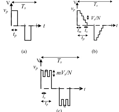
[image:1.612.49.303.627.702.2](a) (b) (c)
Fig. 1. Commonly used pulse-waveforms in PEF applications.
Among the vast range of possible HV pulse-waveforms, rectangular and exponential pulses, as shown in Figs. 1a and 1b, are commonly used for water disinfection, air pollution control and medical treatment [4]. Additionally, pulses of combined narrow and wide pulse durations, shown in Fig. 1c, are preferred in food sterilization to sterilize food safely without altering its nutritional values [5].Usually, such pulse-waveforms are either of monopolar or bipolar in PEF applications. Effectively, the generated pulses should be in the kilo-volt magnitude range (1-100 kV) with pulse durations extending between nanoseconds and milliseconds [6]; generally decreasing in duration as voltage increases.
Classical generators are normally used to generate HV pulses, such as Marx generators, pulse forming networks, and Blumlein lines [7]. However, with the continuing HV semi-conductor switch development, mainly the increased voltage ratings and higher switching frequency capability, it is possible to generate the necessary HV pulses via power-electronics based converters. In a solid-state Marx generator, as an example, the semi-conductor switches operate to control the charging and discharging of its capacitors such that they charge in parallel then discharge in series across the load [8]-[10]. In [11] buck-boost converter modules are connected in series/parallel to generate HV pulses with proper turn ON/OFF operation of the semi-conductor switches. Half-bridge modular multilevel converter (HB-MMC) cells are used in [12] to generate HV from a low-voltage supply by charging cell capacitors sequentially then discharging them in series across the load. In [13]-[14] modified HB-MMC cells are used to form one-phase leg inverter, where a series diode between adjacent cells modification affords sensorless operation of the MMC cell-voltages when employing a specific ON/OFF switching sequence. Moreover, in [15] the conventional one-phase leg inverter of HB-MMC cells, operates in sensoreless mode by applying the desired modulating signal with phase shifted carriers.
Nevertheless, the pulse-waveform generated via both classical and modern semi-conductor based pulse generators is mainly monopolar rectangular. Thus, to generate different pulse-waveforms when utilizing the same converter, some modifications should be considered in the power topology by either adding extra switches or by combining more than one converter to generate a specific pulse waveform, as in [5] to generate the combined narrow and wide pulse durations. t
V
t
V
t
V
A Modular Multilevel Generic Pulse-Waveform
Generator for Pulsed Electric Field Applications
Mohamed A. Elgenedy,
Student Member, IEEE
, A. Darwish, Shehab Ahmed,
Senior Member, IEEE
,
and Barry W. Williams
Fig. 2. The proposed GPG topology along with the controller software block diagram.
(a) (b)
[image:2.612.67.315.257.438.2](c)
Fig. 3. GPG basic multilevel pulse-waveform. Fig. 4. Generation of different pulse-waveforms from the basic GPG multilevel pulse-waveform. (a) Rectangular. (b) Ramp. (c) Combined wide and narrow.
Therefore, there is a specific pulse generator for every associated PEF application to generate its required pulses. Also, for a given pulse-waveform, some generators can only generate pulses of monopolar or bipolar shapes [16].
This paper is an extension to the work presented in [17], where, individual voltage sensors are added to provide individual cell-voltage measurement to the controller software. This modification allows generation of bipolar multilevel pulse-waveform, which can be manipulated to generate rectangular, ramp as well as combined narrow and wide pulse-waveforms by only changing the controller software algorithm without changing any physical connections in the circuit topology. The ramp voltage waveform mimics the features of a true exponential waveform, shown in Fig. 1b, by allowing rise time and decay time control. Moreover, the feature of generating high frequency rectangular pulses in [17] can be obtained by disabling the voltage-measurements and operate in the sensorless mode.
Additionally, not only bipolar or monopolar pulses can be generated, but pulse-waveforms with special characterisation are also possible. For example, the proposed generic pulse-
waveform generator (GPG) can change the duration of a particular polarity or combining both null-load voltage (NLV) durations in bipolar pulses.This allows generating the positive pulse and the negative pulse sequentially to increase the mechanical stresses in lethal electroporation process and prevent the fast reseal of the microorganisms under treatment.
In the proposed GPG, the use of a HV switch to chop the HV dc-voltage to form the pulses, adopted in [9], [10] and [18] for example, is avoided. Similarly, in [12] the HV series-connected diodes used to bypass the load during charging the cell-capacitors is also avoided. Hence, GPG topology flexibility and scalability are viable and the magnitude of the utilized dc-voltage is constrained only by the application requirements, while the repetition rate is limited by the speed of the controller to execute the software instructions and the pulse duration is limited by the speed of the utilized semi-conductor switches.
Utilizing four arms of the HB-MMC cells in the GPG provides output flexibility by software control, along with hardware modularity, scalability, and redundancy. Also each GPG cell capacitance is small, which drastically reduces the converter cost,
Cell Cell Cell La Vs A rm 1 io + -Ls vo is Cell Cell Cell La Cell Cell Cell La Cell Cell Cell La v11 v12 v1N v41 v42 v4N v2N v22 v21 v3N v32 v31 Ar m 3 Ar m 2 A rm 4 VAB Tx Tm CZN + -VZN A B Cell ZN VZN
Multilevel pulse generation (Sensor based mode) Rectangular pulse generation
(sensorless mode) [17]
Cell switching signals
Operation selection
V11 VZN
Cell
11 Cell ZN
Basic multilevel pulse
exponential pulse
Combined wide and narrow pulse
Pulse-waveform selection
Block diagram of the controller software
Tx
Tm VAB
ON ON OFF OFF 0 VZN
Cell Switching States
Ts tp tm tx vp
Vs/N
t V 4 3 2 1 + -P os it ive p u ls e ge n er at ion vi a A rm s 3 an d 4 N egat ive p u ls e ge n er at ion vi a A rm s 1 an d 2 N ul l L oad V ol tage (N V L ) d u rat ion N ul l L oad V ol tage (N V L ) d u rat ion Ts tp vp t
V Ts
tp
tm tx
vp
Vs/N
[image:2.612.355.553.258.445.2]footprint and weight. Also, individual cell-voltages are balanced using the conventional sorting algorithm used in HB-MMC topologies for HVDC transmission applications, where cell capacitors are continuously rotated and sequenced based on the measurements of their individual voltages [19]-[20].
It should be noted that, by using one phase-leg of a three phase HB-MMC based inverter similar pulse waveforms can be generated by changing the modulating reference waveform, which is responsible of turning ON/OFF the MMC cells in order to mimic the modulating signal across the load. Usually a carrier based pulse width modulation technique is adopted as in [15]. However, applying a pulse width modulation technique to control the phase-leg inverter, fed from HVDC input, 𝑉𝑠, suffers from the following limitations:
Two bulky capacitors will be required to form the ±½𝑉𝑠with a mid-point connection.
For the same 𝑉𝑠 input the peak of the generated bipolar pulses will be 50% when compared with the generated pulses of the GPG topology.
The generated pulses are bipolar by default connection, however, for monopolar pulses the reference point should be moved to ground [14]. So that, the converter cannot generate both monopolar and bipolar pulses without physical changes to the power topology.
The proposed GPG converter is described in section II, its operating sequence is outlined in section III, and simulation and experimental result are present in sections IV and V respectively.
II. GPGTOPOLOGY DESCRIPTION
By adding voltage sensors for the individual cell-capacitors in the hardware topology and changing the controller software in the modular multilevel pulse generator in [17], the proposed GPG gains the feature of generating wide range of pulse-waveforms, as shown in Fig. 2.
The GPG topology, shown in Fig. 2, consists of four arms of 𝑁 series connected HB-MMC cells creating an H-bridge, sourced from a dc voltage supply 𝑉𝑠 via an input inductor 𝐿𝑠. For proper operation each arm should withstand the dc-link voltage 𝑉𝑠. Each arm has a small series arm inductor 𝐿𝑎 to supress the inrush current between cell-capacitors during their insertion process. Depending on the ON/OFF switching sequence of the complimentary switches 𝑇𝑚 and 𝑇𝑥, the cell- terminal voltage 𝑉𝐴𝐵 is either the capacitor-voltage or zero as illustrated in the cell-switching table in Fig. 2.
The individual cell-voltages 𝑉𝑍𝑁, where Z = 1, 2, 3 and 4 is the arm number and 𝑁 is the cell number in the arm 𝑍, are fed to the controller software to assure their voltage balance around 𝑉𝑍𝑁= 𝑉𝑠⁄𝑁.
The GPG basic generated multilevel pulse waveform 𝑣𝑝 is shown in Fig. 3, and can be defined by four sequential intervals: the positive pulse, the positive NLV, the negative pulse, and the negative NLV, respectively.
Controlling the five parameters of this basic waveform
allows generation of any desired pulse waveform, like the shown in Fig. 1. These five parameters are: repetition time 𝑇𝑠, total pulse time 𝑡𝑝, pulse plateau time 𝑡𝑚, cell-voltage step 𝑉𝑠⁄𝑁 and step voltage-level applied time 𝑡𝑥. Accordingly, the desired pulse-waveform parameters are fed to the controller software to insert/bypass the required cells based on their voltage measurements as shown in Fig. 2. Moreover, the controller software allows two types of operation, the sensorless mode (in which the sensors input voltage is disabled) and the multilevel mode. The sensorless mode is utilized for rectangular pulse generation while the multilevel mode allow different pulse generation as shown in Fig. 2.
Although the default generated pulses are bipolar, the omission of either polarity during pulse generation yields monopolar pulses generation. The imitated pulse waveform of Fig. 1 generated by manipulating the GPG basic pulse waveform controlling attributes are shown in Fig. 4. In Fig. 4a the rectangular pulse waveform can be generated by setting 𝑡𝑝= 𝑡𝑚 and 𝑡𝑥= 0, hence, all the corresponding arm cell-capacitors will operate simultaneously. The generation of ramp pulse-waveforms, Fig. 4b, is possible by inserting all corresponding cell-capacitors for duration 𝑡𝑚, then bypassing them one by one gradually to reduce the voltage to zero in 𝑁𝑡𝑥, with total pulse time 𝑡𝑝= 𝑡𝑚+ 𝑁𝑡𝑥. The combined wide and narrow pulses, Fig. 4c, can be generated by setting 𝑡𝑝 as the wide pulses duration with an amplitude of 𝑉𝑠, and the narrow pulses of magnitude (𝑉𝑠−𝑚𝑉𝑠⁄𝑁) and duration 𝑡𝑥, where 𝑚 is the number of bypassed cells in the corresponding arms.
III. GPGOPERATING SEQUENCE
Each cell-voltage is continuously measured, compared with other cell-voltages in the corresponding arm, and the capacitor voltages are sorted. Accordingly, the highest voltage capacitor among the available capacitors is inserted first at each voltage level during the transition from 0 to ±𝑉𝑠, while the lowest cell-voltage is bypassed first during the transition from ±𝑉𝑠 to 0. Thus, if one of the arm 𝑁 capacitors is inserted, the software algorithm will select from the remaining 𝑁 − 1 capacitors to build the next voltage level and so on, until the desired pulse waveform is created.
Fig. 5 shows the circuit configurations and the operating sequences for each of the four intervals. Based on the desired pulse waveform, the controller software will allow the insertion and the bypass of the corresponding arm capacitors as follows:
During positive pulse generation Arm3 and Arm4capacitors are inserted to discharge across the load through the bypassed cells in arms 1 and 2 respectively, as shown in Fig. 5a.
(a) (b) (c) (d)
Fig. 5. Circuit configurations of the GPG during bipolar pulse generation. (a) Positive pulse. (b) Positive NLV. (c) Negative pulse. (d) Negative NLV.
TABLE I Simulation Specification
Parameter Rectangular waveforms Other
DC input voltage (𝑉𝑠) 10 kV Input inductance (𝐿𝑠) 1.5 mH
Number of cells/arm (𝑁) 10
Repetition time (𝑇𝑠) 100 μs Arm inductance (𝐿𝑎) 15 μH Load resistance (𝑅) 500 Ω Cell capacitance (𝐶𝑐) 1 μF 5 μF Percent voltage ripple (𝛽) < 0.05 Safety factor (𝛼) 1
The positive and negative NLV durations allow charging of the lower/upper arms by bypassing the other upper/lower arms. Accordingly, the load voltage reduced to zero and the charging current flows through the bypassed arms to charge the inserted cell-capacitors of the other arms. The charging cells are inserted simultaneously forming total capacitance of (𝐶𝑍𝑁⁄𝑁) as shown in Figs. 5b and 5d.
IV. SIMULATION RESULTS
The proposed GPG is assessed using MATLAB/Simulink simulations, with the parameters given in Table I for generating the rectangular (the sensorless mode) and other pulse waveform shapes (the sensor based mode). The PEF load, which is normally contained in a treatment chamber, can be modelled electrically by 𝑅𝐶 equivalent combination, however; for pulse durations in micro-second order and higher the load can be modelled as resistance (𝑅) only [21]-[22]. Additionally, the individual cell-capacitance 𝐶𝑍𝑁 is sized as in [17] based on
𝐶𝑍𝑁=
𝛼(½ − 𝛿) 𝛿𝑇𝑠
𝛽𝑅 𝑁 (1)
where 𝛽 is the percent peak to peak voltage ripple of the individual cell-capacitor, 𝛿 = 𝑡𝑝⁄𝑇𝑠 is the pulse duty ratio, and 𝛼 ≥ 1 is a safety factor to account for the neglected losses.
Moreover, the input dc-link inductor 𝐿𝑠 should provide a current path from the dc-link voltage to charge the four arms capacitors while avoiding resonance with the charging arm capacitors. Therefore, based on the calculated equivalent arm capacitance and the operating repetition time an estimation of the inductance of 𝐿𝑠 will be
𝐿𝑠>
½𝑇𝑠2𝑁
(2𝜋)2𝐶 𝑍𝑁
(2)
The simulations assess the ability of the GPG to mimic the commonly used pulse-waveforms in PEF applications as well as the flexibility of the converter to control the generated pulse attributes via the controller software-algorithm without requiring any physical changes to the circuit topology.
(a)
(b)
Fig. 6. Simulation of bipolar HV pulses, 𝑡𝑝= 10μs. (a) Output voltage pulses. (b) The four arms capacitor voltages.
+
-Vs
vo Ls
C31
iarm3
iarm4
io 1
is
C32
C3N
C41
C42
C4N
+
-Vs
vo Ls
CZN/N
io= 0 2
is
CZN/N
+
-Vs
vo Ls
iarm1
io
3
iarm2 is C
11
C12
C1N
C21
C22
C2N
+
-Vs
vo Ls
io= 0 4
is
CZN/N
CZN/N
0 0.5 1 1.5 2
-10 -5 0 5 10
Cycles (Ts = 100us)
V
ol
ta
ge
,
kV
0 0.5 1 1.5 2 2.5 3 3.5 4 4.5 5
0.95 1 1.05
Cycles (Ts = 100 us)
V
ol
ta
ge
,
[image:4.612.333.546.412.706.2](a)
(b)
(c)
Fig.7. Simulation of different rectangular HV pulses. (a) 10μs negative
monopolar. (b) 2μs positive monopolar. (c) Combined NLV durations pulses.
[image:5.612.326.552.46.377.2]The simulation results when generating 10μs rectangular bipolar HV pulses at 10 kHz repetition frequency are shown in Fig. 6. The output pulses are shown in Fig. 6a; the four arms 40 capacitor voltages are given in Fig. 6b, where, each capacitor voltage fluctuates around 1000 V, that is 𝑉𝑠⁄𝑁, with less than 5% voltage ripple.
The converter controller is programmed to generate 10μs rectangular negative monopolar pulses and 2μs positive monopolar pulses at a 10 kHz repetition frequency. The simulation results are shown in Figs. 7a and 7b respectively. Generating rectangular pulses of different positive and
negative durations (4μs and 2μs respectively) with combined
NLV durations is explored in Fig.7c.
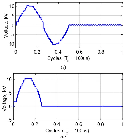
The basic GPG multilevel bipolar pulse-waveform is shown in Fig. 8a, with 𝑡𝑥= 1 µs and 𝑡𝑚= 6 µs at 10 kHz repetition frequency, while the corresponding four arms 40 capacitor voltages, fluctuating around 1000 V, are shown in Fig. 8b. Combined NLV durations bipolar multilevel pulses are shown in Fig. 9a, while monopolar multilevel pulses are shown in Fig. 9b.
(a)
(b)
Fig. 8. Simulation of basic GPG multilevel HV pulse-waveform. (a) Output voltage pulses. (b) 4 arms capacitor voltages.
(a)
(b)
Fig. 9. Simulation of GPG multilevel HV pulses with 𝑡𝑥= 1 µs and 𝑡𝑚= 6 µs. (a) Bipolar combined NLV durations. (b) Positive-monopolar.
0 0.5 1 1.5 2
-10 -5 0 5
Cycles (Ts = 100us)
V
ol
ta
ge
,
kV
0 0.5 1 1.5 2
-5 0 5 10
Cycles (Ts = 100us)
V
ol
ta
ge
,
kV
0 0.2 0.4 0.6 0.8 1 1.2 1.4 1.6 1.8 2
-10 -5 0 5 10
Cycles (Ts = 100us)
V
ol
ta
ge
,
kV
0 0.2 0.4 0.6 0.8 1 1.2 1.4 1.6 1.8 2
-10 -5 0 5 10
Cycles (Ts = 100us)
V
ol
ta
ge
,
kV
1 µs 6 µs 1 kV
0 0.5 1 1.5 2 2.5 3 3.5 4 4.5 5 0.9
0.95 1 1.05 1.1
Cycles (Ts = 100us)
V
o
lt
a
g
e
,
k
V
0 0.2 0.4 0.6 0.8 1
-10 -5 0 5 10
Cycles (Ts = 100us)
V
ol
ta
ge
,
kV
0 0.2 0.4 0.6 0.8 1
-5 0 5 10
Cycles (Ts = 100us)
V
ol
ta
ge
,
[image:5.612.59.286.54.403.2] [image:5.612.334.540.413.642.2](a)
[image:6.612.316.574.60.675.2](b)
Fig.10. Simulation of GPG ramp HV pulses with 𝑡𝑥= 1 µs and 𝑡𝑚= 6 µs. (a) Bipolar and (b) Monopolar.
(a)
(b)
Fig.11. Simulation of GPG combined wide and narrow HV pulses with 𝑚 = 5 and 𝑡𝑥= 5 µs. (a) Bipolar. (b) Monopolar.
Exploiting the flexibility of the basic multilevel pulse-waveform affords the possibility of generating ramp and combined wide and narrow pulse-waveforms. Fig. 10a shows bipolar ramp pulses with 𝑡𝑥= 1 µs and 𝑡𝑚= 6 µs, while its monopolar version of pulses is depicted in Fig. 10b. With 𝑚 = 5 and 𝑡𝑥= 5 µs bipolar combined wide and narrow pulses are shown in Fig. 11a and its monopolar version is shown in Fig. 11b.
It should be noted that, the observed small voltage droop in the pulse peak in the simulation results is due to the decrease of the capacitor energy during pulse generation, this droop is reciprocal to the cell capacitor size viz. the larger the capacitor size the smaller the voltage droop and vice versa. This can be mitigated by using a safety factor 𝛼 > 1 during the selection stage of the cell capacitance size.
TABLE II Experimental Specification
Parameter Rectangular waveforms Other
DC input voltage (𝑉𝑠) 250 V 150V Input inductance (𝐿𝑠) 0.5 mH 2.5 mH
Number of cells/arm (𝑁) 3
Repetition time (𝑇𝑠) 100 μs 1000 μs Arm inductance (𝐿𝑎) 10 μH
Load resistance (𝑅) 500 Ω 100Ω Cell capacitance (𝐶𝑐) 1 μF 15 μF Percent voltage ripple (𝛽) < 0.05 Safety factor (𝛼) 1
Fig.12. The scaled-down experimental rig.
(a)
(b)
Fig.13. Experimental results for rectangular bipolar pulses with 𝑡𝑝= 10 µs. (a) Output voltage pulses. (b) A cell capacitor voltage in each of the 4 arms.
0 0.2 0.4 0.6 0.8 1
-10 -5 0 5 10
Cycles (Ts = 100us)
V
ol
ta
ge
,
kV
0 0.2 0.4 0.6 0.8 1
-5 0 5 10
cycles (Ts = 100us)
V
ol
ta
ge
,
kV
0 0.5 1 1.5 2
-10 -5 0 5 10
Cycles (Ts = 100us)
V
ol
ta
ge
,
kV
0 0.5 1 1.5 2
-10 -5 0 5 10
Cycles (Ts = 100us)
V
ol
ta
ge
,
kV
Monitoring
Vs
Ls
Voltage Sensors Gate-drive and
dead-time circuits
R CZN
3 cells Arm
eZDSP
TMS320F28335 PC-Host
Ref
Time: 25µs/div. Voltage: 100V/div.
Ref
[image:6.612.75.271.295.517.2](a)
(b)
Fig.14. Experimental results for rectangular bipolar pulses. (a) Combined NLV durations with positive pulse of 𝑡𝑝= 10 µs and negative pulse of 𝑡𝑝= 5 µs. (b) Monopolar with 𝑡𝑝= 5 µs.
(a)
(b)
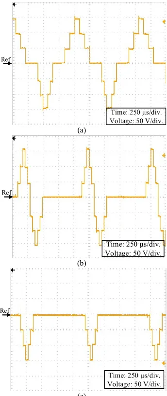
Fig.15. Experimental results for GPG basic multilevel bipolar pulses with 𝑡𝑥= 𝑡𝑚= 40 µs and voltage-level of 50 V. (a) Output voltage pulses. (b) A cell capacitor voltage in each of the 4 arms.
(a)
(b)
(c)
Fig.16. Experimental results for GPG multilevel bipolar pulse with voltage-level of 50 V. (a) Bipolar asymmetrical. (b) Combined NLV durations. (c) Negative monopolar.
V. EXPERIMENTAL RESULTS
A scaled-down experimental rig is used to validate the performance of the GPG and explore its software-algorithm flexibility in producing common PEF pulse-waveforms. Ultra-fast IGBT switches (STGW30NC60WD) are used for the circuit, while the control algorithm was implemented with
Texas Instruments’ eZDSP TMS320F28335. The
experimental specifications for generating the rectangular and other pulse waveforms are given in Table II, while the experimental rig is shown in Fig. 12.
In the experimental rig, illustrated in Fig. 12, the software control code follows the operating sequence detailed in section III and is written using Matlab compiler. Then the main Matlab code is compiled to C and assembly, and downloaded to the DSP via a USB port. Isolated voltage sensors sent their measurement values to the DSP via an analogue/digital port (A/D). Based on these measurements, after sorting, the DSP code decides which MMC-cell should be inserted/bypassed, sending a control ON/OFF signal through a DSP digital output Ref
Time: 25 µs/div. Voltage: 100 V/div.
Ref
Time: 25 µs/div. Voltage: 100 V/div.
Ref
Time: 250 µs/div. Voltage: 50 V/div.
Ref
Time: 500 µs/div. Voltage: 20 V/div.
Ref
Time: 250 µs/div. Voltage: 50 V/div.
Ref
Time: 250 µs/div. Voltage: 50 V/div.
Ref
[image:7.612.91.260.47.318.2] [image:7.612.355.527.49.456.2] [image:7.612.92.261.362.636.2]port to the corresponding IGBT gate drive. The gate drive circuits (an individual isolated circuit for each IGBT switch) provide isolation between the control stage and the power stage.
Fig. 13 shows the experimental results for bipolar rectangular pulses with 𝑡𝑝= 10 µs. The output voltage pulses and the voltage across one capacitor in each of the 4 arms are shown in Figs. 13a and 13b, respectively. Since the peak of the output pulse is 250V, each capacitor voltage should be around 83.3V, as shown in Fig.13b. Bipolar pulses of combined NLV durations with positive and negative pulse durations of 10 µs and 5µs are shown in Fig. 14a while 5 µs positive-monopolar pulses are shown in Fig. 14b.
The basic GPG multilevel pulse-waveform with four positive and four negative voltage-levels is shown in Fig. 15a with 𝑡𝑥= 𝑡𝑚= 40 µs and a 1000 µs repetition time. The corresponding voltage across one capacitor in each of the 4 arms is shown in Fig. 15b, which implies that each voltage level is 50 V and, accordingly, the peak pulse voltage is 150V. Generating multilevel pulse-waveform with asymmetric positive/negative pulse durations is shown in Fig. 16a where the positive pulse duration is twice the duration of its negative counterpart which has 𝑡𝑥= 𝑡𝑚= 40. Combined NLV durations bipolar multilevel pulses are shown in Fig. 16b with 𝑡𝑥= 𝑡𝑚= 40 while negative-monopolar multilevel pulses are shown in Fig. 16c.
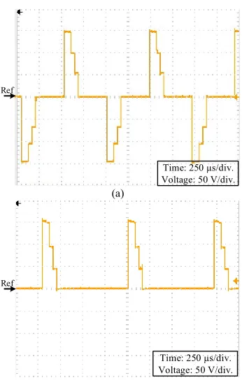
Bipolar ramp pulses with 𝑡𝑥= 40 µs and 𝑡𝑚= 80 µs are shown in Fig. 17a while the monopolar version is shown in Fig. 17b. The combined wide and narrow pulses with 𝑚 = 2 and 𝑡𝑥= 40 µs are shown in Fig. 18a and Fig. 18b for bipolar pulses and monopolar pulses, respectively.
VI. CONCLUSION
This paper presents a generic pulse-waveform generator which mimics the dominating HV pulse-waveforms in PEF applications. The proposed topology generates a multilevel pulse-waveform where its attributes can be manipulated, via the GPG controller software-algorithm with the aid of individual cell-voltage sensing. The cell-voltages are maintained around 𝑉𝑠⁄𝑁 by continuously measuring their individual voltages and applying the sorting and rotating algorithm. Accordingly, there are two modes of converter operation namely: the sensorless mode for rectangular pulse waveform generation and the sensor based mode for multilevel pulse generation. Therefore, the multilevel mode allows generation of ramp (which mimics the features of a true exponential pulses) and combined narrow and wide pulses. Normally, using one phase-leg of a three phase HB-MMC based inverter can generate different pulse waveforms by changing the modulating reference waveform in a carrier based pulse width modulation technique. However, only bipolar pulses will be generated with peak voltage of 50% when compared with the generated pulses of the GPG topology for the same HV dc input, and two bulky capacitors will be required to form the dc bus with a mid-point connection.
(a)
[image:8.612.355.528.56.328.2](b)
Fig.17. Experimental results for GPG ramp pulses with 𝑡𝑥= 40 µs and 𝑡𝑚= 80 µs. (a) Bipolar. (b) Monopolar.
(a)
[image:8.612.356.528.362.632.2](b)
Fig.18. Experimental results for GPG combined wide and narrow pulses with 𝑚 = 2 and 𝑡𝑥= 40 µs. (a) Bipolar. (b) Monopolar.
The GPG can generate both bipolar and monopolar HV pulse-waveforms with micro-second pulse durations with controllable voltage magnitude, pulse duration and pulse repetition frequency characteristics. Hence, the proposed topology provides flexibility via its controller software-algorithm, along with hardware modularity, scalability, and
Ref
Time: 250 µs/div. Voltage: 50 V/div.
Ref
Time: 250 µs/div. Voltage: 50 V/div.
Ref
Time: 250 µs/div. Voltage: 50 V/div.
Ref
redundancy. Simulations and experimental results confirm the feasibility of the proposed GPG promoting it for PEF applications.
ACKNOWLEDGMENT
This work was supported by the Qatar National Research Fund (a member of the Qatar Foundation) under NPRP Grant (7-203-2-097). The statements made herein are solely the responsibility of the authors.
REFERENCES
[1] Q. Bai-Lin, Z. Qinghua, G. V. Barbosa-Canovas, B. G. Swanson, and P. D. Pedrow, "Inactivation of microorganisms by pulsed electric fields of different voltage waveforms," IEEE Trans. Dielect. Elect.
Insulation, vol. 1, no. 6, pp. 1047-1057, 1994.
[2] A. Sheikholeslami and J. Adabi, "High-voltage pulsed power supply to generate wide pulses combined with narrow pulses," IEEE Trans.
Plasma Sci., vol. 42, no. 7, pp. 1894-1901, Jul. 2014.
[3] H. Bluhm, Pulsed power systems: principles and applications, Berlin, Springer, 2006.
[4] M. Rebersek and D. Miklavcic, "Advantages and disadvantages of different concepts of electroporation pulse generation,"
Automatika‒Journal for Control, Measurement, Electronics,
Computing and Communications, vol. 52, no. 1, 2011.
[5] W. Tsai-Fu, T. Sheng-Yu, and H. Jin-Chyuan, "Generation of pulsed electric fields for processing microbes," IEEE Trans. Plasma Sci., vol. 32, no. 4, pp. 1551-1562, 2004.
[6] J. Raso and V. Heinz, Pulsed electric fields technology for the food
industry: fundamentals and applications, New York, London,
Springer, 2006.
[7] J. Mankowski and M. Kristiansen, "A review of short pulse generator technology," IEEE Trans. Plasma Sci., vol. 28, no. 1, pp. 102-108, Feb. 2000.
[8] E. Veilleux, B. T. Ooi, and P. W. Lehn, "Marx dc-dc converter for high-power application," Power Electronics, IET, vol. 6, no. 9, pp. 1733-1741, 2013.
[9] T. Sakamoto, A. Nami, M. Akiyama, and H. Akiyama, "A Repetitive Solid State Marx-Type Pulsed Power Generator Using Multistage Switch-Capacitor Cells," IEEE Trans. Plasma Sci., vol. 40, no. 10, pp. 2316-2321, 2012.
[10] M. Rezanejad, A. Sheikholeslami, and J. Adabi, "Modular switched capacitor voltage multiplier topology for pulsed power supply," IEEE
Trans. Dielect. Elect. Insulation, vol. 21, no. 2, pp. 635-643, Apr.
2014.
[11] S. Zabihi, F. Zare, G. Ledwich, A. Ghosh, and H. Akiyama, "A new pulsed power supply topology based on positive buck-boost converters concept," IEEE Trans. Dielect. Elect. Insulation, vol. 17, no. 6, pp. 1901-1911, Dec. 2010.
[12] A. A. Elserougi, A. M. Massoud, and S. Ahmed, "A modular high-voltage pulse-generator with sequential charging for water treatment applications," IEEE Trans. Ind. Electron., vol. 63, no. 12, pp. 7898-7907, 2016.
[13] L. L. Rocha, J. F. Silva, and L. M. Redondo, "Multilevel high-voltage pulse generation based on a new modular solid-state switch," IEEE
Trans. Plasma Sci., vol. 42, no. 10, pp. 2956-2961, Oct. 2014.
[14] L. L. Rocha, J. F. Silva, and L. M. Redondo, "Seven-level unipolar/bipolar pulsed power generator," IEEE Trans. Plasma Sci., vol. 44, no. 10, pp. 2060-2064, 2016.
[15] A. A. Elserougi, A. M. Massoud, and S. Ahmed, "Modular multilevel converter-based bipolar high-voltage pulse generator with sensorless capacitor voltage balancing technique," IEEE Trans. Plasma Sci., vol. 44, no. 7, pp. 1187-1194, 2016.
[16] L. M. Redondo and J. F. Silva, "Flyback versus forward switching power supply topologies for unipolar pulsed-power applications,"
IEEE Trans. Plasma Sci., vol. 37, no. 1, pp. 171-178, Jan. 2009.
[17] M. A. Elgenedy, A. Darwish, S. Ahmed, and B. W. Williams, "A modular multilevel-based high-voltage pulse generator for water disinfection applications," IEEE Trans. Plasma Sci., vol. 44, no. 11, pp. 2893-2900, 2016.
[18] A. Elserougi, S. Ahmed, and A. Massoud, "High voltage pulse generator based on DC-to-DC boost converter with capacitor-diode voltage multipliers for bacterial decontamination," IECON 2015 -
41st Annual Conference of the IEEE 2015, pp. 322-326.
[19] G. P. Adam, O. Anaya-Lara, G. M. Burt, D. Telford, B. W. Williams,
and J. R. McDonald, “Modular multilevel inverter: Pulse width
modulation and capacitor balancing technique,” Power Electron. IET,
vol. 3, pp. 702–715, 2010.
[20] A. Nami, L. Jiaqi, F. Dijkhuizen, and G. D. Demetriades, “Modular
multilevel converters for HVDC applications: Review on converter cells and functionalities,” IEEE Trans. Power Electron., vol. 30, no. 1, pp. 18–36, Jan. 2015.
[21] K. H. Schoenbach, R. P. Joshi, R. H. Stark, F. C. Dobbs, and S. J. Beebe, "Bacterial decontamination of liquids with pulsed electric fields," IEEE Trans. Dielect. Elect. Insulation, vol. 7, no. 5, pp. 637-645, 2000.
[22] M. A. Elgenedy, A. Darwish, S. Ahmed, and B. W. Williams, "A transition arm modular multilevel universal pulse-waveform generator for electroporation applications," IEEE Trans. Power
Electron., vol. PP, no. 99, pp. 1-1, 2017.
Mohamed A. Elgenedy (S’15) received the B.Sc. (with first-class honors) and M.Sc. degrees in Electrical Engineering from Alexandria University, Egypt in 2007 and 2010 respectively. Currently he is working toward the Ph.D. degree at the University of Strathclyde, Glasgow, U.K. He is also an assistant lecturer with the Electrical Engineering Department, Faculty of Engineering, Alexandria University.
In 2012, he was with Spiretronic LLC, Houston, TX, USA, as a Research Engineer. From 2013 to 2014, he was a Research Associate at Texas A&M University at Qatar. His research interests include high power electronics, pulse power generator, electric machine drives, energy conversion, and renewable energy.
Ahmed Darwish received the B.Sc. and M.Sc. degrees in electrical engineering from the Faculty of Engineering, Alexandria University, Alexandria, Egypt, in 2008 and 2012, respectively, and the Ph.D. degree in electric engineering from the Department of Electronic and Electrical Engineering, University of Strathclyde, Glasgow, U.K., in 2015. From 2009 to 2012, he was a Research Assistant at Texas A&M University at Qatar, Doha, Qatar. He is currently a Research Associate with PEDEC Group at the University of Strathclyde. His research interests include dc–dc converters, multilevel converters, electric machines, digital control of power electronic systems, energy conversion, renewable energy, and power quality.
Barry W. Williams received the M.Eng.Sc. degree from the University of Adelaide, Adelaide, Australia, in 1978, and the Ph.D. degree from Cambridge University, Cambridge, U.K., in 1980. After seven years as a Lecturer at Imperial College, University of London, London, U.K., he was appointed to a Chair of Electrical Engineering at Heriot-Watt University, Edinburgh, U.K, in 1986.