•
UNISYS
5074/8494
Disk Subsystem
Programming
Reference Manual
Copyright © 1988 Unisys Corporation All Rights Reserved
Unisys is a trademark of Unisys Corporation
Priced Item
December 1987
terms and conditions of a duly executed Program Product License or Agreement to purchase or lease equipment. The only warranties made by Unisys, if any, with respect to the products described in this document are set forth in such License or Agreement. Unisys cannot accept financial or other responsibility that may be the result of your use of the information in this document or software material, including direct, indirect, special or consequential damages.
You should be very careful to ensure that the use of this information and/or software material complies with the laws, rules, and regulations of the jurisdictions with respect to which it is used.
The information contained herein is subject to change without notice. Revisions may be issued to advise of such changes and/or additions.
We will use your comments to
NOTE: Please do this an
(Document Title)
(Document No.) (HAVis/on No.)
From:
(Name of User)
(Business Address)
FOLD
FIRST CLASS PERMIT NO. 21 BLUE BEll, PA.
POSTAGE WilL BE PAID BY ADDRESSEE
Unisys Corporation
EjMSG Product Information Development
PO
Box 500 C1-NE6 Blue Bell, PA 19422-99901111111.11111111"
1.1111.11,1111.
1111,1,,1111111.1
iI
5074/8494 Disk Subsystem
This Library Memo announces the release of the 5074/8494 Disk Subsystem
Reference Manual, UP-11627.
The 5074/8494 Disk Subsystem is a single cabinet disk subsystem consisting of one disk control unit and two 308 million byte disk drives. it can be expanded to two disk control units and eight disk drives in one cabinet.
The 5074/8494 disk subsystem can operate on either a block multiplexer channel (5074-00) or a System 80 10/20 selector channel (5074-01).
This manual is intended as a reference for experienced programmers and systems analysts.
Copies of this manual may be ordered from your Unisys representative.
Mailing Lists MAC, MBZ, MB38, MCZ, MMZ, MX3, MX5, MX6, MX8, MXX, MY1, MY3, MY5, MY6, and MY7
Mailing lists MBW, MBWA, and MU9Z
(104 pages)
Section
Cover
Title Page/Disclaimer
User Comment Form
PSS
About This Manual
Contents
Section 1
Section 2
Section 3
Section 4
Section 5
Section 6
Section 7
Appendix A
Glossary
Index
Back Cover
UP-11627
Page Status Summary
Issue: UP-11627
Pages Update Section
1
i-iii
1- 5
1-8
1-7
1-10
1- 25
1-6
1-10
1-15
1-2
,- 2
1-3
Pages Update
About This Manual
Purpose
This manual provides a detailed reference to the hardware functions and characteristics that affect the programming of the 5074/8494 Disk Subsystem.
Scope
This manual describes the channel commands and gives programming information for the disk subsystem. It describes in detail the subsystem components and operations, channel I/O operations, channel commands, status information, sense information, and hardware error detection and recovery procedures.
Audience
This manual is primarily a reference for experienced systems analysts and systems programmers.
Prerequisites
The audience for this manual needs experience on the U nisys Series 1100 Execu ti ve 'system and Unisys disk subsystems.
How To Use This Document
This manual is a reference manual that can be used with the OS 1100 Exec System
Software Executive Requests Programming Reference Afanual. UP-4144, and the OS 1100
Exec System Software Operations Reference Afanual, UP-7928.
Organization
This manual contains seven sections, an appendix, a glossary, and an index.
III Section 1. Introduction
This section describes the subsystem hardware components, characteristics, features, and configurations.
III Section 2. Subsystem Operations
This section describes the following subsystem operations.
Con tr01 unit selection
Con trol unit addressing
Disk drive addressing
Track format
III Section 3. Channel I/O Operations
This section describes the channel interface operations, including I/O interface lines and interface signal sequences.
II Section 4. Channel Command Description
This section describes the channel command set for both the block multiplexer channel and the System 80 Models 10/20 selector channel.
II Section 5. Status Information
This section describes the subsystem status formats.
II Section 6. Sense Inf orma tion and Error Logging
This section describes the subsystem sense byte formats and the error logging operation.
II Section 7. Hard ware Error Detection and Recovery Procedures
This section describes the subsystem error recovery procedures.
III Appendix A. Error Condition and System Recovery Action Summary
This appendix summarizes the error condition information and the system recovery actions from Section 7.
About This Manual
Related Product Information
II OS 1100 Exec System Software Executive Requests Programming Reference Afanual.
UP-4144
This manual describes Executive Requests (ERs) in the areas of Activity and Program Control, Symbiont Control, I/O Control, File Control, and Communications Control. It also gives a general overview of the operating system.
II OS 1100 Exec System Software Operations Reference Aifanual. UP-7928
This manual discusses operation concepts and operator responsibilities, and lists keyin formats, system messages, and error codes.
II 5074/8494 Disk Subsystem Operations Guide. UP-11626
This manual provides information for an operator to power up the 5074/8494 Disk Subsystem.
Ref er to the Series 1100 and 2200/200 Systems Product Documentation Library Directory. UP-7893 Rev. 1 for the current applicable version of these manuals.
User Comment Form
Page Status Summary
About This Manual
Contents
1. Introduction
1.1. Components and Features / 1-1 Components /1-1
Configurations / 1-1 Storage Capacity / 1-1
1.2. Performance Characteristics / 1-3
1.3, Subsystem Cabinet / 1-4
1.4. Disk Control Unit / 1-4 Operation / 1-4
Buffering / 1-4 Features / 1-4 Error Checking / 1-5
1.5. Disk Drives / 1-5 Track Format / 1-5
Reliability / 1-5 Availability / 1-5 Maintainability / 1-5
1.6. Configurations / 1-6
Single-Access Disk Subsystem / 1-6 Dual-Access Disk Subsystem / 1-6 Additional Features / 1-6
Contents
2.1. interface Types and Functions / 2-1
2.2. Control Unit Selection /2-1
2.3. Control Unit Addressing / 2-1
2.4. Disk Drive Addressing / 2-2
2.5. Track Format / 2-2 Disk Capacity /2-2 Sector Definition /2-3 Track Definition /2-5 Cylinder Definition /2-6 Track Defect Handling / 2-7
3. Channel Input/Output Operations
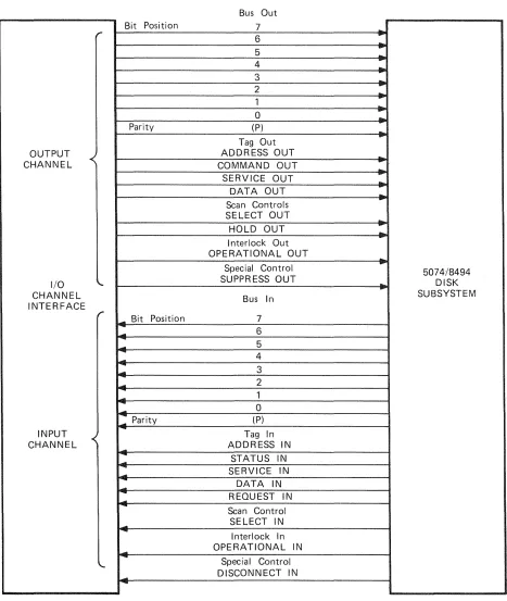
3.1. Interface Line Definition / 3-1 Bus Lines / 3-3
Selection Controls and Tag Lines / 3-3
3.2. Interface Signal Sequences / 3-6 Initial Selection Sequence / 3-6 Control Unit Busy Sequence / 3-7 Control Unit Initiated Sequence / 3-7 Data Transfer Sequence / 3-8
Termination Sequence / 3-8 Selective Reset Sequence / 3-8 Interface Disconnect Sequence / 3-9 System Reset Sequence / 3-9
Command Chaining / 3-9
4. Channel Command Description
4.1. Channel Command Set / 4-1 Types of Commands /4-1 Command Listing by Type / 4-2 Alphabetical Command Listing / 4-3
4.2. Control Commands / 4-3 No Operation (0316) / 4-4 Test I/O (0016 ) / 4-4 Define Extent (6316) / 4-5 Locate (43
16 ) /4-7
4.3. Read Commands / 4-12 Read (4216 ) / 4-12
Read Initial Program Load (0216) /4-13
4.4. Write Command / 4-15 Write (4116) /4-15
4.5. Search Commands (System 80 Only) / 4-16 Search Equal (0916) /4-17
Search Equal/High (0016) / 4-18
4.6. Sense Commands / 4-18
Sense Input/Output (0416) / 4-18 Sense Input/Output Type (E416 ) /4-19 Read and Reset Buffered Log (A416 ) / 4-20 Read Device Characteristics (6416) / 4-21 Device Reserve (B416 ) / 4-22
Device Release (9416 ) / 4-23
Unconditional Reserve (1416) / 4-24
5. Status Information
5.1. Status Conditions /5-1
5.2. Status Byte / 5-1
5.3. Initial Status / 5-3
5.4. Busy Status / 5-3
5.5. Ending Status / 5-4
5.6. Pending Status / 5-5
5.7. Contingent Connection / 5-6
5.8. Multiple Status Indications / 5-6
6. Sense Information and Error Logging
6.1. Sense Information Construction / 6-1
6.2. Sense Bytes 0 through 7/6-1 Byte 0/6-1
Byte 1 /6-2 Byte 2 / 6-3 Byte 3/6-4 Byte 4/6-4 Byte 5/6-4 Byte 6/6-5 Byte 7/6-5
Format 1 .. Device Equipment Check /6-6
Format 2 - Disk Control Unit Equipment Checks /6-7 Format 3 - Disk Control Unit Control Checks /6-7 Format 4 .. Uncorrectable Data Check /6-7
Format 5 .. Data Checks With Displacement Information / 6-8 Format 6 .. Usage Statistics Errors /6-8
6.4. Error Logging / 6-9 Usage Counters / 6-9 Error Counters / 6-10
7. Hardware Error Detection and Recovery Procedures
7.1. Error Conditions /7-1
Programming Errors or Unusual Conditions /7-1
Write Inhibited / 7-2
Alternate Space Exhausted / 7-2
Drive Offline or Not On System / 7-3
Bus Out Parity Error /7-3
Drive Equipment Check /7-3
Disk Control Unit errors /7-4
Data Check / 7-5
Service Overrun /7-6 Block Size Exception / 7-7
File Protected /7-7 Access Error / 7 .. 7
Error Counter or Usage Counter Overflow /7-8
Defective or Alternate Block /7-9
Disk Control Unit Offline / 7-9
7.2. System Recovery Actions /7-9
Recovery Action 1 / 7-10
Recovery Action 2 / 7-10
Recovery Action 3/7-11
Recovery Action 4/7-11
Recovery Action 5 / 7-11
Recovery Action 6/7 .. 12
Recovery Action 1/7-13
Recovery Action 8/7-14
Recovery Action 9/7-14
Recovery Action 10/7-15
Appendix A. Error Condition and Recovery Action Summary
Glossary
Index
Figures
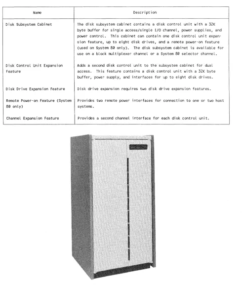
1-1. 5074/8494 Disk Subsystem / 1-2
1-2. Single-Access 5074/8494 Disk Subsystem Configuration / 1-7 1-3. Dual-Access 5074/8494 Disk Subsystem Configuration / 1-8
3-1. Input/Output Interface Lines / 3-2 3-2. I/O Interface Priority Selection /3-4
Tables
1-1. Subsystem Components and Features / 1-2 1-2. Subsystem Performance Characteristics / 1-3
3-1. Summary of Input/Output Interface Signals /3-4
4-1. Channel Command Set Listing by Type / 4-2 4-2. Channel Commands Arranged Alphabetically / 4-3 4-3. Define Extent Parameter Bytes / 4-6
4-4. Locate Command Parameter Bytes / 4-8 4-5. Device Characteristics Format / 4-21
5-1. Status Byte Bit Description / 5-2
1.
Introduction
This section describes the subsystem hardware components, characteristics, features, and configura tions.
1.1. Components and Features
The 5074/8494 disk subsystem (Figure 1-1) can operate on either a block multiplexer channel (5074-00) or a System 80 10/20 selector channel (5074-01). It is a freestanding subsystem with the following components and features. Table 1-1 provides a summary of the subsystem's major components and features.
Com pone nts ____________________________________________________________________ __
The disk subsystem includes a disk control unit and disk drives. Up to two disk control units and eight disk drives can be in the freestanding cabinet. The disk control unit con tains a 32K byte buffer to smooth variations in data transfer. The disk control unit can have one or two (optional feature) host I/O channel interfaces.
The disk drives have a formatted data capacity of 308 million bytes and an average access time of 22.6 milliseconds. An optional dual-access feature is available for connecting the disk drives to a second disk control unit.
Configurations _______________________________________________ _
A minimum subsystem consists of a single cabinet that contains a disk control unit and two disk drives. A maximum configuration consists of a single cabinet, two disk control units, and eight disk drives. Two disk drives is the minimum required when expanding the number of disk drives in the subsystem.
Storage Capacity
---The minimum subsystem (two disk drives) provides 606 million bytes of data storage on the block multiplexer channel subsystem and 616 million bytes of data storage on the selector channel subsystem. The maximum subsystem (eight disk drives) provides 2.42 billion bytes of data storage on the block multiplexer channel subsystem and 2.46 billion bytes of data storage on the selector channel subsystem.
1-2
Table 1-1. Subsystem Components and Features
Name
Disk Subsystem Cabinet
Disk Control Unit Expansion Feature
Description
The disk subsystem cabinet contains a disk control unit with a 32K byte buffer for single access/single I/O channel, power supplies, and power control. This cabinet can contain one disk control unit expan-sion feature, up to eight disk drives, and a remote power-on feature (used on System 80 only). The disk subsystem cabinet is available for use on a block multiplexer channeL or a System 80 selector channel.
Adds a second disk control unit to the subsystem cabinet for dual access. This feature contains a disk control unit with a 32K byte buffer, power supply, and interfaces for up to eight disk drives.
Disk Drive Expansion Feature Disk drive expansion requires two disk drive expansion features.
Remote Power-on Feature (System Provides two remote power interfaces for connection to one or two host
80 only) systems.
ChanneL Expansion Feature Provides a second channel interface for each disk control unit.
Figure 1-1. 5074/8494 Disk Subsystem
Characteristics
1.2.
Performance Characteristics
Table 1-2 summarizes the subsystem performance characteristics.
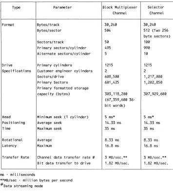
Table 1-2. Subsystem Performance Characteristics
UP-11627
Type Parameter
Format Bytes/track Bytes/sector
Sectors/track
Primary sectors/cyLinder Alternate sectors/cyLinder
Drive Primary cylinders
Specifications Customer engineer cyL inders Sectors/drive
Primary Sectors
Primary formatted storage capacity (bytes)
Head Minimum seek (1 cylinder) Positioning Average seek
Time Maximum seek
RotationaL Average Latency Maximum
Transfer Rate ChanneL data transfer rate #
Bit data transfer to drive
ms . miLLiseconds
**MB/sec - miLLion bytes per second #Data streami ng mode
Block MuLtiplexer Selector ChanneL Channel
30,240 30,240 504 512 (Two 256
byte sectors)
50 100
495 990
5 10
1215 1215
2 2
608,500 1,217,000 601,425 1,202,850
303,118,200 31.37,929,600 (67,359,600
36-bit words)
5 ms* 5 ms* 14.33 ms 14.33 ms 35 ms 35 ms
8.33 ms 8.33 ms 16.8 ms 16.8 ms
3 MB/sec.** 3 MB/sec.** 1.82 MB/sec. 1.82 MB/sec.
1.3. Subsystem Cabinet
The disk subsystem cabinet can contain up to two disk control units and up to eight disk drives. It also contains power supplies, a power control, and for the System 80 only an optional remote power on feature. The remote power on feature controls power to the cabinet from the host system.
A circuit breaker located at the rear of the disk subsystem cabinet provides control of the main AC input power.
1.4. Disk Control Unit
This subsection describes the disk control unit operational features.
Operation
The disk control unit operates at 3 million bytes per second in the data streaming mode, and at 1.82 million bytes per second in the interlock mode on a block multiplexer or selector channel.
Buffering
The disk control unit buffer synchronizes the difference in transfer rates between the disk drive and the I/O channel. The disk control unit transfers 64K byte blocks of data without overrun.
Features
---~---The disk control unit significant features are:
III Rota tional position sensing
III 32K byte speed matching buffer
II1II Error recovery operation
III Retry hard errors
III Power on confidence (PaC) test
III Two channel attachments per disk control unit
II1II Pari ty protection on all data paths
l1li Parity or check characters for all memory devices
Disk Drive Features
Error Checking
The disk control unit performs internal tests to check all hardware functions. The subsystem performs these tests automatically when powering up the subsystem. The operator can perform these tests from the operator's control panel.
1.5. Disk Drives
The disk drive is a random-access, fixed-media disk drive. It consists of a sealed module assembly and the required support electronics. These features provide write/read,
servo/motor control, and interface operations.
Track Format
The disk drive has 30,240 bytes per track divided into 50 sectors for the block
multiplexer channel, and 100 sectors for the selector channel. Each sector contains 603 bytes and a 90-byte end-of -track gap.
Reliability
---The disk drive has the following reliability features:
III A dedicated head landing zone outside of the data recording area
III A sealed module assembly with its own closed loop air filtration system that contains
the disk drive heads, media, and actuator
Availability ___________________________________________ _
The availability features for the disk drive include:
III Dual-access
III High-performance access to data at an average rate of 22.66 milliseconds
III Automatic recovery without operator intervention after AC power loss
Maintainability
---The main taina bili ty f ea tures for the disk drive include:
III No required scheduled maintenance other than cleaning or replacement of air filters
III Built-in self test during the power up sequence
III Offline diagnostics run from a Status/Control Panel
II Automatic carriage lock/unlock on power down/up
1.6. Configurations
The 5074/8494 Disk Subsystem can be configured as a single-access subsystem or as a dual-access subsystem. Either configuration is available for use on a block multiplexer channel or a System 80 selector channel.
Single-Access Disk Subsystem
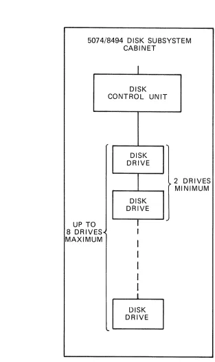
---~---A single-access configuration (see Figure 1-2) provides the host with one access path to any disk drive in the subsystem. This configuration consists of one disk control unit and two to eight disk drives.
Dual-Access Disk Subsystem
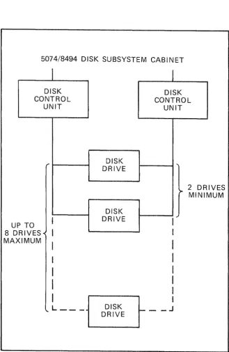
The dual-access configuration (see Figure 1-3) has two access paths to each disk drive from the host system. This provides simultaneous operation on any two disk drives in the subsystem. A minimum configuration of a dual-access 5074/8494 Disk Subsystem consists of two disk control units and two to eight disk drives in one subsystem cabinet.
Additional Features
Additional expansion features include:
l1li Remote Power-On Feature (Used on System 80 only)
This feature provides two Federal Information Processing Standard (FIPS) 61 remote power interfaces that connect to one or two host systems.
l1li Channel Expansion
This feature provides attachment to one or two disk control units to a second I/O channel.
II Channel Port Expander
'-6
This feature provides two additional channel ports to one disk control unit. Only one feature can be used on a disk control unit.
UP-11627
Single-Access Configuration
5074/8494 DISK SUBSYSTEM CABINET
0
UP T 8 DRIV MAXIM
ES· UM
I
DISK CONTROL UNIT
DISK DRIVE
DISK DRIVE
I
..
t
I
I
I
I
I
I
DISK DRIVE
...
2
~ MI DRIVES NIMUM
Figure 1-2. Single-Access 5074/8494 Disk Subsystem Configuration
1-8
5074/8494 DISK SUBSYSTEM CABINET
I
DISK CONTROL
UNIT
P TO
U
8 0
MA RIVES-< XIMUM ,..
I
I
I
I
I
I
I
'- L _ _ _
DISK DRIVE DISK DRIVE DISK DRIVE
I
DISK CONTROL UNIT ...2 DR
>- MINI IVES MUM
I
~I
I
I
I
I
I
I
_ _ JFigure 1-3. Dual-Access 5074/8494 Disk Subsystem Configuration
2.
Subsystem Operations
This section describes control unit selection and addressing, disk drive addressing, and the track format.
2.1. Interface Types and Features
The 5074/8494 disk subsystem is a fixed-block rotating mass storage subsystem. The subsystem can attach to a block multiplexer I/O channel or a System 80 10/20 selector I/O channel. The disk subsystem uses the Federal Information Processing Standards (FIPS) 60-2 I/O channel interface. The FIPS interface is the communication link between the host I/O channel and the disk subsystem. The host system performs the following functions through the I/O channel:
III Addresses the subsystem and disk drives
III Transfers the channel commands (see Section 4) to the subsystem
III Reads and writes data from and to the subsystem
III Receives the status indications (see Section 5) and sense information (see Section 6)
from the subsystem
The subsystem consists of one or two disk control units connected to one or two I/O channels. The disk control unit can control two to eight disk drives.
2.2. Control Unit Selection
More than one I/O channel interface can access each disk control unit. If channel x
selects a control unit that is already in use by channel y, the control unit presents busy status to channel x. If both channels select the same control unit, it may delay the selection sequence on one channel until the requirements of the other channel are determined. Then, the system either continues the selection sequence or indicates busy status on the channel that was delayed.
2.3. Control Unit Addressing
The factory assigns an address to each control unit with back panel jumpers. A customer engineer can change the address at the customer sites. The addresses follow.
For block multiplexer channel systems:
11\1 First disk control unit - 0, 2, 4, 6
11\1 Second disk con trol unit - I, 3, 5, 7
For System 80 10/20 selector channel systems:
III First disk control unit - 8, A, C, E
ilII Second disk control unit - 9, B, D, F
2.4. Disk Drive Addressing
The factory sets the disk drive addresses. These addresses are from the top to the bottom of the cabinet, 0 through 7. An opera tor or a customer engineer can change the addresses by pressing the ADDR (logical address) switch on the disk drive operator's panel until the desired address is reached.
Track Format
Sectors make up the format of each track. Each sector is 603 bytes long, and there are a total of 50 sectors in each track. A one-to-two correspondence exists between sectors for block multiplexer channel systems and System 80 selector channels. Physical sector marks def ine the start of each sector. In the description that follows, the term sector refers to a logically addressable element starting at zero and ending at the maximum for the entire disk. The term sector refers to the physical partitioning of a track starting at sector zero and ending at sector 49.
Disk Capacity
The disk drive has 1217 cylinders and 10 heads (cylinders 1215 and 1216 are customer engineer cylinders). The following disk capacities are based on 512 byte data fields.
Sectors per track
Ill! Sectors per cylinder
l1li Alternate sectors per cylinder
Sectors per device
Primary sectors per device
Formatted storage capacity in bytes
50/100*
500/1000*
5
608,500/1,217,000 *
601,425/1,202,850 *
303,118,200/307,929,600
* Items marked with an asterisk are capacities for System 80 10/20 systems only.
*
Track Format
Sector Definition
---A sector format contains the following fields:
III Three gap fields
III An identification (ID) field
III Two error correction code (ECC) fields
III A data field
Each sector begins and ends with a sector (index) mark and is 603 bytes long. Gaps separate the ID field and data field. An ECC field follows each of these fields. The sector format is:
Sector Format - 603 bytes
Gap 1 ID ECC Gap 2 Data ECC Gap X
30 bytes 6 bytes 4 bytes 34 bytes 512 bytes 7 bytes 10 bytes
Gap Fields
The gap fields allow the control unit time to set up the hardware and microcode
parameters. These parameters are necessary for system operatation on the next ID or data field.
Gap 1 is a variable length field (30 bytes maximum). The length depends on whether the ID field that follows is to be moved to a void a track defect. The Gap 1 format is:
Gap 1 Format - 30 bytes
Zeros Zeros Zeros Sync 2 bytes A 15 bytes* 12 bytes 1 byte
Index Mark or Sector Mark
*These n umbers are for ID in normal position.
For displaced ID: A is 113, Gap 1 is 158
For extended displacement: A is 271, Gap 1 is 286
Gap 2 contains a midgap write splice (write turn on or turn off point) to update data field write operations that follow. The Gap 2 format is:
Gap 2 Format - 34 bytes
Zeros Zeros Zeros Zeros Sync 2 bytes 17 bytes 2 bytes 12 bytes 1 byte
Gap X is for end of sector tolerance. The Gap X format is:
Gap X Format - 10 bytes
Zeros 2 bytes
Identification (ID) Field
Zeros 8 bytes
The ID field contains the physical address of the sector and the address of any assigned alternate sector. The ID field format is:
2-4
or Nonassigned Alternate ID Field Format - 6 bytes
Byte 0 Byte 1 Byte 2
0
Physical Fl ags 00 Physical Cyl Low Cyl Hi gh 123 4 5 6 7 012
~6.
e
ill
lB:t~
05 . Extended displacement ' - - - - 4 - Displaced
' - - - 3 - At ternate on cyl inder ' - - - 2 - Alternate ass i gned
- Alternate sector ' - - - 0 - Defective sector
Physical Head
3
4 5 6 7Byte 3
Sector
NOTE: Byte 0, bit 0 is the most significant byte and bit.
Assigned Alternate ID Field Format - 6 bytes
Byte 0 Byte 1 Byte 2 Byte 3 Physical
I
SectorFlags 00 Physical Cyl Low cyl Hi9h
l
offset Defective defined above 0 1 2 3 4 5 6 7 Cyl i nder Low
Byte 4 Byte 5 Alt Cyl Alt Sector Alternate Cyl High Offset
Low 012
13
4 5 6 7~
These bytes are zero in~
nonassigned alternate.Byte 4 Byte 5 Def cYllDefective
e
H: g: 13 :e;d6 7
Defective Sector
Track Format
The disk control unit uses the physical cylinder, head, and sector to verify positioning. The flag byte (byte 0) defines the type of sector, whether it's a defective sector, and whether an alternate sector has been defined. Flag bits 0 and 1 are defined below:
Bits 0 and 1
o
01 0
o
11 1
Sector Definition
Primary
Defective primary Alternate
Defective alternate
III Bit 2 indicates the flagged alternate sector is assigned to a defective primary. A
def ecti ve al terna te cannot be assigned.
III Bit 3 is adjusted in the defective primary when the alternate is assigned. If set, the
disk control unit does not cause accessor motion to locate the al terna teo
III Bit 4 indicates that the ID is written in the displaced position
III Bit 5 indicates the extended displaced position. If bit 5 is set, bit 4 is don't care. If
either bit 4 or bit 5 is set then bit 0 must be set.
The alternate sector offset is the displacement from the start of the alternate area on that cylinder to the alternate sector.
Data and ECC Fields
The data field is 512 bytes long and is followed by 7 ECC bytes. Application programs that use normal read and write commands use the data field. The ECC field can correct error bursts up to 11 bits long. The data field format is:
Data Field Format - 512 bytes + 7 ECC bytes
Track Definition
Data 512 bytes
ECC 7 bytes
---A track contains 50 equal sectors aligned on physical sector boundaries. The track also contains a 90 byte end-of-track gap used for head switching when the disk performs multiple track operations. The track sector format is:
Track Sector Format - 50 sectors
. - - - r - - - r - - - , - - - , . - - - , - - - ,
Sector Sector n n+1
Sector n+2
Sector
n+47
'----_ _ _ _ - ' - -_ _ _ _ _ - ' - -_ _ _ _ _ _ _ _ _ _ _ _ _ _ --'--_ _ _ _ _ ----L _ _ _ _ _ _ --'---_ _ _ _ _ ---J
Cylinder Definition _ _ _ _ ..,...,. _ _ _ _ _ _ _ _ _ _ _ _ _ _ _ _ _ _ _ _ _ _ _ _ _ _ _ _ _
The disk drive has 10 heads and 1217 cylinders. Each cylinder has 495 primary sectors and 5 alternate sectors as shown in the formats below.
The first sector in the even numbered cylinders is in sector 0 of head 0, and in sector 25 of head 0 in the odd numbered cylinders. This arrangement allows a single track to occur when a disk encounters a cylinder boundary during a multiple sector operation without losing an en tire disk revolution.
The five alternate sectors start after the last logical sector on the cylinder. The last 20 logical sectors on an odd numbered cylinder start at sector 0 on head O.
The even and odd numbered cylinders formats are:
Even Numbered Cylinders Format
Sector 0 Head 0
Head 1
Head 2
Head 8
Head 9
Index
2-6
5 Alternate Sectors
Sector 45 Index
Track Format
Odd Numbered Cylinders Format
Head 0 5 Alternate Sector 0
Head 1
Head 2
Head 8
Head 9
Track defects are handled using alternate sectors. There are five alternate sectors for each cylinder. The alternate sectors need not be on the same cylinder as the defect if all alternate sectors on that cylinder are already assigned.
The format defective sector operation of the locate command searches for an unassigned alternate sector on the cylinder of the defective sector. Alternate sectors are assigned in ascending order from sector 45, head 9 on even numbered cylinders. On odd numbered cylinders, alternate sectors are assigned in ascending order from sector 45, head O. If there is no available alternate sector on the cylinder, the search continues on the
defective sector's cylinder +1, then -1, then +2, then -2. This scheme minimizes accessor motion when a read or write command encounters a defective sector.
(
3.
Channel Input/ utput Operations
This section describes the channel interface signals and signal sequences.
3.1. Interface Line Definition
The input/output (I/O) interface lines (Figure 3-1) provide the disk subsystem with a common information format and signal sequence. The disk control unit decodes the commands received from the host. Then, the disk control unit interprets the commands for the device and provides the signal sequences to execute the operation.
Except for signals that establish priority among disk control units, all interface signals travel over multiplex lines. Only one disk control unit at a time logically connects to the interface. After selection, it remains logically connected to the interface until one of the following operations occur:
III The disk control unit transmits the required information
III The disk control unit receives the required information
III The channel signals the disk control unit to disconnect
The signals transmitted over the interface are interlocked with the corresponding responses, making the interface applicable to a wide variety of data rates.
Each disk control unit contains a wired address that indicates its interface address. Two disk control units on the same interface cannot have the same address. To begin an I/O operation, the channel must transmit the address of the desired disk control unit.
The disk control unit converts interface line sequences and coded commands to the control functions necessary to operate and establish communications between the disk con trol unit and the interface.
Bus Out
Bit Position 7
...
r
6
....
...-5 ...
4
-
....3 ...
2
...
..
1
..
...
0
-
....
Parity (P)
-...
Tag Out
OUTPUT ADDRESS OUT ....
CHANNEL COMMAND OUT
-.
...
SERVICE OUT
...
DATA OUT-
...-Scan Controls
SELECT OUT
-HOLD OUT
-
....
I nterlock OutOPERATIONAL OUT ...
Special Control
....
5074/8494I/O
""
SUPPR ESS OUT..
...
DISKCHANNEL Bus In SUBSYSTEM
INTERFACE
r _ Bit Position
7
....
.-... 6
...
54
--l..
-
3-
2...
1...
-
0: Parity (P)
INPUT Tag In
CHANNEL
..
ADDRESS IN....
STATUS IN
-
-
-
SERVICE IN--
DATA IN....
--
REQUEST IN....
Scan Control SELECT IN
....
...
I nterlock In OPERATIONAL IN
-
-
Special ControlDISCONNECT IN ....
-Figure 3-1. Input/Output Interface Lines
I/O Interface Lines
Bus Lines
---The bus lines consist of a set of nine bus-out and nine bus-in lines. Each group of nine consists of eight data lines and one parity line.
Except for control signals, all data transmitted between the host and the disk subsystem travels on the bus lines. Any signal the channel provides is common to all disk control units. However, only one disk control unit at a time can logically connect to the channel.
The bus-out lines carry addresses, commands, and data information from the channel to the disk control unit. The bus-in lines carry addresses, data, status, and sense
information from the disk control unit to the channel. A simultaneous signal on the appropriate control line indicates the type of information contained on the bus-out and bus-in lines.
Bit position 7 is the low-order value of a byte on a bus. Bit position 0 is the high-order value, with intervening bits in descending order. When it is necessary to transmit less than eight data bits, the bits must be in the highest numbered adjoining bit positions of the bus. All unused lines must be low numbered lines (bit position 0 and adjoining bit positions). The parity bit must always be the result of odd parity.
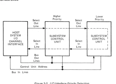
Selection Controls and Tag Lines
When an operation starts, the channel applies a signal to the select-out line. The SELECT OUT signal passes serially through all disk control units in order of priority. The
SELECT OUT signal travels to the disk subsystem with the highest priority. The selection priority is (1) all control units on the select out lines in order of attachment from the channel to the end of the string of control units, followed by (2) all control units on the select in lines in order of attachment from the end of the string to the channel (see Figure 3-2.).
If the address is not that of the addressed unit or the unit does not require service, the SELECT OUT signal travels to the disk subsystem with the next highest priority. This operation continues until the SELECT OUT signal travels to the addressed or requesting disk subsystem. When the disk subsystem accepts the address or is the requesting unit, it captures the interface by applying a signal to the operational-in line. This signal inhibits passage of the SELECT OUT signal to the next lower priority disk subsystem.
Normally, the disk subsystem retains control of the interface for a short interval
(execution of immediate commands or transfer of a single byte of data) and relinquishes control by passing the SELECT OUT signal to the next lower priority unit. During the next initiation of the SELECT OUT signal, the operation is repeated. That is, another da ta byte is transferred. This process is repeated un til the transfer operation is complete and the subsystem notifies the channel of this status.
If none of the disk control units recognize the address or require servicing, the lowest priori ty disk control unit sends the SELECT IN signal to the channel.
Select Out Line
..
...
HOST SYSTEM
I/O
CHANNEL Select INTERFACE In
Line
-Bus
~
I
OutLines Control Unit Address Bus In Lines
Higher Priority - - -SUBSYSTEM CONTROL UNIT - - - - -
-1
..."
...
-Select Out Line
..
...
Select In Line Lower Priority- - - 1 I
SUBSYSTEM: CONTROL
UNIT I I
_ _ _ _ _ _ J
r
Figure 3-2. I/O Interface Priority Selection
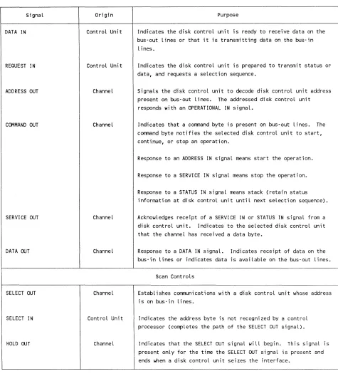
Ta bIe 3-1 gives the signal name, its origin, its purpose, and the effect of each for each group of lines.
Signal
ADDRESS IN
STATUS IN
SERVICE IN
3-4
Table 3~1. Summary of Input/Output Interface Signals
Origin
Control Unit
Control Unit
Control Unit
Purpose
Tag Lines
Indicates that the address of the currently selected disk control unit requiring service is on bus-in lines.
Indicates that a status byte is present on bus-in lines.
Signals the channel when the selected disk control unit is ready to transmit or receive a byte of information. The type of information depends on the operation.
The channel responds with a SERVICE OUT, COMMAND OUT, or an ADDRESS OUT (during a disconnect) signal.
SignaL
DATA IN
REQUEST IN
ADDRESS OUT
COMMAND OUT
SERVICE OUT
DATA ooT
SELECT ooT
SELECT IN
HOLD ooT
UP-11627
I/O Interface Lines
Table 3~1. Summary af Input/Output Interface Signals (cant)
Origin
Control Unit
Control Unit
ChanneL
Channel
Channel
ChanneL
ChanneL
Control Unit
Channel
Purpose
Indicates the disk control unit is ready to receive data on the bus-out lines or that it is transmitting data on the bus-in
lines.
Indicates the disk control unit is prepared to transmit status or data, and requests a selection sequence.
Signals the disk control unit to decode disk control unit address present on bus-out lines. The addressed disk control unit responds with an OPERATIONAL IN signal.
Indicates that a command byte is present on bus-out lines. The command byte notifies the selected disk control unit to start, continue, or stop an operation.
Response to an ADDRESS IN signal means start the operation.
Response to a SERVICE IN signal means stop the operation.
Response to a STATUS IN signal means stack (retain status information at disk control unit until next selection sequence).
Acknowledges receipt of a SERVICE IN or STATUS IN signal from a disk control unit. Indicates to the selected disk control unit that the channel has received a data byte.
Response to a DATA IN signaL. Indicates receipt of data on the bus-in lines or indicates data is available on the bus-out lines.
Scan Controls
Establishes communications with a disk control unit whose address is on bus-in lines.
Indicates the address byte is not recognized by a control processor (compLetes the path of the SELECT OUT signaL).
Indicates that the SELECT OUT signaL wiLL begin. This signaL is present onLy for the time the SELECT ooT signaL is present and ends when a disk controL unit seizes the interface.
Table 3-1. Summary of Input/Output Interface Signals (cont)
Signal Origin Purpose
Interlocks
OPE RA TI ONAl IN Control Unit Indicates that a disk control unit was selected and will be present for the entire period of time that data is being transmitted to the channel.
OPERATIONAL OUT Channel Allows operations between the disk control units and channel. When this signal is not present, all lines to the channel are made inoperable.
Special Controls
SUPPRESS OUT Channel Informs the disk control units not to generate a service request in an attempt to seize the interface. This signal suppresses any subsequent data or status transfer.
DISCONNECT IN Control Unit Indicates to the channel that the selected disk control unit has detected a malfunction that prevents it from signaling properly over the I/O interface.
3.2. Interface Signal Sequences
Each I/O operation between the host I/O channel and the disk control unit requires a certain sequence of events to occur that the I/O channel controls. A system of
interlocking inquiry and response signals through signal lines (see Figure 3-2) controls an orderly flow of data between the channel and the disk control unit.
Interface signal sequences control the transfer of information between the channel and the disk control unit. The following subsections describe these sequences.
The initial selection sequence initiates an I/O operation. When the disk control unit is the output device, this sequence activates a group of signals in a particular sequence. Initially, the channel places the disk control unit address on the bus-out lines. After a predetermined delay, the channel raises the ADDRESS OUT signal. The ADDRESS OUT signal causes the disk control unit control circuit to compare the address on the bus-out lines with its own assigned address. The disk control unit can respond only if parity is correct.
Interface Signal Sequences
After the address comparison is complete, the channel raises the SELECT OUT signal. It then waits for a response from the disk control unit. Disk control unit responses are: SELECT IN, STATUS IN, and OPERATIONAL IN signals.
The disk control unit busy sequence occurs when a disk control unit is addressed during an initial selection sequence and anyone of the following conditions is true.
III The disk control unit is busy executing a previously initiated command.
III The disk control unit is erasing a track after a format write.
III The channel initiated an interface disconnect sequence, and either the operation has
not completed or it has not accepted ending status.
III The disk control unit is performing a command retry function on another channel
interface.
III The disk control unit is holding a contingent connection for another channel or for a
disk drive other than the one addressed.
III Stacked status (other than control unit end or device end) for another channel or for
a disk drive, other than the one addressed, is being held in the disk control unit.
III The disk control unit is performing a timing countdown for another channel
interface.
Control Unit Initiated Sequence
When the disk control unit is not currently assigned to the interface, it can request a selection sequence. The disk control unit raises the REQUEST IN signal to alert the channel of the need to communicate for the following conditions:
III The disk control unit is not busy.
III The ADDRESS OUT signal is not active on the channel interface.
II The status pres en t in the disk control unit is not suppressed.
When its incoming SELECT OUT signal rises and the ADDRESS OUT signal is inactive, the disk control unit captures the interface. The disk control unit then, performs the following operations:
II Blocks the propagation of the SELECT OUT signal
II Raises the OPERA.TIONAL IN signal
Places a device address on the bus-in lines
II Activates the ADDRESS IN signal
The channel acknowledges receipt of the device address by activating the COMMAND OUT signal. This allows the disk control unit to drop the device address and the ADDRESS IN signal. The disk control unit is now logically connected to the channeL remains connected until it drops the OPERATIONAL IN signal.
Data Transfer Sequence __________________________________________________________ __
Data byte transfers occur on a request-acknowledge basis (that is, service in and service
ou t). For input data transfers, the connected disk control unit the
opera tions:
II Places an input data byte on the bus-in lines
Activates the SERVICE IN signal
Waits for a SERVICE OUT or COMMAND OUT signal response from the channel
A SERVICE OUT response indicates acceptance of the data byte information. COMMAND OUT response indicates rejection of the data byte information.
For output data transfers, the connected disk control unit activates the SERVICE IN and waits for a SERVICE OUT response from the channel. A SERVICE OUT response indicates that the channel received the data byte inf orma tion.
Termination
Either the channel or the disk control unit ends an operation. The channel an end
of transfer (stop) by responding to a SERVICE IN signal with a COMMAND OUT
When the disk control unit ends an operation, regardless of the reason, it transmits the
status byte to the channel unless the STATUS IN signal has been a
selection sequence presents the status byte to the channel. When the disk control unit is connected to the channel, it places the status byte on the bus-in lines and raises the ST A TUS IN signal.
Selective Reset Sequence
---The selective reset sequence disconnects the disk control unit from the interface and resets the status. The disk control unit performs the following operations after this sequence:
Ii Clears the status register
Interface Signal Sequences
ill Stops any data transfer sequence in progress
ill Immediately disconnects from the interface
However, any command in progress may be completed if the selective reset occurred after the channel end status was stored in the status register.
If the disk control unit receives the selective reset sequence during a data transfer sequence, the disk control unit performs the following operations:
ill Ends a data transfer
1'1 Presents unit check status alone in the next initial selection sequence (next start I/O) 1'1 Constructs Format 3 sense information
Interface Disconnect Sequence
Opera tion of the interface disconnect sequence is similar to the selective reset sequence except that the status register is not cleared. Holding the ADDRESS OUT signal high while the SELECT OUT signal is low causes the channel to force the disk control unit to drop the OPERATIONAL IN signal and release the interface. The channel maintains this condition until the OPERATIONAL IN signal drops, causing the channel to drop the ADDRESS OUT signal which completes the sequence. Operations in the disk control unit proceed normally except that the disk control unit does not transfer any data bytes. The disk control unit may initiate a selection sequence to transmit status condition.
System Reset Sequence
---The system reset sequence causes the disk control unit control section to enter a cleared state in which the disk control unit can accept any valid command. A system reset sequence occurs when the channel is powered up. The following conditions occur in this operation:
1'1 The channel holds the OPERATIONAL OUT and SUPPRESS OUT signals low
concurrently
1'1 The disk control unit is reset
ill The OPERATIONAL IN signal drops
Command Chaining
Command chaining indicates that another command for the current disk drive immediately follows device end status. This indication occurs as long as no unusual conditions have occurred during the current operation. The SUPPRESS OUT and
SERVICE OUT signals in response to the STATUS IN signal indicate command chaining.
such as unit in the channeL
A multidevice disk control unit
1. Reset the
2. Present control
If command
control meantime
command is
must be a reselection of the
disk
response to
command is not
nanoseconds before the rise of the STATUS IN ,ah,eA<>A-A.
4.
Channel Command Description
This section describes the channel command set for both the block multiplexer channel and the System 80 Models 10/20 selector channel.
4.1. Channel Command Set
This subsection shows the types of commands, and lists them by type in Table 4-1 and alphabetically in Table 4-2.
TypesofCommands ____________________________________________________________
-The channel command set consists of the following types of commands:
III Control
III Read
III Write
III Search (System 80 Model 10/20 selector channel only)
III Sense
Subsection 4.2 describes each command. The description for each command contains the following information:
III Command name and hexadecimal code
III Functional description of the command
III Parameters for the command
III Error conditions that can occur during command operation
iii Chaining requirements for the command
III Status indications that may be presented for the command
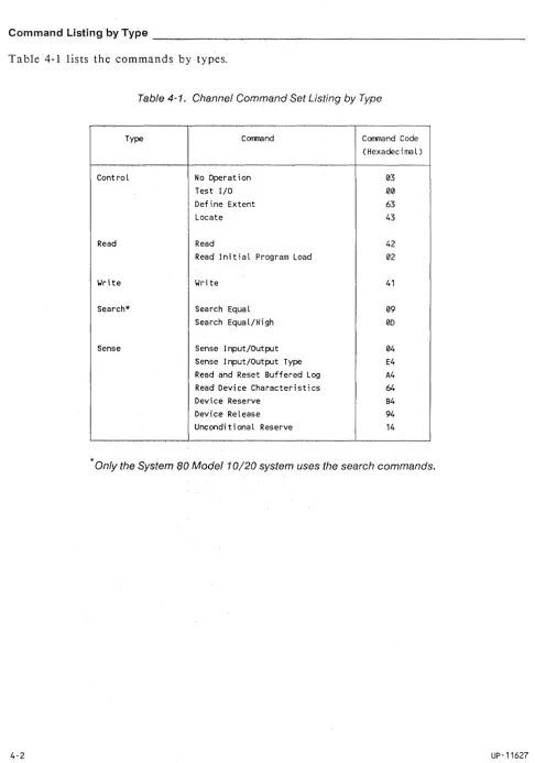
Table 4-1 lists the commands by types.
Table 4-1. Channel Command Set Listing by Type
Type Corrmand Corrmand Code
(Hexadeci rna l )
Control No Operation 03
Test I/O 00
Define Extent 63
Locate 43
Read Read 42
Read Initial Program Load 02
Write Wri te 41
Search* Search Equal 09
Search Equal/High 00
Sense Sense Input/Output 04
Sense Input/Output Type E4 Read and Reset Buffered Log A4
Read Device Characteristics 64
Device Reserve B4
Device Release 94
Unconditional Reserve 14
* Only the System 80 Model 10/20 system uses the search commands.
Types of Commands
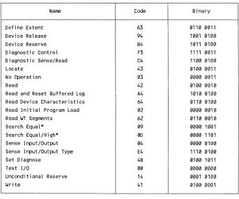
Ta ble 4-2 lists the commands alphabetically.
Table 4-2. Channel Commands Arranged Alphabetically
Name Code Binary
Define Extent 63 0110 0011
Device Release 94 1001 0100
Device Reserve B4 1011 0100
Diagnostic Control F3 1111 0011
Diagnostic Sense/Read C4 1100 0100
Locate 43 0100 0011
No Operation 03 0000 0011
Read 42 0100 0010
Read and Reset Buffered Log A4 1010 0100 Read Device Characteristics 64 0110 0100 Read Initial Program Load 02 0000 0010
Read WT Segments 62 0110 0010
Search Equal* 09 0000 1001
Search Equal/High* 0D 0000 1101
Sense Input/Output 04 0000 0100
Sense Input/Output Type E4 1110 0100
Set Diagnose 4B 0100 1011
Test I/O 00 0000 0000
Unconditional Reserve 14 0001 0100
Write 41 0100 0001
* Only the System 80 Model 1 0/20 system uses the search commands.
4.2.
Control Commands
The control commands transfer only control information to the disk subsystem. These commands do not transfer stored data to or from the disk subsystem. This information can include subcommands that specify certain actions that are performed by the disk control unit or disk units, or other parameters required by the command.
No Operation (03
16) _ _ ~ _ _ _ _ _ _ _ _ _ _ _ _ _ _ _ _ _ _ _ _ _ _ _ _ _ _ _
The no operation command is an immediate command; it causes no action at the
addressed device. It is used to maintain the channel connection during I/O operations.
Parameters
There are no parameters passed by this command.
Error Conditions
The disk control unit detects equipment check conditions.
Chaining Requirements
There are no chaining requirements specified for this command.
Status Indications
The status indications for the no operation command are: channel end and device end presented in initial status.
Test I/O (0016 ) _ _ _ _ _ _ _ _ _ _ _ _ _ _ _ _ _ _ _ _ _ _ _ _ _ _ _ _ _ _
The test I/O command releases the addressed I/O path of pending status information.
Parameters
There are no parameters passed by this command.
Error Conditions
The disk control unit detects equipment check conditions.
Chaining Requirements
There are no chaining requirements specified for this command.
Status Indications
This command normally presents an all-zero status byte. The initial status indication contains any stacked or pending status.
Control Commands
Define Extent (63
16 ) _ _ _ _ _ _ _ _ _ _ _ _ _ _ _ _ _ _ _ _ _ _ _ _ _ _ _ _ _ ~
The define extent command defines:
iii Opera tions allowed by following chained commands
iii The size of data blocks in bytes (512 bytes for Series 1100 and 256 bytes for System
80)
III A contiguous extent of data blocks that can be accessed by subsequent chained
commands
III A relative displacement in data blocks from the start of a data set to the extent.
Subsequent chained commands may access this relative displacement.
Parameters
This command transfers 16 bytes of parameters from the channel to the disk control unit. The disk control unit retains the define extent parameters until the end of command chaining. Table 4-3 describes each define extent parameter byte.
Error Conditions
The following error conditions can occur during a define extent command operation:
III Insufficient parameter bytes were transferred
iii In valid parameters were transferred
iii Another define extent command in the chain preceded the command.
iii Equipment check conditions detected by the disk control unit.
Chaining Requirements
A define extent command must not be preceded by another define extent command in the same chain.
Status Indications
The following are status indications for the define extent command:
iii Initial status is usually zero.
iii Channel end and device end are presented after the parameters were transferred to
the disk control unit and checked for validity.
iii Error conditions end the command with channel end, device end, and unit check
sta tus.
Table 4-3. Define Extent Parameter Bytes
Byte NU1lber and Name
Byte 0 " Mask Byte
Byte 1 reserved
Bytes 2 and 3 - Block size
Bytes 4 thru 7 - Physical Extent Offset
Bytes 8 thru 11 First Extent Displacement
Bytes 12 thru 15 - Last Extent Displacement
4·6
Description
The mask byte determines which operations are inhibited in subsequent chained commands. The bit functions are:
Bits
0, 1 - 1313
- 01
10
11
2, 3 - 1313
4
5
- 1313 • 131
- 130 01
6, 7 - 1313
Function
Inhibit format write operations Inhibit all write operations Invalid, must not be used Permit all write operations
Must be 1313 or parameters are invaLid
Indicates data area
Indicates CE area, for maintenance use only
Inhibit diagnostic commands ALlow diagnostic commands
Must be 013 or parameters are invalid
Byte 1 must be s~t to zero or the parameters are invalid.
The block size bytes define the Logical block size. This disk subsystem block size is 5134 bytes for block multiplexer channel systems and 256 bytes for the System 80 selector channel.
The physical extent offset bytes define the offset, from block zero of the logical device, of the first block of the extent that permits access by subsequent chained locate commands.
The first extent displacement bytes define the relative displacement, in blocks, from the beginning of the data set to the first block of the extent that permits access by subsequent chained commands.
The last extent displacement bytes define the relative displacement, in blocks, from the beginning of the data set to the last block of the extent.
The extent begins at the first extent displacement and ends at the last extent displacement.
(
Control Commands
Locate (4316 )
The locate command defines the location and amount of data processed by an
immedia tel y following chained read or write command. It positions the device to the first data block processed. This command does not transfer recorded data.
In the System 80, the locate command may use the locate disconnect mode (operation code bit 3) of operation to pre-position the device to the addressed block. After device
positioning starts, the disk control unit presents channel end status. This allows the channel to become available to start other operations. The channel performs a device reserve command on the device to prevent another path from modifying the device position. After device positioning is completed, the disk control unit presents device end status. The implicit reserve is reset on any subsequent I/O operation for the device on the path that caused the initial reserve.
Parameters
The locate command transfers eight bytes of parameters from the channel to the disk con trol unit. Table 4-4 defines the locate command parameter bytes.
Error Conditions
The following errors can occur during a locate command operation:
III Insufficient parameter bytes were transferred
III In valid parameters were transferred
III The command was not preceded by a read initial program load or a define extent
command in the command chain
III The command specifies a write operation and the device is write protected
III Data, access, or other device related errors when the command specifies format
def ecti ve block
III Equipment check conditions detected by the disk control unit
Chaining Requirements
A locate command must be preceded by a read initial program load or a define extent command in the same command chain, or the disk control unit rejects the locate
command. A status indication of channel end, device end, and unit check is presented.
Byte NUTlber and Name
Byte 0 - Operation Code
4-8
Table 4-4. Locate Command Parameter Bytes
Descri pt i on
The operation code specifies the type of operation performed:
I Block multiplexer channel modifier bits (0-3):
Bits 0 - 3 are reserved and must be zero or the command will be ended with device end and unit check status.
I System 80 selector channel modifier bits (0-2):
Bits 0 - 2 are reserved and must be zero or the command will be ended with device end and unit check status.
• System 80 selector channel modifier bit (3):
Modifier bit 3 indicates a locate disconnect operation.
• Operation code bits (4-7):
Bits 4 - 7 define the following operations:
Value Operation
Format defective block Wri te data data Write and check data Read replicated data Read data
0100 0001 0101 0010 0110
0111 Search data and read data (System 80 selector channel only)
Any other values are invalid and cause the command to end with channel end, device end, and unit check status.
Data transfers between the channel and disk subsystem associated with these operations do not occur during the execution of the locate command, but are initiated by an immediately-following chained read, write, or search (System 80 only) command.
A description of the operations specified above follows:
• Format defective block (0100):
The format defective block operation operates on only one Logical block (p~ysical sector in System 80). This operation causes the disk control unit to flag the logical block (physical sector in System 80) at the address specified as defective by bytes 4 through 7. The disk control unit assigns an alternate logical sector and establishes
UP-11627
Control Commands
Table 4-4. Locate Command Parameter Bytes (cant)
Byte Number and Name Description
appropriate pointers so that the specified alternate sector is accessed whenever subsequent commands attempt to access the sectors specified by bytes 4 through 7. If all alternate space is used, the disk control unit presents unit check and device end status, and, if not already presented, channel end status.
If the mask specified in the Define Extent command inhibits format write operations, or if the device is in read-onLy mode, the locate command is ended with channel end, device end, and unit check status.
If an unused alternate block (sector for System 80) is located, the disk control unit saves the aLternate block (sector for System 80) pointer and initiates access to the defective block (sector for System 80) specified in bytes 4 through 7 of the parameters, verifies the correct positioning, and formats the block (sector for System 80) identification with the defective flag bit on and the appropriate block (sector for System 80) pointer.
Format defective block operates on only one logical sector. During a format defective block operation, there is no data transfer between the channel and the disk control unit. The disk control unit
internally generates all written data. Only ID areas of the defective and alternate Logical sectors are written. After the format defective block operation, a locate command that specifies a write data opera-tion is issued to write the data field of the logical block.
Write Data (0001): This operation code prepares the disk control unit to write one or more blocks of data. The number of blocks to be written is specified in the block count parameters (bytes 2 and 3) of the locate command. If the mask specified in the define extent command inhibits all write operations, or if the device is locally set in read-only mode, the locate command is ended with channel end, device end, and uni