PV Interfaced Grid Connected PBT Based
DSTATCOM for Real and Reactive Power
Control
N. Raghava1, T. Praveen Kumar 2, Dr K. Sumanth3
P.G. Student, Department of Electrical &Electronics Engineering, Sreenidhi Institute of Science and Technology,
Hyderabad, Telangana, India1
Associate Professor, Department of Electrical &Electronics Engineering, Sreenidhi Institute of Science and
Technology, Hyderabad, Telangana, India2
Principal and Professor, Department of Electrical &Electronics Engineering, Sreenidhi Institute of Science and
Technology, Hyderabad, Telangana, India3
ABSTRACT: In this paper Fuzzy logic controller for PV Interfaced Grid connected PBT (Power Balance Theory) based DSTATCOM (Distribution Static Compensator) for real and reactive power control is elaborated and implemented using ‘Simpowersystem’ block sets of MATLAB. Distribution system has poor power quality due to drastic increase in real and reactive power demand due to industrial as well as agricultural loads in distribution system, which has resulted in insufficient active and reactive power at load end. DSTATCOM is promising shunt connected custom power device for mitigating the power quality issues. For mitigation of active power demand at load end distributed power generation such as PV generation system is interfaced with the grid through boost converter and two level voltage source converters. In this paper Fuzzy logic controller is used for stabilization of DC link capacitor voltage. Simulation is done for implementation of proposed controller for reactive power control and performance is investigated over conventional controllers for UPF mode of operation i.e., Reactive power flow control. The simulation results shows that fuzzy logic control provides better system response and reactive power control over PI controller.
KEYWORDS: Power Balance Theory; Fuzzy logic control; PWM; DSTATCOM; PV generation; Reactive power
control.
I. INTRODUCTION
of the current based power quality problems viz., harmonics and unbalance in neutral current, shunt connected custom power compensating device, such as, DSTATCOM is employed . DSTATCOM comprises of VSC (Voltage Source Converter) DC link capacitor and Interfacing inductor. Various control algorithms are proposed in literature like SRF (Synchronous Reference Frame), PBT (Power Balanced Theory), IRPT (Instantaneous Reactive Power Theory) and carrier-less based algorithms for controlling DSTATCOM [8-10]. Power balance theory is employed for the control of DSTATCOM for extraction of supply reference currents. For the operation of VSC, various pulse generation methods (Modulation techniques) are proposed in the literature viz., hysteresis controllers (Carrier less), PWM techniques and Space Vector Pulse Width Modulation (SVPWM) technique of which PWM technique is employed. For stabilizing DC link voltage across capacitor of VSC various control strategies have been adopted and proposed in literature [11-14]. For the operation of VSC, a constant DC voltage across capacitor is required and to do the needful PI controller is employed and is proposed in the literature; but to certain extent PI controller works satisfactorily and gives better results for dynamic and highly non linear loads; however the stability of the system restricts its use. In place of PI controller, a fuzzy controller is used in this paper and its performance is investigated [16-18]. At the outset, to further enhance performance of the entire system in additional to reactive power management, distributed renewable energy PV power generation system is adopted at the load end which supplies the desired real power by controlling DSTATCOM. PV generation system is interfaced to the grid through DC-DC Boost converter and 3-Phase VSC. PWM Technique is employed for operation of DC-DC Boost converter to generate the desired DC link voltage. In this paper simulation of PBT based DSTATCOM with grid connected PV generation system using fuzzy logic controller for real and reactive power control over PI controller is investigated by implementing in MATLAB. The comparative results are analysed and found that fuzzy logic controller gives better real and reactive power control and response compared to PI controller and dynamic states.
II. SYSTEMCONFIGURATIONANDCONTROLALGORITHM
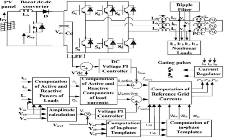
Fig.1 shows the schematic power module for implementing PI / Fuzzy logic controller for PV Interfaced Grid connected PBT based DSTATCOM for real and reactive power control required by the linear / variable loads of distribution system in MATLAB / Simulink environment using ‘Simpowersystem’ block sets. PV generation system is developed to generate a power of 20KW which is interfaced with the grid through DC-DC Boost converter and 3-Phase diode clamped voltage source converter operated by generating pulses through carrier based PWM process. Fig.2 shows the schematic diagram for extraction of reference supply currents using Power Balance Theory (PBT) based algorithm [2]. System development involves selection of various components for both reactive and real power compensation such as interfacing inductor, DC link capacitor, Ripple filter, selection of reference DC Voltage, and designing of PV generation system for desired power and DC-DC boost converter for boosting DC voltage [12].
1. Selection of DC Bus reference voltage:
The criteria for selecting DC bus voltage of VSC is that, it should be greater than twice the peak valve of phase voltage of the system and as given by Eq.(1).
2. Selection of interfacing Inductor:
The interfacing inductor of VSC is selected for minimizing the current ripples is given by Eq.(2).
3. Selection of DC link capacitor:
4. Selection of ripple filter:
High pass first-order filter is used to filter out the noise from Point of Common Coupling voltage. The basis for selecting filter components is to ensure that time constant of the filter should be very small compared with the fundamental time period. Ripple filter parameters selected are Rf=10Ω and Cf=5.5µFarads.
5. Design of the Solar Photovoltaic generation:
The SPV power generating system is designed for a 20kW peak power capacity. According to design considerations 14 modules in series, 10 modules in parallel, one solar module consists of 40 cells in series. Each cell has an open circuit voltage of 0.64 V and short circuit current of 3.7A.
6. Design of DC-DC Boost Converter:
Fig.1 shows the schematic diagram of DC-DC Boost converter. The voltage from PV cell is boosted by using DC-DC
boost converter to 700V. The design parameters of the DC-DC boost converter to boost the voltage is given as
Where D is duty cycle (D) = 1-( / ). This converter boosts the voltage of SPV array from = = 360V & =700 V. The calculated value of D is 0.485 and is output voltage from PV array. is input current ripple and for this converter design, the value of is considered 10% of input current, is switching frequency and the value of
Fig.1: Schematic diagram of grid interfaced solar PV power generating system through boost DC-DC converter and two-level VSC based DSTATCOM
Fig. 2: The Schematic diagram of Fuzzy logic controlled PBT based DSTATCOM control algorithm for extracting reference source
Instantaneous active and reactive power of the load are estimated by using Eq.(5)
Fundamental real and reactive power components of load currents are extracted using Eq.(7).
Amplitude of active and reactive power components of reference supply currents are estimated by adding output of PI/FIS controllers to the fundamental real and reactive power components of load current shown by Eq.(8).
Instantaneous valve of fundamental three phase active and reactive power components of reference supply currents are estimated by using Eq.(9).
Instantaneous fundamental reference supply currents are estimated by adding fundamental in-phase and quadrature reference supply currents as given Eq.(10).
III.FUZZYLOGICCONTROLLER
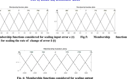
A fuzzy logic controller (FLC) consists of four stages of interfacing mechanism in operation, which are a fuzzification interface, a rule base, an inference mechanism, and a defuzzification interface. It is a common practise to use error (e) and the rate of change of error (e’) as controller inputs. In fuzzy logic based DC voltage control across DC link, the capacitor voltage deviation and its derivative are considered as the inputs of the FLC and the real power (P) requirement for voltage regulation is taken as the output of the FLC. The input and output variables are converted into linguistic variables. The following seven variables are considered, they are NL (Negative Large), NM (Negative Medium), NS (Negative Small), ZE (Zero), PS (Positive Small), PM (Positive Medium) and PL (Positive Large).
Fig.3: Schematic diagram for implementation of Fuzzy Logic Controller
The above linguistic quantification has been used in this paper to specify a set of rules or a rule-base. The rules are formulated from practical experience. For the FLC with two inputs and seven linguistic values for each input, there are 72 = 49 possible rules with all combination for the inputs [13-15]. The tabular representation of the FLC rule base (with 49 rules) for fuzzy control based DC voltage regulator is shown in Table-1.
In place of PI controller of Fig.2 proposed Fuzzy logic controller is implemented to observe the performance of DSTATCOM.
TABLE-1: 7 × 7 FLC RULE - BASE
Error/Change In error
NL NM NS ZO PS PM PL
NL ZO PS PM PL PL PL PL
NM NS ZO PS PM PL PL PL
NS NM NS ZO PS PM PL PL
ZO NL NM NS ZO PS PM PL
PS NL NL NM NS ZO PS PM
PM NL NL NL NM NS ZO PS
PL NL NL NL NL NM NS ZO
Fig. 4: Membership functions considered for scaling input error e (t) Fig.5: Membership functions considered for scaling the rate of change of error ȇ (t)
Fig. 6: Membership functions considered for scaling output
IV.RESULTS
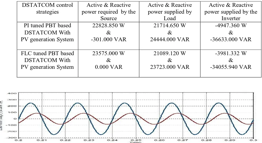
Table-2: Active and reactive power comparisions of PBT based DSTATCOM with grid connected PV generation system using PI & fuzzy logic controller for active and reactive power control
DSTATCOM control strategies
Active & Reactive power required by the
Source
Active & Reactive power supplied by
Load
Active & Reactive power supplied by the
Inverter PI tuned PBT based
DSTATCOM With PV generation System
22828.850 W & -301.000 VAR 21714.650 W & 24444.000 VAR -4947.360 W & -36633.000 VAR
FLC tuned PBT based DSTATCOM With PV generation System
23575.000 W & 0.000 VAR 21089.120 W & 23723.000 VAR -3981.332 W & -34055.940 VAR
Fig.7: The Load Phase voltage & current with PV Interfaced grid connected PBT based PI controlled DSTATCOM
Fig 9(a-b): The Real power flow in the system with PV Interfaced grid connected PBT based PI controlled DSTATCOM
Fig 10(a-b): The Reactive power flow in the system with PV Interfaced grid connected PBT based PI controlled DSTATCOM
V. SUMMARY AND CONCLUSIONS
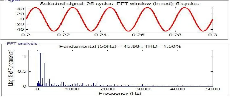
In this paper simulations pertaining to PI and Fuzzy controlled PV Interfaced Grid PBT based DSTATCOM using MATLAB / Simulink for both real and reactive power control are implemented and performance is investigated. From the above discussed results it is clear that the performance of Fuzzy controlled PBT based DSTATCOM for UPF mode of operation i.e., reactive power control over PI controlled PBT based DSTATCOM is found to be more satisfactory in respect of improvement in Total Harmonic Distortion of source current and both active & reactive power control. Solar PV generating system at distributed end supplies the required real power to the load, which relays on output voltage of VSC and also supplies losses occurring in VSC. The performance of the algorithm for dynamic loads are found to be satisfactorily with regard to system stability.
Appendix-I
Data considered for System Development and for MATLAB simulations
REFERENCES
[1] “Reactive Power Management” by D.M.Tagare, Tata McGraw Hill Publication, 2004.
[2] “Power Quality Problems and Mitigation Techniques”, by Bhim Singh, Ambrish Chandra and Kamal-al-haddad, Wiley publications, 2--- [3] “Basic Model and Governing Equation of Solar Cells used in Power and Control Applications” by Afshin Izadian, Arash Pourtaherian and
Sarasadat Motahari, IEEE Conference of Energy Conversion Congress and Exposition (ECCE), 2012.
[4] “MATLAB-Based Modeling to Study the Effects of Partial Shading on PV Array Characteristics”, IEEE Transactions On Energy Conversion, Vol. 23, No. 1, March 2008.
[5] “Photovoltaic Maximum Power Point Tracking Employing Load Parameters”, by D.Shmilovitz, IEEE Conference, ISIE 2005, June 20-23, 2005.
[6] “Mathematical Modeling of Photovoltaic Module with Simulink”, by N. Pandiarajan and Ranganath Muthu, International Conference on Electrical Energy Systems (ICEES 2011), January 3-5, 2011.
[7] “MATLAB / Simulink PV Module Model of P&O And DC Link CDC MPPT Algorithms with Lab view Real Time Monitoring And Control Over P&O Technique” by Williams K. Francis, Shanifa Beevi S and Johnson Mathew, International Journal of Advanced Research in Electrical, Electronics and Instrumentation Engineering, Vol. 3, Special Issue 5, December 2014.
[8] “Power Quality Improvement by using DSTATCOM”, by P. Bapaiah, International Journal of Emerging Trends in Electrical and Electronics (IJETEE), Vol. 2, Issue. 4, April 2013.
[9] “A Comparison of Control Algorithms for DSTATCOM”, by Bhim Singh and Jitendra Solanki, IEEE Transactions on Industrial Electronics, Vol. 56, No. 7, July 2009.
[10] “Dstatcom control algorithms: A review”, by Ambarnath Banerji, SujitK Biswas and Bhim Singh, International Journal of Power Electronics and Drive Systems, Vol.2, No.3, Sep.2012.
[11] “Modified Power Balance Theory for Control of DSTATCOM”, by Bhim Singh and Sunil Kumar, Power India Joint International Conference on Power Electronics, Drives and Energy Systems (PEDES), 20-23 December, 2010.
Grid voltage & grid frequency 230V+ and 50Hz respectively PV Open circuit voltage ( ) 0.64 V
PV Short circuit current ( ) 3.4 A One module of PV in series 40 Nos Total Number of modules in series & Parallel 14 &10 Nos
Source Impendence Rs=2Ω, Ls = 1mH
Interfacing Inductor 5mH
Ripple Filter 5Ω, 10mH
DC-Link capacitor 700µF
Duty Cycle of Boost converter 0.4857 FLC Scaling Factors for the DC Voltage
Regulator
GE =0.00319; GCE =1.7778; GCU =0.53559
1.5 &2.4
December 2016..
[14] “Performance Enhancement of PBT Based DSTATCOM Using Fuzzy Logic Controller”, by K. Goutham Kumar, T. Praveen Kumar and Dr. K. Sumanth, International Journal of Research in Engineering & Advanced Technology (IJREAT), Volume 4, Issue3, June - July, 2016. [15] “Simulation of SRF Based DSTATCOM With Grid Connected PV Generation System Using Fuzzy Logic Controller For Reactive Power
Management”, by R. Deepak Singh, T. Praveen Kumar and Dr. K. Sumanth, International Journal of Advanced Research in Electrical, Electronics and Instrumentation Engineering, Vol. 5, Issue 7, July 2016.
[16] “Fuzzy Gain Scheduling of PID Controllers”, IEEE Transaction on System man, andCybernetics, Vol.23. No. 5, September/October 1993. [17] “Enhancement of Power Quality with ANFIS Controlled DSTATCOM in Four Wire Three Phase Distribution System” by R.V.Murali,
K.Srinivasu and L.V.NarasimhaRao, Biennial International Conference on Power & Energy System towards Sustainable Energy (PESTSE), 2016.