and requires a sub-routine to be stored only once in any part of the memory.
New Instructions
But for several minor exceptions, Univac II exe-cutes all Univac I instructions in exactly the same manner as Univac I. Certain of these instructions, however, have been assigned new functions which serve to extend their overall flexibility. The V instruc-tion, for example, will now transfer from one to nine words ins·tead of merely two as was formerly the case, and the Y-Z instructions will now transfer groups of words ranging from ten to sixty in number in steps of ten words. Formerly, ten words and only ten words could be transferred when using this instruction. As a further example of the greater flexibility permitted in Univac II, the extract function (or E instruction), formerly limited to register A, has been generalized so that it now covers all instructions which read out of the memory (A, B, D, L, M, N, P and S). The EF instruction permits recombination of selected characters from register A with the remaining charac-ters of the word in memory location. Instruction A has been extended in usefulness also, and in addition, an I instruction (transfer from register L to memory) has been adopted as a standard command.
Overflow
With Univac I I the addition of a 1 to the control counter reading following overflow is automatic. When using Univac I programs on Univac II a special
switch will inhibit the addition of 1 to the control counter reading following overflow and cause the 3rd instruction digit to be interpreted in the memory switch as a decimal zero regardless of its actual value. Therefore, in Univac I programs where the 2nd and 3rd instruction digits have been used for overflow control, the presence of these digits will not influence the execution of the instruction.
Compatability Switch
A switch provides three circuit corrections to promote compatibility of Univac I and II programs. Any other incompatibility will require program cor-rections. With the switch in position to handle Univac I programs, the Univac II will treat the 3rd instruc·tion digit as zero, for V, W, Z and Y instruc-tions, treat the 2nd instruction digit as zero and restore the Univac I mode of overflow action on the control counter.
Tape Handling Operations
As many as 16 Uniservos may be connected to Univac by a metallic duct carrying the necessary cables. Univac can read from ta~s mounted on these Uniservos with the tapes moving forward or backward. Univac can record on a tape moving forward. It can read from one Uniservo, write on a second and rewind all other Uniservos simultaneously. Unless there is another read, write or rewind instruction immediately following, Univac may continue to compute while the reading, writing and rewinding operations are being performed.
Tape recording for Univac II must be done according to the following:
Spacing per block
(with 1 in between blocks) Pulse denSity per inch Blocks per reel Read time per block Per reel
Rewind time per reel Feet utilized
UNIVAC II
4.60 in
(3.60 in per block) 200 nominal
4,000 (metallic) nominal 51 msec. minimum (metallic and mylar) 3.4 minutes minimum (metallic)
3.1 minutes (metallic) 1,535 ft (metallic) 2,400 ft (mylar)
1000
PROGRAMMING SPECIFICATION:3
Library and compiler routines for lnathematical and cOlllmercial use, and service routines for maintenance uses, are available to the customer.
Modified or Added Instructions
I instruction providing for transfer of information from register rL to memory.
Field selection as specified by a second instruc-tion d.igit F. For the instrucinstruc-tions A, B, D, L, M,
N, P and S it operates so that the wor~ transferred from memory location M contains only those digits from the columns of "m" which corres:pond to the col-umns in register F containing "odd" characters. The remaining column poSitions of the word, transferred from "m" to the receiving register contain decimal zeros.
The EFm instruction permits insertion into a word in memory location "m" of the characters in those columns of register A Which correspond to the columns contai.ning "odd" characters in regis·ter F. "Odd" characters in the Univac code have a binary zero in the least Significant binary position. rA will also contain the complete word which is restored at memory location "m".
Add to memory. The add to memory instruction is effected by adding a special designator (li) in the 2nd di.git position of the A instruction. It results in the execution of an A instruction followed by an automatic H instruction. Register rA will retain the total (rX + rA) at the conclusion of the add to memory instruction. An equivalent subtractive opera-tion i.s performed by the SH instrucopera-tion.
Multiple Word Transfer
The Vnlml, Wn2m2 word transfer instructions trans-fer one to nine words as specified by- the numeric (n) appearing in the second digit position. Register rW provides the transfer storage. The transfer is made using V and W instructions as for Univac I ex-cept that no reversal of position occurs in a 2 word transfer as may in Univac I. Note also that if the second digits of the V and W instructions are not equal special transfers result. If ~ > n
2• The first (~ - n2) words transferred from ~ to rW are not transferred from rW to m
2• If nl < n2• The (n - n ) words transferred to rW by a previous V
in~truciion are transferred to m
2 followed by the~
words of the current V instruction. When n=
°
the instruction will be processed as a skip instruction.The Ynlm." Zn2nJ." pair of instructiQns permits the transfer of groups of 10, 20, 30, 40, 50, or 60 words as designated by a numeric
(1
through 6) in the sec-ond digit position of the instruction. The Y, Z instructions use rZ as transfer storage. If the second digits of the Y and Z instructions are not equal, special transfers result. If ~ > n2• The first nl - n
2) tens of words transferred from ~ to rZ will not be transferred to ~. If ~ < n
2• The (n2 - nl) tens of words transferred to rZ by a pre-vious Y instruction are transferred to m2, followed by the nl tens of words of the current Y instruction. When n = 0, 71
8,
or9,
the instruction will be pro-cessed as a skip instruction.Tape Writing DenSity Controls
calling for a 124 pulse per inch writing density. These manual pushbuttons will be in addition to those available for block subdivision and delta (~) second digit decoding of in/out instructions.
1nm instruction causes writing at 50 pulses per inch. Block subdivision controls will operate as in Univac I with all densities. Block divisions (space between blocks) will be 1 inch except for the 124 ppi denSity. This will be 2.4 inches.
Memory Clear
A pro~ected ~itch will provide for memory clear (rM) to decimal zero. Register rM will clear on read-in.
Buffer Register Clear
Registers rO, rI, rZ and rW clear only on read-in. Instruction Execution Time
Basic machine cycle is reduced from four to three cycles (a cycle is omitted).
All instructions are performed at minimum latency rates.
USN l!50
Outstanding features include self-checking of the computer through use of duplicate circuitry in both the arithmetic and logical units.
Standard tape labelling techniques are used; stor-age, shipping, protection from humidity, temperature and physical handling problems are minimal. System operates with metallic magnetic tape. Back-up master tape files are stored in a remote location as pro-tection against loss,of information through electri-cal, fire or other damage to the tapes stored in computer center library.
This activity has experienced a high performance rate in the use of metallic magnetic tape with its ADP system. A number of tests have been made with various types of mylar base tape; but, to date, the performance of mylar tape on Univac II is unsatis-factory.
Metropolitan Life
Outstanding features are that the system is complete-ly self checking and simple to operate. Each tape is kept in a cardboard .box, labeled on the reel and on the edge of the bOX, stored like books on open shelving with stall dividers every three reels, in locked fenced-in area. No special humidity, fire, or dust protection needed for metal tapes.
Pacific Mutual
Outstanding features include self checking and duplicated circuitry affording basically error free output. The Unitypers allow a complete tape system, completely devoid of any type of punch card.
I f anything, we have erred in over controlling for everything except humjdity, which we do not control.
We feel that for our job we have the best equip-ment presently available and are trying to keep aware of the next generation.
USS
Metal cases are used for ordinary filing. Fireproof cabinets for some master tapes.
PRODUCTION RECORD
Number of systems delivered 32FUTURE PLANS
USN ESONo new components or modifications to the installed ADP system are contemplated by this activity.
It is planned to retire the present ADP system and replace it with a more powerful, solid-state ADP system during FY 1962.
Several new applications will be pr.ogrammed for processing, in addition to the applications already in production on the present ADPs, at such time as the replacement system is installed.
Metropolitan Life
Plan to get from two to four more systems of the 3rd generation type such as HOneywell 800, IBM
ToBO,
etc.Plan to extend tape files from present
6
million policies, to include other types for about 40 million policies, and expect to run these files daily instead of bi-weekly, and extend the area of operations per-formed.Plan to be installing in many areas of work pre-yiously deferred because of lower expected savings and/or greater planning effort.
Pacific Mutual
We have gone from Univac I to Univac II and antici-pate moving to Univac 1111 - IBM 701 - Datamatic 801-RCA 501 or some other system as soon as the new gen-eration of computer renders ours so obsolete as to be impractical to retain. This could conceivably be in 1963, 64 or 65.
We are continually investigating, modi~ing, etc., our system and equipment and looking to add new applications.
USS
Additional applications of the same type as current-ly processed will be installed.
New systems being reviewed and evaluated for con-sideration.
I NSTALLAT IONS
u.
S. Navy Electronics Supply Office Great Lakes, IllinoisU. S. Department of Agriculture Commodity Stabilization Service Kansas City, Missouri
Metropolitan Life Insurance Company (3)
1 Madison Avenue New York 10, New York
Metropolitan Life Insurance Company (1) 315 Park Avenue So.
New York City, New York
Pacific Mutual Life Insurance Company Pacific Mutual Building
Los Angeles, California
United States Steel Corporation 1509 Muriel Street
UNIVAC
m
MANUFACTURER
Univac III Data Processing System Remington Rand UnivacDivision of Sperry Rand Corporation
Photo by Remington Rand Univac, Division of S:t:erry Rand Cor:~oration
APPLICATIONS
System is designed for commercial data processing as well as scientific applications. The UNIVAC III is a medium-cost, high performance ele~tronic data processing system designed to meet the broadest possible needs of business and science. The magnetic core memory holds from 8,192 to 32,768 words in in-crements of 8,192 words each with a cycle time of
4.5
microseconds. Words can be pure binary, binary coded deCimal, UNIVAC XS-3, or any other form. UNI-SERVO III tape units allow reading, writing, and computing simultaneously. The reAd-write rate is 200,000 digits per second.Up to thirty-two Uniservo III tape units and six qniservo II tape units are possible. Auxiliary on-line units may include card-readers which operate at a rate of 700 cards per minute, high-speed print-ers at 700 lines per minute, card punch units at 300 cards per minute, mass storage and other devices. The UNIVAC III is compatible with other UNIVAC tape
UNIVAC III 1002
units or with those of other manufacturer.
PROGRAMMING AND NUMERICAL SYSTEM
Internal number systemBinary digits/word Decimal digits/word Alphanumeric char/word Instructions per word Instructions decoded Arithmetic system Instruction type
Binary or binary coded dec 24
6 4
1
75 (approx) Fixed point one-plus-one Number range
Instruction word format
Parity Indirect Address IR Oper AR/IR I m
27 26
Automatic built-in subroutines includes automatic interrupt.
Automatic coding includes COBOL and assembly system. Registers includes four accumulator registers, fif-teen index registers, and thirfif-teen memory address counters.
All instructions are automatically modified by the Index Register designated. System is able to select as an operand from one bit to ninety-six bits through use of a field select control word. From one to four-word operands are possible.
All users of UNIVAC III will be provided with a comprehensive programming package. The initial pack will contain COBOL, SALT Assy (Symbolic Assembly I,an-guage Translator), sort and merge generators, and an executive routine including contingency and error check routines.
ARITHMETIC UNIT
Incl Stor Access Exclud Stor AccessMicrosec
Add 8
Mult 48-124
Div 68-144
Arithmetic mode
Microsec 8 48-124 68-144 Serial by digit Parallel by bit Timing (Computer) Synchronous Operation (System) Concurrent
6+6 Digits 6x6 Digits 6/6 Digits
The computer instruction execution cycle that the effective access time is zero.
is such
Media Core
Drum (Mass Memory) Magnetic Tape
STORAGE
No. of Decimal Access Words Digits Microsec 32,768 196,608 1.07 4,000,000/Drum 24,000,000 385 No. of units that can be connected 32 Units No. of chars/linear inch 1,333 Char/inch Channels or tracks on the tape 9 Tracks/tape Blank tape separating 0.68-0.78 Inches
Tape speed 100 Inches/sec
Transfer rate 133,300 Chars/sec
Start time 6.3 Millisec
Stop time 6.3 Millisec
Average time for experienced
operator to change reel of tape 30 Seconds Physical properties of tape
Width 0.5 Inches
Length of reel 2, 400 Feet
Composition Mylar
In addition to the units described above, a maximum of 6 Uniservo II may be included in the system. Check during writing on Uniservo III. Digital repre-sentation (4 bits) 200,000 pulses/sec transfer rate, 2,000 digits/inch.
INPUT
Media Bpeed
Cards 700 cards/min 80 or 90 column. No plugboard
Uniservo III 200 pulses/sec (Digital) Up to 32 in system
L33.3 (Alphanumeric) Parallel read-write
Uniservo II 25 pulses/sec (Alphanumeric) For compatibility with other Univac Tape Systems Paper Tape
OUTPUT
Media Speed
Cards 300 cards/min 80 or 90 column. No plugboard Card Printing Print - 900 lines/min
Punch Punch - 150 cards/min Punches and prints same card in one pass. High Speed Printer 700 lines/min
Editing program controlled. Paper Punch
CHECKI NG FEATURES
Modulus 3 word parity checking, arithmetic, trans-fer and comparison operations, and logical checks.
POWER, SPACE, WEIGHT, AND
SITE PREPARATION
Power, computer Volume, computer Area, computer Room size Floor lea ding Weight, computer
75.2 Kw 94 KVA 900 cu ft 1,500 sq ft
0.80 pf
43 ft x 43 ft x 12 ft 200 lbs/sq ft
1,100 lbs concen max 27,225 lbs
Heat exhaust vents should be located at roof of each unit. Air conditioning output ducts should be near unit inlet vents. Total input line current 261 amperes/line. Recommended main circuit break-er 400 ampbreak-eres/line. 115 volt convenience outlets should be located every 6-8 ft approximately 2 1/2 ft off floor.
These figures include the Univac III large system w/16 tape.
PRODUCTION RECORD
Number on order 25
COST, PRICE AND RENTAL RATES
Basic System UnitsComputer - 8 K Memory High Speed Reader Punch Unit
High Speed Printer Uniservo III
Synchron-izer-Max. 16 Uniservos
Price $390,000
35,000 40,000 79,000 145,000 Uniservo III Power Supply 17,500
Uniservo III 24,000 ea.
Additional EqUipment Units Card Punching Printer $ 197,500
Uniservo II 20,000
Uniservo II Synchronizer 92,500 Uniservo II Power Supply 17,500 Memory-Add. 8 K - 67,500
Add. 24 K 193,500
'·''1.d Uniservo III 145,000 lchronizer or Mass
mory Device
Monthly Rental $ 8,000
750 850 1,650 2,900 350 500 ea. :Ii 4,300
450 1,925 350 1,400 4,030 2,900
Maintenance/service contracting is included in rental :price.
PERSONNEL REQU I REMENTS
'rraining made available by the manufacturer to the 11ser includes a program-systems course for experi-enced programmers of 5 weeks duration and for in-experienced programmers of 8 weeks duration.
RELIABILITY, OPERATING EXPERIENCE,
AND TIME AVAILABILITY
The system is completely self-checking.
ADDITIONAL FEATURES AND REMARKS
Cmtstanding features are modularity, field selec-tion, multiple word operand, index registers, scatter-read-gather write, and indirect addressing.Unique system advantages includes automatic inter-rupt, combined with above features.
The normal procedures for handling Mylar tape may be used.
A one addressable modulus 24 hour clock is included. It keeps time in tenths of a second and has a digital output which can be read ~y the computer program. As faster components become available and more power-1\li input-output units are developed, they will be
incorporated in this system without requiring program changes.
Typical Basic. System
Diagram by Sperry Rand Corporation, Remington Rand Univac Division
Typical Expanded System
Tape Line Configurations
UNIVERSAL DATA TRANS
MANUFACTU RER
Universal Data Transcriber Naval Weapons Laboratory
Dahlgren, Virginia
Photo by U. S. Naval Weapons Laboratory, Dahlgren, Va.
APPLICATIONS
Located at the Naval Proving Ground, the system is used for conversion of scientific or management data from one medium or format to another, primarily in the processing of input and output for the NORC or other computers.
PROGRAMMI NG AND NUMERICAL SYSTEM
Internal number systemBinary digits/word Binary digits/character Instruction word format
MO Ml
8 1 8 6
Operation B-Register Code
Specifica-tion
Binary
36
8 + 1 check bit
I
M2 M35 118 1 8 1
Address Specifi- Limit cation of Refer- Value ence to Memory of Bx Since there are no multiply or divide orders, the operating binary point may be considered to be in any
UNIVERSAL DATA TRANSCRIBER
1006
convenient location. The carry (borrow) bit may be propagated from character to character in addition
(subtraction) with use of double precision orders. A single reference to the memory brings out four characters designated as MO, Ml, M2, and M3 into the memory register. Addresses evenly divisible by four always correspond to the character read out as MO. Instruction words consist of the four eharacters MO, Ml, M2, and M3. Instruction words are logically di-vided into
4
fields as shown above, nrunely: Operation Code, B-Register specification, Address Specification of reference to memory and the Limit Value of Bx.The operation of the system depends llpon the micro-programming of the computer to generate special orders which will transfer data from the particular external input device currently in use to the computer memory and from the memory to the external output device currently in use. The use of micro-programming, which is accomplished by use of a plugl)oard, allows an efficient transfer of data between the computer memory and the external devices with a minimum of
the use of an appropriate stored program. This gives a very flexible system since all that is required to change the system from one job to another is to change the connections to the external equipment, insert a different plugboard, and load a new program into the computer memory. This system was conceived, designed and is under construction by the Computer Research and Development Branch of the Computation and Exterior Ballistics Laboratory of the U. S. Naval Proving Ground, Dahlgren, Virginia.
The system registers are: 1 Input register
1 Output register 2 Computing registers
6 B-registers (address modifiers) 1 Instruction register
1 Instruction counter
Indicator latches (single bit registers) Other special registers
External devices communicate with the computer via the input and output registers under control of the computer. The input register can select at high speed from either of two different external devices. The output register is normally connected to only one unit. Indicator latches are used both to control the external devices and to signal the condition of the external devices to the computer. Special electronic signal generating equipment tailored to each type of external device is used to facilitate communication with the input register, output register, indicator latches and the external device.
ARITHMETIC UNIT
Operation time, incl 1 memory access 11 microsec Operation time, incl 2 memory accesses 21 micro sec
Two memory accesses are required for such orders as read out and store orders.
Medium :Magnetic Core
STORAGE
No. of Words 2,048No. of Digits 36 bits/word
INPUT OUTPUT
Media Speed
Access Microsec
10
Magnetic Tape (NORC) 70,000 dec dig/sec Magnetic Tape (Potter 906) 37.5/75 in/sec
200 char /inCh Paper Tape (Digitronics) 300/600 Char/sec (read) Paper Tape (Teletype) 60 Char/sec (read) Paper Tape (F1exowriter) 10 Char/sec (read) Paper Tape (Teletype) 60 char/sec (punch) Paper Tape (Flexowriter) 10 Char/sec (punch) Magnetic Tape (Analogue, Ampex Model FR-100A)
Speeds are 1.875, 3.75, 7.5, 15, 30 and 60 in/sec. Cards (Remington Rand) 450 cardS/min (read) Cards (Remington Rand) 100 cards/~in (punch) Cards (IBM Model 101) 450 cards/min (read) Cards (IBM Model 514) 100 cards/min (punch) Typewriter (Flexowri ter ) Keyboard (entry) Typewriter (Flexowriter) 10 Char/sec (print)
CHECKI NG FEATURES
The computer has automatic circuitry built into the system to check the accuracy of its operation. This check adds a parity bit to the 8 bits in each character so that the modulo two sum of the binary oners of these 9 bits is always odd. This check bit is generated after data enters the input register, is corrected as the characters are modified by various orders, and is stored in the memory along with the character. An automatic check is made for the pres-ence of the proper parity count as the data is trans-ferred from the memory into the working registers or the instruction register. The values in the B registers are checked automatically as they are used and there are checks on the execution of the overlay and shifting operations in the computing registers.
Whenever possible checks will be made on the accur-acy of data transmission between the computer and the external devices. For example, in card reading, data will be loaded into two independent shift registers from two reading stations, and after the card images are assembled in memory they will be checked against each other. In punching data into cards, the card will be read back into the computer after being punched and this card image will be checked against the card image sent out to the punch. When magnetic tapes are written the data will be read back into the computer and a check will be made on the correct-ness of the data.
POWER, SPACE, WEIGHT, AND SITE PREPARATION
Power, computer 5 KwRoom size, computer No special preparation. part of a large system.
6 KVA 0.83 pf 480 sq n
Air conditioned as a small
PRODUCTION RECORD
Number producedNumber in operation
1 1
COST, PRICE AND RENTAL RATES
Total approximate cost $350,000 for all units listed except IBM 101 and 514, which are rented.Programmers Operators Engineers Technicians
PERSONNEL REQU I REMENTS
Three 8-Hour Shifts 3
RELIABILITY, OPERATING EXPERIENCE,
AND TIME AVAILABILITY
Time is available for rent to qualified outside or-ganizations. System has been in use on several
pro-jects since January 1960. Some engineering work continues. It may be used by government agencies or contractors when time is available.
ADDITIONAL FEATURES AND REMARKS
The most outstanding difference between the com-puter of the Universal Data Transcriber and any other single address binary computer is the availability of the plugboard and the plugboard instructions. The plugboard is divided into three regions. The first region consists of information coming from equipment in the computer to the plugboard. This includes al.l of the registers, such as Register 1,Register 2, Input Register, Output Register, Instruc-tion Register, InstrucInstruc-tion Counter,
B7,
and the in-dicator latches, plugboard instruction specification and the internal clock. Also in this region are external inputs from the various input and output devices which have been converted to the proper sig-nal levels. The second region of the plugboard con-sists of a set of approximately 75 logical packages. These packages are identical to those used in the construction of the rest of the computer. In the third region of the plugboard are exists from the plugboard of the control lines in the computer. These lines control the transfer of data from "reg-ister to reg"reg-ister", use of the B Registers, control-ling memory cycles, setting of indicator latches, shifting various registers, etc. Thus by using all three regions of the plugboard almost any conceivable (or desirable) cycle of actions can be controlled from the plugboard. This feature is primarily for use with external devices to get data to or from them and the memory of the DDT.The indicator latches in the computer are used primarily for communication between the DDT and ex-ternal devices. For example, some of the indicator latches could be wired, via the plugboard, to con-trol the stopping, starting, or reading or writing of a tape unit. Other indicator latches could be used to ind.icate to the DDT that an external device is in certain conditions, for example, that a card reader is moving cards, or ready to scan one row of information, or that it is out of cards, etc. Thus the program can control external devices, and exter-nal devices can be sensed by the program by use of the indicator latches.
Another feature of the DDT is the "Program Inter-rupt" ability. If a particular exit on the plug-board is energized the computer will go into a pro-gram interrupt cycle. This exit can be energized from an indicator latch, or combinations of indica-tor latches and various conditions by wiring on the plugboard. When this condition occurs the computer will automatically make a program transfer to in-struction location
4
at the end of the current in-struction. The address (Y) of the instruction which would have normally been executed next, if the pro-gram interrupt condition had not occurred, will be automatically stored in character locations 1 and 2in a form so that if the character in location 0 is the code for a program transfer (jump) command and the instruction at location 0 were to be executed, the computer would jump to the proper address
(Y).
When this feature is used the program, starting at location4,
must be suitable to take the appropriateUNIVERSAL DATA TRANSCRIBER 1008
action for the condition which caused the jump. After this is done, the program would normally remake the appropriate registers, and then jump to location 0, which would cause the jump back to the main program at the proper place. By using this feature the com-puter can react rapidly to external control informa-tion without requiring repeated sensing on the condi-tion.
The major advantage of the Universal Data Transcrib-er is its flexibility. It is not tailored to any
specific computer or type of data conversion and is therefore not likely to become obsolete as fast as many specialized converters. The micro-progrrumning and stored program features makes it easy to imple-ment almost any desired conversion with a minimum of engineering effort and special equipment. The major disadvantage to this approach is that it is more ex-pensive than any single specialized converter.
To establish the capabilities of the Universal Data Transcriber several preliminary programs have been prepared. One program for converting 80 column alphanumeric IBM cards to NORC magneti(~ tape provides for arbitrary code and format conversion, specified by header cards, and converts data to magnetic tape at a rate of 450 cards per minute. Similar programs have been developed for conversion from one magnetic tape system to another. If there is a conversion in both the code representation of the data and ill the format, but not in the number base, the system can convert
4, 5, 6, 7,
or8
bit characterB from one form to another at a rate of approximately 3,000 crulracters per second. Conversion can be made from 48 bit binary words to decimal digit words at a rate of approximate-ly 16 words per second. Conversion can be made from 13 digit decimal words to binary words at rates in excess of 50 words per second.The Universal Data Transcriber is being designed and constructed at the U. S. Naval Proving GrOlmd, Dahlgren, Virginia. Subcontractors are providing the memory, logical building blocks, and various specialized input and output circuitry.
to or from the Naval Ordnance Research Calculator.
INSTALLATIONS
Computation and Analysis Laboratory Naval Weapons LaboratoryVERDAN
Autonetics VERDAN MBL-D9A Computer
APPLICATIONS
The computer is used in real time control systems, such as inertial navigation, bombing, weapon system central digital computer, flight control, ground checkout and alinement, and process control.
As a data system, it is used for scientific computa-tion, impact predicicomputa-tion, and mission readiness.
The VERDAN computer consists of three interconnected computational centers: (1) an incremental or DA sec-tion (2) a whole valve or GP section and (3) an input-output section. All three centers may be opera-ted simultaneously. The GP section directs all com-putation.
PROGRAMMING AND NUMERICAL SYSTEM
Internal number systemBinary digits/word
Binary 24 Binary digitS/instruction 22
Instructions/word 1
Instructions decoded 52
Arithmetic system Fixed point
Instruction type One and 1/2 address format Number range As an integer: _(22 3 ~ W < (223_1 )
As a fraction: - 1 < W < 1 _ 2-23 Instruction word format
0 1 2 8 9 12 13 161 17 23
Not Used Sector of Next Operation Channell Sector Instruction Code Operand Addre s s
ARITHMETIC UNIT
Incl Stor Access Exclud Stor Access Add
Mult Div
Microsec 160
Construction (Arithmetic unit only)
Transistors 1,500
Diodes 10,670
Resistors 4,500
Arithmetic mode Serial
Timing Synchronous
Operation Sequential
Microsec 80 2,000 2,000
The clock rate is 332.8 kilocycles/sec. information is for the G.P. only.
Above
STORAGE
Medium No. of Words
Rotating Disc Memory 1,664 The average access time is one half olution, or 5 milliseconds.
Magnetic tape is under development.
No. of Bin Digits/Word
24 of a disc
rev-MANUfACTURER
AutoneticsDivision of North American Aviation
INPUT
Media Speed
16 DC Voltages
(± 0.5% Range tlOV)
100 times/sec 3 Ternary Coded Pulse
(using 8 integrators) 32 Shaft Encoder
800 times/sec 100 times/sec 800 times/sec (20 significant bits)
3 Resolver Incremental (using 8 integrators) Tape Reader
Manual Control
OUTPUT
Media Speed
15 DC Voltages 100 times/sec (to.5% Range tlOV) Serial Digital 332.8 bits/sec
16 Shaft Encoder 100 times/sec (20 significant bits) 4 Bin Code 100 times/sec
4 Ternary Code 100 times/sec Nixie Display on control panel Paper Tape Punch 5 channel Typewriter
C
I RCU tT ELEMENTS OfENTI RE SYSTEM
Type Diodes Transistors Capacitors Resistors Quantity 10,000 1,500 670 4,500CHECKI NG fEATURES
Parity on input··output. The same problem can be run
on GP and DDA internally and answers compared.
POWER, SPACE, WEIGHT, AND SITE PREPARATION
Power, computer 0.320 Kw 0.8 pf 400 eycle, 3 phase Volume, computer 1.4 cu ftWeight, computer 82 Ibs
Air conditioner is not normally required if :lnput air is between OOF and 900F. Blower must be supplied
by user.
PRODUCTION RECORD
Number produced to date 180 Number in current operation 180Number on order 883 (approx.) Anticipated production rates 5/week Time required for delivery 10 months
COST, PRICE AND RENTAL RATES
Basic system consists of the computer - VERDAN, man-ual control panel, and paper tape reader. Additional equipment includes paper tape punch, tape prep. equ.ip-ment, test equipment - C297A, and typewriter. Prices are available upon formal request to Autonetics.PERSONNEL REQU I REMENTS
This computer was primarily designed for unmanned control systems and thus can operate for long periods of time unattended.
Training made available by the manufacturer to the user includes programming course and operation and maintenance course.
RELIABILITY, OPERATING EXPERIENCE,
AND TIME AVAILABILITY
Calculated mean time before failure, from parts count, is 160 hours. Realized MTBF under steady state opera-tion is 250 hours.
ADDITIONAL FEATURES AND REMARKS
Outstanding features include multiple input-output, combination GP/DDA, and small size.Due to the manner in which, the inputs and outputs are handled - internally - the computer does not halt while inputing or outputing, thus the GP, DDA and
input-output operations can proceed simultaneously, making this machine almost ideally suited to the real-time control problem.
The VERDAN contains a non-volatile magnetic memory. Provisions are incorporated such that in case of power failure, all intermediate information is stored on a memory channel. Upon resumption of power, the flip flops and registers etc., are reset and the pro-gram computation resumes at the point of interruption.
FUTURE PLANS
A digital, addressable magnetic tape reader and writer is under development as an accessory for this machine, in order to extend its capabilities.
INSTALLATIONS
AutoneticsDivision of North American Aviation 9150 E. Imperial Highway
Downey, California
WESTINGHOUSE
AIRBORNE
Westinghouse Airborne Digital Data Processor
Operand Memory
APPLICATIONS
System is used to process radar data, generate synthetic displays, and direct aILtenna. The computer is used also to conduct built in system tests, per-form diagnostic tests of the Data Processor itself and generate calibration displays.
The Westinghouse Airborne Digital Data Processor is a problem oriented general purpose digital compu-ter developed by Westinghouse for the Bureau of Aeronautics. Problem orientation of the Data Pro-cessor stems from its function as a sub-system of a radar processing system with multiple target hand-ling capability.
WESTINGHOUSE AIRBORNE 1012
MANUf ACTU RER
Air Arm DivisionWestinghouse Electric Corporation
Photo by Westinghouse Electric Corporation
PROGRAMMING AND NUMERICAL SYSTEM
Internal number systemBinary digits/word Binary digitS/instruction Instructions/word
Binary 24
21
One (two instructi.on words per memory line) 4096
Fixed point One address Instructions decoded
Aritbmetic system Instruction type
Number range - l < n < +1
Power Supply
Registers and B-boxes Accumulator Q-Register M-Register
X-Register 3 Index Registers IS-Register
Stored Data Processing program consists of many sub-routines.
Data-constant words are expressed in a complement form. Operand words are stored two words per operand memory line. Programmer has choice of left or right word, left or right half of left word, or left or right half of right word. These choices provide for maximum use of data locations.
AR ITHMETI C UNIT
Incl. Star. Access Exclud. Star. Access
Add
Mult
Div
Construction
Microsec
3
20 40
(Arithmetic unit only) Transistors 2,600 Arithmetic mode Parallel Timing
Operation
Synchronous Sequential
Microsec 1.4
20 40
Photo by Westinghouse Electric Corporation
STORAGE
Media No. of Words Magnetic Core 4096 Inst Words Magnetic Core 1024 Oper Words Magnetic Tape
No. of Dig/Words
21 24
Access Miqrosec
0.2
0.8
No. of units that can be connected No. of characters/linear inch Channels or tracks on the tape Tape speed
1 Unit 200 CharS/inch
7 Tracks/tape 75 Inches/sec
3 Mil11sec Start time
Stop time 3 MilUsec
Physical properties of tape
Width 0.5 Inches
Length of reel 2,400 Feet
Composition Mylar
Selected data recorded on tape compatible with IBM 727 tape unit.
Input Unit
INPUT
Speed MediaHi-speed Block
Transfer 3 micro sec/data word Voltage to Digital
75
micro secSense Inputs 3 micro sec
0.1% Resolution Special input unit designed to receive information from radar and present it to Data Processing units.
OUTPUT
MediaHi-speed Block Transfer Digital to D-C Voltages
0.1% Resolution Digital to A-C Voltages
0.2% Resolution
Speed
3 micro sec/data word
15
micro sec read-out 9 micro sec read-out Special output unit designed to receive data from the arithmetic/control unit, decode data, output to the antenna director, display of tracked targets on console, and output to tape unit.WESTINGHOUSE AIRBORNE
1014
Photo by Westinghouse Electric Corporation
CIRCUIT ELEMENTS OF ENTIRE SYSTEM
Type Quantity
Diodes
15,985
Transistors
7,597
Magnetic Cores 113,600
Gating systems operate on DC levels 'with approxi-mately 10 mil1imicroseconds of delay per stage.
Multi-aperture core Instruction Memo:ry with :Non-Destructive Read-out.
CHECKI NG FEATURES
Internally Programmed Self TestArithmetic/control monitor capable of testing and holding the contents of a particular register at any
prescribed time.
Arithmetic/Control Unit
POWER, SPACE, WEIGHT, AND SITE. PREPARATION
Power, computer and power 1.8 Kw 1.8 KVA 1.0 pf Volume, computer 6.5 cu ftArea, computer Dependent on mounting application Weight, computer 250 lbs
Data Processor is designed for airborne use. Mounting structure depends on space available. Cool-ing required is a blower with a capacity of 200 cfm at max amb temperature 38°C min air denSity .052 lbS/ft2 . System requires 115v, 400 cycle, 3-phase, 600 watts/phase, or 28v D.C. 3 wire.
PRODUCTION RECORD
Number produced to date 2 Number in current operation 2Current operating models are prototype.
RELIABILITY. OPERATING EXPERIENCE,
AND TIME AVAILABILITY
System features and construction techniques utilized by the manufacturer to insure required reliability include selected standard parts proven long life items with extensive life testing operations, elec-trical components derated to operate at 20% of nomi-nal voltages and power ratings, and circuits designed
Photo by Westinghouse Electric Corporation
to accomodate wide swings in component parameters.
ADDITIONAL FEATURES AND REMARKS
Outstanding features include Hi speed (300,000 operations/sec) in a ruggedized, small package, high reliability, and general purpose command repertoire with three Index Registers.Unique system advantages include Non-Destructive Instruction Store with 1 microsecond memory cycle time, and split word storage, allowing programmer a choice of a 24 bit whole word or a 12 bit half word.
INSTALLATIONS
Westinghouse Electric Corporation Air Arm DivisionAvionics Systems Section (454) Box 746
WH I RL WIN 0
II
The Whirlwind Computer
APPLICATIONS
ManufacturerScientific and engineering computation. The research reported in this computing system description was sponsored by the Office of Naval Research.
Air defense experiments leading to development of the SAGE System.
The Whirlwind I Computer was declared excess to the needs of the M.I.T. Lincoln Laboratory in the spring
of 1959. Subsequently, the computer was leased by the Office of Naval Research to the Wolf Research and Development Corporation, Boston, Mass. The Wolf Research and Development Corporation then undertook the disconnecting and moving of the computer from the
M.I.T. Barta Building. This move which commenced
about 1 January 1960 was successfully completed by 1 May 1960. The computer is presently stored in a Navy warehouse and it is planned to move the machine and make it operational at a new site during early 1961.
WHIRLWIND' II
MANUFACTURER
Massa.chusetts Institute of Technology Digital Computer LaboratoryPhoto by Massachusetts Institute of Technology
PROGRAMMING AND NUMERICAL SYSTEM
Internal number systemBinary digits/word Binary digitS/instruction Instructions/word
Instructions decoded Instructions used Arithmetic system Instruction type Number range
Instruction word fo~
Binary 16 16 1 32
29
Fixed point One address 2-15 - 1 to 1
I
Operation Address ~~.Q~I--~I~I-'I~4~-5-'--'-'-'-'--'-'-'I~
1016
point), up to several hundred cycle counters (B-boxes), output routines, error detection, and automatic post mortems.
Routines are normally coded with mnemonic operations, symbolic addresses, relative addresses, program pre-set parameters, special psuedo-codes, and special con-trol words.
The service routines are stored on magnetic tape and are selected automatically during read-in.
ARITHMETIC UNIT
Incl Stor AccessMicrosec
Add 22
Mult 3l~-41
Div 71
Construction (Arithmetic unit
Type Quantity
6145 517
7M7 ~l
6SN7 96
3E29 14
6Y6 51
Basic pulse repetition rate Arithmetic mode
Timing Operation
Exclud Stor Access Micro sec
8 23.5 57 only)
1 Megacycle/sec Parallel Synchronous Concurrent
Photo by Wolf Research & Development Corporation
STORAGE
Media
Magnetic Core 6,144 Two Magnetic Drums 36,848 Five Magnetic .Tapes 125,000/tape
Access Microsec
7 8,300
Toggle Srt tch 32 1
Flip-flop 5 1
A word consists of 16 digits plus a parity digit. Read-rewrite time is 7 microseconds. Drum access time is average value.
Magnetic Tape
No. of units that can be connected No. of words/linear inch of tape Channels or tracks on the tape Blank tape separating each record Tape speed
Transfer rate Start time Stop time
4 Units 13 Words/inch
6 Tracks/tape 0.6 Inches
30 Inches/sea 390 Words/sec 6.0 Millisec 6.5 Millisec Average time for experienced
to change reel of tape
operator
60 Seconds Physical properties of tape
Width 1/2 Inches
Length of reel 800 Feet
Composi tion Acetate
may be used at a given time. A change fields instruc-tion permits selecinstruc-tion of the two fields to be used. A word consists of 16 digits plus a parity digit. Read-rewrite time is seven microseconds.
POWER, SPACE, WEIGHT, AND SnE,PREPARATION
Magnetic drum storage consists of an auxiliary drum containing 12 groups each consisting of 2048 words plus six groups of 2048 words each contained on a buffer drum. The buffer drum contains four other groups which are used for input-output buffering of digital data.
A total of five magnetic tape units is available, of these a maximum of four may be connected to the computer at anyone time and up to three may be con-nected to the associated delayed (off-line) printout system.
INPUT
MediaPaper Tape (Ferranti) Paper Tape (Flexowriter) Magnetic Tape
Light Guns
Paper Tape (Teletype) Switches
Digital Data Input Real Time Clock
Speed 200 lines/sec
14 lines/sec 30 in/sec
Manual 60 words/min
Manual 1,300 pOints/sec
60 pulses/sec
OUTPUT
Media Speed
Magnetic Tape 188 Char/sec
Oscilloscope-camera 200 char/sec Paper Tape (Flexowriter) 10 char/sec Oscilloscope-Camera 2 frames/sec Oscilloscope-Display 6,000 points/sec Printed Page (Flexowriter) 10 char/sec Paper Tape (Telet~) 60 words/min Printer (Teletype) 60 wordS/min Digital Data Outputs 1,300 pulses/sec Audible Alarm-Lights 4 words/sec
The oscilloscope displays vectors at the rate of 6,000 vectors/sec and characters at the rate of 3,000 char/sec. An IBM 523, modified, is used for reading and punching. MagnetiC tape may be used for delayed Flexowriter output (off-line).
CIRCUIT ELEMENTS OF ENTIRE SYSTEM
Type Tubes 7AK7 6145 J.J.O Types
Quantity 14,500
6,145 5,665
Diodes 14,000
Transistors None Magnetic Cores 104,448
Used in core memory only.
CHECKI NG FEATURES
Arithmetic element checks, parity checks of core memory and magnetic drums, and information transfer checks.
Marginal checking is done one hour daily to deter-mine if any computer circuits have deteriorated dur-ing the past 24 hours.
WIDlUMlND II 1018
Power, computer Power, air conditioner Volwne, computer Volume, input-output Volwne, air conditioner Area, computer
Area, input-output Area, air conditioner Room size, computer Room size, input-output Room size, air conditioner Floor loading
CapaCity, air conditioner Weight, computer
Weight, air conditioner
200KVA 150 KVA 4,400 cu ft 2,100 cu f t 4,200 cu ft 450 sq ft 210 sq f t 525 sq ft
30 ft x 70 ft 25 ft x 4,0 ft 30 ft x 50 ft 12 lbs/sq ft 60 lbs concen max 110 Tons
37,000 lbs 16,000 lbs
PRODUCTION RECORD
Number produced to date .1PERSONNEL REQU I REMENTS
One 8-Hour Two 8-Hou:t" Three 8-Hour Supervisors
Librarians Operators Engineers Technicians In-Output Oper Tape Handlers
Shift 1 1 1 1 2 2 2 Shifts 1 1 2 1 4 2 2 Shifts 1 1 3 1 6 2 2
RELIABILITY, OPERATING EXPERIENCE,
AND TIME AVAILABILITY
Average error-free running period 19.4 Hours
Good time 3,172.3 Hours
Attempted to run time 3,237.9 Hours Operating ratio (Good/Attempted to run time) 0.98 Figures based on period 15 May 56 to 24 Sep 56 Passed Customer Acceptance Test 1950
ADDITIONAL FEATURES AND REMARKS
Outstanding features are the displa~' system includ-ing twenty-five 1611 display scopes, 19 5" dj.splayscopes, 13 light guns, manual intervention switches and alldible alarms. Digital data inputs and. outputs via telephone lines, teletype input and output and real time clock.
INSTALLATIONS
Digital Computer Laboratorywise
Wisconsin Integrally Synchronized Computer
APPLICATIONS
General purpose scientific and engineering compu-tation, engineering experimentation and training.
PROGRAMMING AND NUMERICAL SYSTEM
Internal number systemBinary digits/word Binary digits/instruction Instructions /word Instructions decoded Instructions used Arithmetic system Instruction type
Binary 50 50 1 16 16
Floating point Three address Number rane;e 40 binary digits times 2 :!:255
WISC 1020
MANUFACTU RER
University of WisconsinDepartment of Electrical Engineering
t:"n1"Y'\1'1+"""""""" T ... "h_ ... -I- ... _~_
Photo by the University of Wisconsin
Instruction word format
10 4 12 12 12
X T A B C
SPECIAI. TYPE ADDRESS ADDRESS ADDRESS 50 - 41 40-37 36 - 25 24 - 13 12 - 1 1 bit (#49) used to select fixed point operation, breakpoint operation, etc.
AR ITHMETI C UNIT
Incl. Store Access-Add Mult Div Construction Type Tubes 6211 5844 6AW8 6CM6 Diodes(Arithmetic unit Quantity
400 100
4
6
lN38 200
Rapid access word registers Basic pulse repetition rate Arithmetic mode
Timing Operation Microsec 16,700 16,700 16,700 only) 7 100 Kc/sec Serial Synchronous Sequential Concurrent Operations are carried out on four instructions simultaneously (Integral Synchronization) resulting in efficient use of access time. The four concur-rent operations are read order N, locate two oper-ands called for by order N-l, perform arithmetic of order N-2, and deliver result of order N-3. Float-ing point makes efficient use of otherwise long addition time.
STORAGE
No. of No. of Access
Media Words Digits Microsec
Magnetic Drum 1,024 51,200
o -
16,700Magnetic Drum 4 550
Magnetic Drum 3 440
INPUT
Media Speed
Punched Paper Tape
Flexowriter Keyboard 10 sexadec char/sec Manual
OUTPUT
Media Speed
Punched Paper Tape Flexowriter Typewriter Oscilloscope Monitor
10 sexadec char/sec 10 sexadec char/sec
C
I RCU IT ELEMENTS OF ENTI RE SYSTEM
Type Quanti ty
Tubes
5844 650
6211 650
6AQ5 - 6CM6 100
6AW8 14
6AG5 32
Diodes
U~ 400
lN1l28 3
lN1l28R 3
6AQ6 being replaced by 6CM6
CHECKI NG FEATURES
Manually operated marginal checking voltages Set of diagnostic routines
POWER, SPACE, WEIGHT, AND SITE PREPARATJON
Power, computerPower, air conditioner Area, computer
Area, air conditioner Capacity, air conditioner
LO.5 Kw 7.5 Kw
40 sq ft 15 sq ft 7.5 Tons
PRODUCTION RECORD
Produced Operating Engineers Technicians 1 1PERSONNEL REQU I REMENTS
One b-Hour Shift1 Students
ADDITIONAL FEATURES AND REMARKS
Extract instruction and floating point controls. Remote control.Digits in instructions corresponding to the sign of significant digits in numbers are not used in any instruction. Extract instruction is the only instruction which makes use of digits corresponding to exponent in numerical data.
System is financed by the Wisconsin Alumn.i Research Foundation and the University of Wisconsin, College of Engineering, Department of Electrical Engineering.
Design was governed largely by striving for sim-plicity of operation. Outstanding features include integral synchronization, general extract, fixed or floating point operation and a 50 bit word length.
FUTURE PLANS
Indirect addressing with automatic modification has been designed and a photoelectric reader and high speed punch have been acquired.
I NSTALlATI ONS
Computing Laboratory
Department of Electrical Engineering College of Engineering
WRU SEARCHING
SELECTOR
Western Reserve University Searching Selector
APPLICATIONS
Located at 10831 Magnolia Road, Cleveland
6,
Ohio, the system is used for the scanning of encoded ab-stracts of scientific publications for literature searching purposes. Applied to literature projects of American Society for Metals, American Diabetes Association, and Communicable Disease Center (Atlan-ta, Ga.).WRU SEARCHING SELECTOR 1022
MANUFACTURER
Western Reserve UniversityPhoto by Western Reserve University
Media
Paper Tape Library Relays
STORAGE
Medium Paper Tape
Medium Typed Page Paper Tape
INPUT
Speed 10 char/secOUTPUT
Speed 10 char/sec 10 char/sec
PERSONNEL REQU I REMENTS
Analysts Programmers Operators
One 8-Hour Shift Used Recomm
1 1
1 1
1 1
Two 8-Hour Shifts Used Recomm
1 1
1 1
2 2
RELIABILITY, OPERATING EXPERIENCE,
AND TIME AVAILABILITY
Good time 60 Hours/Week (Average)
Attempted to run time 70 Hours/Week (Average) Operating ratio (Good/Attempted to run time) 0.86 Above figures based on period 1 Jan 60 to 1 May 60 Time is available for rent to qualified outside organ-izations.
ADDITIONAL FEATURES AND REMARKS
The starting point for designing this equipment was the realization that documentation systems are called upon to meet a wide variety of information require-ments. These range from narrowly defined specific inquiries to comprehensive correlations. More de-tailed analysis revealed that any given requirement almost without exception invclves a combination of several concepts. Both subject indexing, as ordinar-ily practiced, and the pigeon-hole type of classifi-cation systems make use of preestablished concept combinations insofar as such combinations are used at all. Hand-sorted punched cards and various mechan:ized systems have demonstrated during the past ten years that highly advantageous benefits may be realized by defining searching and selecting operations in terms of concept combinations not established or anticipated at the time of analyzing the subject contents of doc-uments.The Western Reserve Searching Selector permits an exceptionally wide range of concepts to be used in defining and conducting searching operations. Thus, the scope of a search may be defined not only in terms of specific substances, devices, attributes, processes, conditions, organisms, persons, locations, etc., but also in terms of generic concepts and their relationships to specific terms. Furthermore, obser-vational relationships, for example the roles in a given experiment or situation of various substances devices, etc, taken either specifically or genericaily , may also be designed as points of reference in defin-ing searches.
This wide range of possibilities is accomplished by the ability of the Western Reserve Searching Selec-tor to detect combinations of symbols and combinations of combinations at a multiplicity of levels. At each level, combinations may be defined in terms of logical product, logical sum, logical difference or derived complex logical relationships. The different combina-tional levels may be thought of as analogous to the combining of letters to construct sentences, sentences to construct paragraphs, etc. The machine is able automatically to detect the start and end of each or-ganized symbolic unit analogous to word, phase,
sen-tence, or paragraph.
"Logical" processing of symbols by WRU Selector
Signal to Flexowriter if wanted abstract is identified
Flexowriter types out serial number and bib-liographic reference of wanted abstract Selector Operations
This use of analogy, though illuminating, must not be regarded as definitive. Actually, to avoid the complexity of phrasing and sentence structure encount-ered in natural language, well-defined rules for in-dicating relationship of a syntactical nature have been worked out. Application of these rules results in the expressing of the subject content of a given document in the form of a telegraphic-style abstract with syntactical relationships rendered explicit by carefully defined role indicator. Encoding the term-inology in such abstracts explicitly indicates the relationship of each term to concepts of generic scope.
Prior to conducting a search, an information re-quirement is analyzed in terms of appropriate speci-fic and generic terms, role indicators and logically defined relationships between them. The information requirement is thus analyzed on the same basis aJ3 is used to record the information contents of documents in the form of encoded abstracts. The searching step as performed by the Searching Selector consists of a series of logically defined matching operations in-volving the common set of terms used for analyzing the information re~uirement and the information con-tents of documents.
The Searching Selector has been designed so that ten searches may be conducted simultaneously. Such searches may be interrelated as to scope or complete-ly independent.
FUTURE PLANS
The system has been replaced during 1960 with the GE 250 computing system.
INSTALLATIONS
Center for Documentation and Communication Research Western Research University
CHAPl'ER III
ANALYSIS AND TRENDS INTRODUCTIOl!
The information for each of the 222 systems described in Chapter II has been subdivided into
eighteen topics, permitting the data to be presented in an organized manner and simplifying the com-parison of features of the different systems. The following paragraphs, paralleling the stwdivisions of the systems descriptions of Chapter 'II, are an attempt to quantitatively analyze the data and show recent trends in the field of computing machinery. It is emphasized agaln that the infoI'ID1:Ltion given in Tables II through XV in this Chapter is to be used with caution. The tables have been constructed
only to show trends, permit limited comparison of systems and show the present state of the art. Infor-mation pertaining to a specific system should be obtained from the system description in C1~pter II or
directly from manufacturers and users.
DESIGNATION OF COMPUTING SYSTEMS
The names of various types of computing systems existing in the United States stem from different sources. It would have been convenient if some system of classification and standard nomeIlclature had been established many years ago. The nomenclature could have incorporated the name of the
manu-facturer and model number, the nature or application of the system, or the name or location of the operating agency. However, a system of nomenclature was not established, resulting in an odd mixture of names for computing systems. Many computing systems bear the name of the manufacturing organiza-tion, for example IBM 704, HONEYWELL 800, NATIONAL 304, ILLIAC, and RCA 501. The names of some machines indicate the nature or purpose of the system, for example WESTINGHOUSE AIRBORNE, VOTE TALLY SYSTEM, CUBIC AIR TRAFFIC, WHIRLWIND and EDVAC. Other machine titles indicate the name of the operating agency, such as DYSEAC, SEAC, NORC, OARAC, ORACLE and ORDVAC. Some titles are indicative of the location of the system, such as LARC. The names of some machines are trade names like UNIVAC II and EI.ECOM 125.
There are some machines named after specific persons, as are ALWAC III E and JOHNNIAC. Arbitrary names, like GEORGE, also exist. Another trend in computing machine nomenclature has been to develop name8 which were contractions or pronouncable abbreviations of significant titles. Examples of this are EDVAC, for ~lectronic Qiscrete Yariable ~utomatic Qomputer; MANIAC, for ~thematical ~yzer and !umerical !,ntegrator ~d Qomputer; and ORDVAC, for ORDnance Yariable ~utomatic Qomputer.
MANUFACTURERS 'OF COMPUTING SYSTEMS
In the interest of national defense, the development of electronic computing systems could not wait until normal economic laws brought about the supply of systems through commercial demand. The Depart-ment of Defense supported research and developDepart-ment in the field of electronic digital compu.ters to be utilized for rapid scientific computation on defense projects.
The world's first electronic digital computer, the ENIAC, designed and developed by the Moore School of Electrical Engineering of the University of Pennsylvania, for the Ballistic Research Laboratories was placed in operation at the Aberdeen Proving Growld in January 1947. MarLy early electronic machines were manufactured at educational institutions such as the Institute for Advanced Study, MIT, Harvard and the Universities of Pennsylvania and California. Parallel research was performed by industry, and by 1950, large scale digital electronic computers were being delivered commercially. At the present time mass production of large scale systems is well underway. Several thousand large scale systems of various types have been mass produced, and thousands are on order. Table I shows the manufacturers of all the mach:l.,nes described in Chapter II and Table II shows the approximate quantities of these systems which
have been produced.
APPLICATIONS OF COMPUTING SYSTEMS
The installation of the ENIAC, at the Ballistic Research Laboratories of the U. S. Army Ordnance Corps marked the beginning of the widespread use of electronic computing machines. Since the advent of the ENIAC, a large expansion has taken place in the computer field. Investment rates in computing equipment in the United States have risen from ten million dollars per year in
1953
to one hundred million dollars per year in1956.
Present expenditures for computing equipment has passed the billion dollars per year mark.Almos~ every commodity industry such as oil, steel and rubber is utilizing computing equipment for both scientific and commercial applications. Service industries, such as banking, transportation, and insurance have applied large scale systems toward the solution of problems in the fields of accounting, reservations control, and bookkeeping. Manufacturers have used computing systems for design engineer-ing and scientific research. Many systems are beengineer-ing utilized for inventory and stock control. The determination of manufacturing plant location and stock parts storage are being made by linear program-ming methods. Electronic computers are being utilized by the construction industry for design and location of structures and road nets. Many digital computers form a part of closed loop industrial process control systems.
Many problems require the processing of large quantities of data, such as is obtained from missile tracking, telemetering, mineral deposit prospecting and record keeping. The use of electronic computing equipment permits the processing of large quantities of such data over relatively short periods of time.
Many "on-line" applications of both general and special purpose computers are being made. These control applications include such examples as control of wind tunnel testing and continuous-flow manufacturing. Computers are being used for aircraft and missile fire and flight control, both as ground based and missile borne systems.
A discussion of applications of specific systems will be found under the sub-heading "APPLICATIONS" in the various computing systems descriptions given in Chapter II.
PROGRAMMING AND NUMERICAL SYSTEM Internal Number System
Many types of number systems have been utilized for the development of logical designs of computing systems. Among these number systems are the straight binary, octal, binary coded decimal, straight deCimal, sexadecimal, biquinary, binary coded alphanumeric, and binary coded decimal (excess three). Of 187 different relevant systems, 131 utilize a straight binary system internally, whereas 53 utilize the decimal system (primarily binary coded decimal) and 3 systems utilize a binary coded alphanumeric system of notation. Of course, in nearly every computing system, information is ultimately handled in binary form, particularly in storage and in arithmetic units. The primary method of storage exploits the inherent properties of material media, such as Semiconductors, and ferroelectric and ferromagnetic materials. The state of conduction or the polarization of ferroelectric and ferromagnetic materials determine the nature of the information which is stored or being processed. Decimal digits are handled as groups of four bits, or tetrads. AlphanlDl1eric data usually requires the use of six bits, permitting 64 different symbols. Some systems utilize seven bits for expressing a single character, permitting 128 different characters, or may utilize a single bit as an "odd-even" check bit. Programmers and coders preparing problems for solution on these sys1iems may work with decimal or alphanumeric notation a.nc1 need not be concerned with the binary coding performed automatically by the machine.
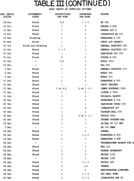
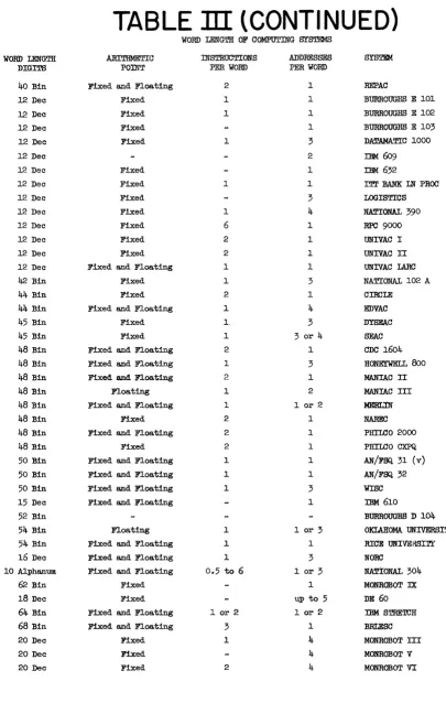
Word Length
multi-address codes), the command, and perhaps spares, tags, or check digits. For example, the ORDVAC utilizes 39 bits plus sign for an information word. One-half of a word, or 20 bits, is subdivided into a 12-bit address portion (for 4,096 high speed storage locations), a 6 bit command portion for 64 commands, and a 2-bit spare digit portion for special applications and versatility. The variation of word length among existing systems is rather wide. Table III shows the word lengths of the 222 systems
![TABLE ]I COMPUTlNG SYS~ MANUJ!AC1URED OR](https://thumb-us.123doks.com/thumbv2/123dok_us/963403.609549/44.617.105.556.94.665/table-i-computlng-sys-manuj-ac-ured-or.webp)