Fakult¨
at II, Department f¨
ur Informatik
Dissertation
Performance Optimising
Hardware Synthesis of Shared
Objects
von
Eike Grimpe
zur Erlangung des Grades eines Doktors
der Ingenieurswissenschaften
Zweitgutachter/Reviewer: Professor Dr. Wolfgang Rosenstiel
Tag der Disputation: 13. Mai 2005
c
Acknowledgements
Most of the ideas presented in this thesis have been developed while I was working for the EU project ODETTE (no. IST-1999-11476; funded by the European Commission under the 5th framework programm).
First of all, I would like to thank my supervisor, Prof. Dr. Wolfgang Nebel, who encouraged my work, and who was certainly more convinced than I that this dissertation will be successfully completed.
I am also grateful to Prof. Dr. Wolfgang Rosenstiel for his willingness to take the time to review this thesis.
Many thanks to those colleagues and individuals at the Kuratorium OFFIS e.V. and the Carl von Ossietzky University Oldenburg who took a share in enabling my work.
Last but not least, I would like to address special thanks to my former colleague Mustafa C¸ akır, who was a very good agony uncle when I was having hard times during the work on this thesis, and to whom, I am sure, I was a pain in the neck during this time.
Contents
Acknowledgements iii
1. Introduction 1
1.1. Motivation . . . 1
1.2. Contribution of this Thesis . . . 2
1.3. Thesis Outline . . . 3
2. Background and Related Work 5 2.1. Challenges in Concurrent Programming . . . 5
2.1.1. Synchronisation Primitives . . . 8
2.2. Shared Objects in Hardware Specifications. . . 11
2.2.1. Objective VHDL . . . 12
2.2.2. Shared Objects in SystemC: OSSS . . . 13
2.2.3. Shared Objects in this Work . . . 17
2.3. A Synthesis Semantics for Shared Objects . . . 18
2.3.1. Hardware Implementation of a Shared Object . . . 19
2.3.2. Hardware Implementation of the Client/Server Com-munication . . . 22
2.4. Problem Statement . . . 24
2.5. Examples . . . 27
2.5.1. Asynchronous Serial Transmitter/Receiver. . . 27
2.5.2. Arithmetic Logic Unit (ALU) . . . 30
2.6. Related Work . . . 32
2.6.1. Hardware . . . 32
3. System Representation and Analysis 39 3.1. Preliminaries . . . 40 3.1.1. Types . . . 40 3.1.2. Variables . . . 41 3.1.3. Constants . . . 41 3.1.4. Expressions . . . 42 3.1.5. States . . . 43 3.1.6. Semantics of Expressions . . . 43 3.1.7. Updates of States. . . 44 3.2. Syntax . . . 44 3.3. Semantics . . . 46 3.3.1. Transition System . . . 46 3.3.2. I/O Semantics . . . 50 3.4. System Representation . . . 51 3.4.1. Shared Objects . . . 51 3.4.2. Client Processes . . . 54
3.4.3. Communications between Clients and Shared Ob-jects . . . 55
3.4.4. Environment . . . 57
3.4.5. Putting it All Together . . . 57
3.4.6. Scheduling . . . 58
3.5. Assumptions . . . 58
3.6. Remarks. . . 60
4. Optimising the Shared Object Implementation 61 4.1. Refined Model of Guarded Methods . . . 63
4.1.1. Removing Communication. . . 66
4.1.2. Semantic Relationship BetweenGM and Tcf,ref(GM) . . . 67
4.2. Mutex and Nonmutex . . . 68
4.2.1. Efficient Calculation of Mutex Sets . . . 71
4.3. Synchronised and Unsynchronised Guarded Methods . . . 80
4.3.1. Synchronised Clients . . . 85
4.4. Optimised Implementations . . . 86
4.4.1. Static Parallelisation . . . 87
4.4.2. Omitting the Scheduler . . . 90
4.4.3. Direct Access . . . 93
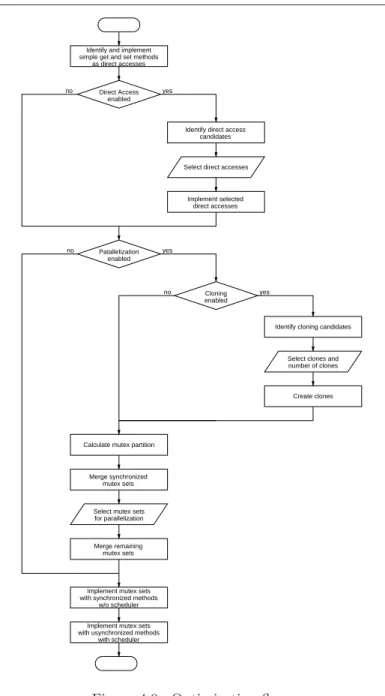
Contents 4.4.5. Performance vs. Area . . . 97 4.4.6. Optimisation Flow . . . 99 4.4.7. Example. . . 103 4.5. Outlook . . . 104 4.6. Summary . . . 104
5. Optimising the Client/Server Communication Protocol 107 5.1. Requests without Output Parameters . . . 109
5.1.1. Improved Protocol . . . 110
5.1.2. Asynchronous Message Passing . . . 114
5.1.3. Implementation of the Message Queue . . . 118
5.1.4. Preventing Out of Order Execution. . . 120
5.1.5. Sizing the Message Queues . . . 121
5.1.6. Comparison of the Protocols . . . 123
5.2. Requests with Output Parameters . . . 125
5.2.1. Splitting Requests . . . 129
5.2.2. Buffering Output Parameters . . . 135
5.3. Direct Access . . . 138
5.3.1. Missing Clock Cycle Boundaries . . . 140
5.4. Multiple Clock Domains . . . 142
5.4.1. Inferring a Shared Object’s Clock. . . 143
5.5. Summary . . . 144
6. Implementation and Experimental Results 147 6.1. The OSSS Pre-Processor. . . 147
6.1.1. Experimental Flow and Tool Environment . . . 150
6.2. Results for Example Transceiver . . . 151
6.2.1. Protocol Optimisations . . . 152
6.2.2. Parallelisation and Cloning . . . 160
6.2.3. Summary . . . 164
6.3. Results for Example Shared ALU . . . 165
6.3.1. Protocol Optimisations . . . 165
6.3.2. Parallelisation and Cloning . . . 168
6.3.3. Summary . . . 173
6.4. Runtime of the OSSS Pre-Processor . . . 174
A. Transition System 181
B. OSSS Implementation of Transceiver Example 183
C. Abstract Model of Transceiver Example 199
D. OSSS Implementation of ALU Example 211
List of Figures 219
List of Listings 223
Bibliography 225
Declaration of Original Work 235
1. Introduction
1.1. Motivation
Thanks to the ongoing technological advances in semiconductor manu-facturing and microelectronics, ever higher integration densities can be achieved for integrated circuits [59]. In consequence, more and more transistors and, hence, functionality can be integrated on the same sili-con area.
At the same time also the demand for ever more powerful microelec-tronic systems is steadily increasing. Even though the modern west-ern societies are already widely interspersed with embedded systems in nearly every aspect of life, the hunger for ever more computational power seems nearly insatiable, for instance, urged by new mobile and multimedia applications, highly sophisticated automotive and consumer electronics, and the vision of ubiquitous computing.
Unfortunately, the design productivity, which may be roughly defined as the number of transistors which can be designed by a human designer per time unit, is clearly outpaced by the technological progress, a devel-opment which is described as so called design productivity gap [47]. It means that the existing design methodologies and tools hardly provide the means to exploit the given technological possibilities and to meet the market requirements.
One approach to cope with this problem, and which is widely followed, is to raise the level of abstraction that can be applied in hardware design. In the past, raising the abstraction level, such as the step from hand-layouted circuits to gate level descriptions, and from gate level to register transfer level, usually also led to a boost in productivity. The last step into this direction is the one from register transfer level to behavioural or, more general, high level design and synthesis [26,73,62,60]. But despite all attempts to promote high level design and synthesis during the past years, the register transfer level is still the state-of-the-art design entry
for synthesis. One major reason why most high level synthesis products failed is the rather bad quality of the results they produced compared to a traditional register transfer level entry.
The failure of high level synthesis so far drastically illustrates one point; the quality of results, in terms of die area and performance, and to an increasing degree also power consumption, is crucial in hardware design. The silicon area occupied by a design is one major cost factor during its fabrication. Performance is a design constraint which has to be met, or a unique selling point against competing products. And power consumption is a limiting factor, particularly for mobile computing.
A somewhat more recent and still experimental approach to raise the level of abstraction in hardware design inspired by software engineering, and another flavor of high level modelling is the adoption of object-oriented design techniques, which is not yet supported by existing hard-ware description languages and synthesis tools. This work is based on such an approach.
The lesson learnt from high level synthesis is that the synthesis of digital circuits from higher level specifications, including object-oriented hardware specifications, must yield a quality of results which is nearly as good or even better than the results from traditional design entries to obtain acceptance.
1.2. Contribution of this Thesis
This thesis deals with the performance optimising hardware synthesis of shared objects in hardware specifications. A shared object is the in-stance of a user-defined data type which comprises some local data and operations to access and modify that data. Additionally, a shared ob-ject possesses built-in synchronisation capabilities which allow different concurrent entities to access it safely.
This thesis is based upon an earlier proposal for the hardware imple-mentation of shared objects which will serve us as a reference. To the best of our knowledge, it is the first and yet only practically applicable mapping from shared objects in object-oriented specifications as under-stood in this thesis to hardware.
The main problem addressed in this thesis is the research and de-velopment of alternative implementations for shared objects, which are
1.3. Thesis Outline more efficient, which means provide a better performance/area ratio, and/or which provide a higher absolute performance with respect to the reference implementation.
The main performance penalty with respect to the use of shared ob-jects is the delay which is caused to an accessing process by an access to a shared object owing to the necessary synchronisation between the process and the object. An increase in performance shall therefore be primary achieved by means of minimising this delay. The problem will be tackled in two ways, by
• optimising the implementation of a shared object itself such that the speed at which accesses are handled is increased;
• optimising the communication between shared objects and access-ing processes.
The ability to choose between different implementation alternatives for shared objects with different area and performance characteristics augments the design space by additional solutions, and may enable to pick a better or even optimal implementation for different design con-straints from the design space. The possibility to choose implementation alternatives which offer a higher performance also enlarges the potential application domains for shared objects towards applications, where per-formance and not area is the primary constraint.
In addition, synthesis technologies, which produce higher quality of results from shared objects, increase the acceptance of such higher level design entries and encourage their adoption, supporting the superior goal of increasing the design productivity.
1.3. Thesis Outline
Chapter2motivates the use of shared objects in hardware specifications, introduces the model of shared objects which is applied in this thesis, and presents those preliminary works this thesis is based upon, in particular, a synthesis semantics for shared objects which serves as a reference point. It also discusses some related work.
Chapter3provides a brief introduction to an abstract model of those systems we consider in this work and its formal semantics, which will be
used in chapter4to identify optimisations of a shared object implemen-tation which will not change its original semantics.
Chapter 4 discusses optimisations of the implementation of shared objects which primary aim at increasing the speed at which accesses to a shared object can be handled by exploiting parallelism.
Chapter 5is devoted to optimisations of the communication between a shared object and those concurrent processes that access it, with the goal to minimise the delay caused by an access to a shared object.
In chapter6 the integration of the optimisation techniques developed in the previous chapters into a synthesis front-end is briefly presented and some experimental results achieved with this implementation are given.
2. Background and Related
Work
This chapter should give the reader the necessary background to under-stand the motivation, origin, and context of the presented work.
The subject of matter of this thesis is the performance optimised im-plementation of shared objects which are used in hardware specifica-tions. A hardware specification in a hardware description language such as VHDL, Verilog, or SystemC is a concurrent program, which, usu-ally, describes a set of interacting parallel components. A shared object, as understood in this work, is a kind of synchronisation primitive, for the use in concurrent programs. The knowledge about the challenges in concurrent programming, and why synchronisation and synchronisation primitives are useful, as imparted in section 2.1, will therefore help to understand the application context of shared objects.
We will then proceed with rendering more precisely, what we mean with shared objects in the context of this work, in particular, with respect to their use in hardware specifications in section2.2.
Section2.3presents a synthesis semantics for shared objects that was developed in an earlier work, and which will be the starting point for the optimisations that we are going to develop in this thesis. In section 2.4
the problem statement will give the motivation and goal of those opti-misations.
Section2.5will illustrate the use of shared objects by means of two ex-amples, which will also serve us further in this work. Finally, section2.6
will give an overview of related work.
2.1. Challenges in Concurrent Programming
In concurrent programming [3,12, 18,21,50, 74] concurrent behaviour is usually explicitly expressed by means of threads, tasks, or processes.In this work we will prefer the term process. Operations within different processes are executed concurrently. Operations within one process are executed sequentially. If concurrent operations are executed on physi-cally distinct processors1, one talks of parallel execution. Alternatively,
concurrent operations may also be executed on the same processor. In that case they are sequentialised, for instance, by interleaving the op-erations of the concurrent processes. The term concurrency comprises both possible kinds of execution, and, from a functional point of view, it should ideally not make a difference, how concurrent processes are actually executed. We can also expect the components of a concurrent program to interact with each other, that is, to share data and resources, and to communicate with each other in order to achieve a common goal. Concurrency is a desirable feature in many applications. It permits applications, such as databases, information systems, or, more general, server applications, to be used by multiple users—orclients—at the same time. Concurrency makes it possible to share resources between different applications and to execute these applications“virtually” at the same time. And concurrency is a primary means to increase an applications’s performance, namely, by distributing concurrent parts of it to different physical processors which can operate in parallel
Unfortunately, the design and mastery of concurrent programs—re-gardless of describing hardware, software or both—is a challenging and error-prone task. The behaviour of concurrent programs is usually too complex to be fully understood by a human designer if the concurrency is not restricted somehow. But if the interaction of concurrent processes is not properly designed, intransparent, unexpected, and disastrous be-haviour could be the consequence. Take for instance the following simple program including two sequences of statements,CS1andCS2, which are
executed in parallel2 . S≡x:= 0; [CS1kCS2] with CS1≡y:=x;y:=y+ 1;x:=y CS2≡z:=x;z:=z+ 2;x:=z 1
The termprocessor in this context does not mean a microprocessor, but, more abstract, a computing resource which is able to run a single process at a time.
2
The notation S1;S2 means the sequential composition of programsS1 and S2,
2.1. Challenges in Concurrent Programming Dependent on the order in which the statements in the parallel parts are interleaved the value ofxmay be either 1, 2 or 3 after termination of S. In other words, the outcome of the program is nondeterministic. Nondeterminacy is a common characteristics of concurrent programs, and, in fact, the behaviour of a concurrent program can be simulated by a nondeterministic program. Although a concurrent program may partly behave nondeterministic, it is usually intended that, in the end, or at certain points, it yields deterministic results, or reacts to certain stimuli in a deterministic manner.
If, for the above example, the programmer wished the program to behave deterministically, he/she would have to ensure, that the programs
CS1andCS2are executed mutually exclusive. In that case the program
would always leave the value 3 inx.
Sequences of statements such as CS1 and CS2 which include
oper-ations on shared data/resources are called critical sections. Critical sections which refer to the same shared variables should be executed
mutually exclusivein order to guarantee a reliable access to an exclusive resource, and to avoid chaotic effects when operating on shared data. The question is now, how mutual exclusion can be actually achieved.
Soon after the first concurrent programming systems and parallel com-puters were developed, several solutions were proposed which tried to solve the mutual exclusion problem by using dedicated entry and exit protocols for critical sections [35, 65, 36]. These protocols ensure that only one process at a time enters its critical section. A known, well-studied, and often cited correct solution is Peterson’s algorithm [82]. Applying Peterson’s algorithm to the above program may yield the fol-lowing program:
SP eterson≡enter1:=false;enter2:=false;turn:=?mod2 + 1;
x:= 0;
[S1P etersonkS2P eterson]
with
S1P eterson≡enter1:=true;turn:= 2;
whileenter2∧turn= 1doskipod;
CS1;
S2P eterson≡enter2:=true;turn:= 1;
whileenter1∧turn= 2doskipod;
CS2;
enter2:=false;
Here, the correct use of enter1, enter2, and turn1 ensures thatCS1
and CS2 are executed mutually exclusive. This solution is also known
as Busy-Waiting—or Busy Wait—since each process continuously and actively monitors the entry condition to its critical sections by itself. Apart from mutual exclusion Peterson’s algorithm also guarantees fair-ness, starvation- and deadlock-freedom for two processes.
Synchronisation and mutual exclusion as demonstrated above reduce the nondeterminacy in a concurrent program. Even if a human de-signer does not fully understand the complex behaviour of a concurrent program, he/she can be sure that critical sections protected that way will leave shared data in a consistent state. Proper synchronisation is therefore a key to the design of reliable and less error-prone concurrent programs.
Even though Peterson’s algorithm, and similar solutions, can be also generalized for more than two processes one can already see, that it is neither very comfortable, nor safe, nor that it actually scales well with a growing number of processes that have to be synchronised this way. Managing the variables used for synchronisation, and implementing the entry and exit protocol are handcrafted tasks. Hence, programming er-rors, such as accidently using the wrong variable name, assigning the wrong value, and other, principally, minor programming errors are likely to happen, and can lead to intransparent and incorrect program behav-iour whose cause may be only hard to detect. For this reason synchro-nisation primitives were introduced with the goal to avoid these errors.
2.1.1. Synchronisation Primitives
Synchronisation primitives [4, 19] are higher level constructs—elements of a programming language, supported by appropriate mechanisms pro-vided by an operating system, or runtime environment—which provide means to achieve mutual exclusion as illustrated in the previous section, but without having to explicitly implement the entry and exit to critical
2.1. Challenges in Concurrent Programming sections as complicated. Synchronisation primitives do therefore greatly ease the task of designing the interaction between concurrent processes, and to control the access to shared resources.
The key concept which nearly all synchronisation primitives have in common and are based on is an atomic test and set operation. Such an operation allows for reading and updating the value of a variable in one indivisible step, such that no other concurrent process can interfere. A variable which supports atomic test and set is usually called asemaphore, after Dijkstra who first introduced this concept [37, 36]. A semaphore is a positive integer variable on which two operations,PandV, are de-fined. Given a semaphores,P(s) delays the invoking process untils >0 and then executes s:=s−1. The test and decrement are executed as an indivisible operation. Likewise, V(s) executess:=s+ 1 as an indi-visible operation. Based on semaphores, SP eterson can be reformulated as follows:
SSemaphore ≡sem:= 1;x:= 0; [S1SemaphorekS2Semaphore]
S1Semaphore≡P(sem) CS1; V(sem); S2Semaphore≡P(sem); CS2; V(sem);
Obviously, this solution is much simpler and less error-prone than Peterson’s algorithm, since the complex entry and exit protocols are replaced by simple operations on a semaphore. A further advantage is the symmetry of this solution; both processes use the same semaphore and exactly the same operations to guard their critical sections. Further processes with critical sections referring to the same variables could be simply added, in the same style, without having to modify the existing processes, and without having to introduce further variables. Even the same semaphore can be used.
Even though semaphores are already a significant improvement com-pared with completely handcrafted solutions such as busy waiting, and
can, in principle, serve to implement any kind of synchronisation between parallel processes with shared variables, they are still rather unstructured and low level primitives; a misplaced or missing Por V operation, an accidental mix-up ofP and V, or accidently using a wrong semaphore in one of these operations can have a disastrous effect. Hence, a couple of synchronisation primitives evolved from semaphores, as depicted in Figure 2.1, comprising critical regions [48, 49, 54], monitors [53], path expressions [25,24], message passing, andremote procedure calls which aim at avoiding these problems, and which stepwise enhanced modular-ity, ease of use, and expressive power.
Path Expressions
Remote Procedure Call
Message Passing Monitors Critical Regions Semaphores Busy−Waiting ORIENTED PROCEDURE ORIENTED MESSAGE
Figure 2.1.: Synchronisation techniques (adopted from [4]). In the following the concept of a monitor will be most important for us. A monitor comprises some local data—i.e. local variables—and a set of methods operating on that data. Access to the local data is only possible via the methods it provides for this purpose, and which are executed mutually exclusive. Hence, only one concurrent process can enter to a monitor at a time, and the consistency of the local data is en-sured. Most monitor implementations additionally provide for condition synchronisation by means of a so called guardwhich can be associated with a method. The execution of a method such guarded will be possi-ble, only if the associated condition is satisfied, otherwise the invoking
2.2. Shared Objects in Hardware Specifications process will be blocked.
A shared object is not a synchronisation primitive in the original sense like the ones mentioned above, and it is not a term with a fixed and un-ambiguous meaning. First of all, a shared object is just an object, in the object-oriented or object-based meaning, which is shared between concurrent processes or other concurrent objects. Consequently, differ-ent distributed and concurrdiffer-ent programming languages often have dif-ferent notions of shared objects. However, despite the differences, all approaches do obviously have to deal somehow with concurrent accesses to a shared object, and, therefore, with synchronisation. And one pos-sibility to deal with it is to consider shared objects a kind of monitor, a view that we will apply in this thesis, and which will be engrossed in the following.
2.2. Shared Objects in Hardware Specifications
Hardware is by nature parallel, hence, hardware description languages are usually concurrent programming languages, and a hardware specifi-cation in one of these languages is basically a concurrent program. The design of such programs poses, principally, the same challenges as the design of concurrent software programs, hence, the availability of high level synchronisation primitives would provide similar benefits.Nevertheless, the most widely used hardware description languages VHDL and Verilog do not provide higher level synchronisation mecha-nisms, or, if available, they are not supported for synthesis. Moreover, with respect to their abstraction level these hardware description lan-guages are, in general, one step behind software programming lanlan-guages. But facing an ever increasing design complexity also the demands for higher levels of abstraction in hardware design are increasing. For that reason attempts were made over the past years to develop object-oriented hardware description languages or to extend existing ones ac-cordingly [91, 92, 95, 88, 96, 10], since object-orientation has proved quite successful in software engineering, but is still missing in existing hardware description languages. Presently, all these works are still topic of research.
With the combination of object-orientation and concurrent program-ming in hardware specifications also the question arises, if and how to
deal with shared objects, particularly including the question what their synthesis semantics should be. To the best of our knowledge, the only works which sufficiently deal with this question and provide a possible answer are those researches, which are presented in the following sec-tions, and on which this work is based upon.
2.2.1. Objective VHDL
Objective VHDL [86, 85, 87, 88, 83] is an object-oriented extension of VHDL which was developed mainly in the course of the European ESPRIT IV project REQUEST [75]. Objective VHDL’s main contribu-tion to VHDL is a class concept which allows the user to model new data types by means of classes, like in C++ or Java. That makes it also pos-sible to declare signals and shared variables, whose type is a class type, which lead to the question what meaning such shared objects3
would have, if used by concurrent processes. The answer to this question was a model adopted from Ada95’s protected objects (cf. section 2.6.2); a monitor-like object which provides for mutual exclusive access, and con-dition synchronisation.
Listing 2.1 on the next page illustrates the declaration and usage of a shared object in Objective VHDL. The use of ’CLASS indicates that TransceiverInterface is a class type. The attribute SCHEDULING spec-ifies which scheduling policy shall be applied to concurrent accesses. As common in object-oriented languages, a method of a shared object is invoked by specifying the object and the method to be invoked sepa-rated by a dot. A language implementation must ensure that concurrent method invocations are sequentialised according to the specified schedul-ing policy and, thus, are executed mutually exclusive. Objective VHDL also provides for condition synchronisation by allowing for associating a Boolean expression, the guard, with each method provided by a shared object.
What makes Objective VHDL unique compared with other attempts to provide object-oriented hardware description languages is, that its development put a clear focus on synthesisability, hence, the proposed language extensions were accompanied by appropriate—but not
neces-3
Note, that such objects were never explicitly called shared objects in Objective VHDL.
2.2. Shared Objects in Hardware Specifications sarily optimal—synthesis semantics. Such a synthesis semantics was also proposed for shared objects, and is described in section2.3.
−− w i t h i n VHDL a r c h i t e c t u r e : s h a r e d v a r i a b l e t r c v i f : T r a n s c e i v e r I n t e r f a c e ’ CLASS ; a t t r i b u t e SCHEDULING : S t r i n g ; a t t r i b u t e SCHEDULING o f t r c v i f : v a r i a b l e i s ”RoundRobin ” ; P1 : process i s −− l o c a l v a r i a b l e d e c l a r a t i o n s begin . . . t r c v i f . send ( b y t e ) ; . . . end P1 ; P2 : process i s −− l o c a l v a r i a b l e d e c l a r a t i o n s begin . . . b y t e := t r c v i f . r e c e i v e ( ) ; . . . end P1 ;
Listing 2.1: Usage of shared objects in Objective VHDL. With the upcoming of SystemC, a C/C++ based hardware descrip-tion language, the interest in Objective VHDL dramatically dropped and, meanwhile, the further development of Objective VHDL came to a complete stop. It is not expected that it will be ever continued. A prototypic pre-processor, which maps an Objective VHDL specification to standard VHDL is the only Objective VHDL based tool that was developed up to the present date. A native Objective VHDL simulator does not exist. However, the works on Objective VHDL are the basis for similar works on SystemC which are discussed in the next section.
2.2.2. Shared Objects in SystemC: OSSS
SystemC [15,46] is a public available C++ class library which provides constructs that are necessary for modelling hardware, but which are missing in C++. These constructs include hardware-like data types, such as arbitrary-precision integer types, bits and bit-vectors, logic types, etc.,
processes representing parallel behaviour, modules representing hard-ware entities, and signals and ports which are used to establish commu-nication between processes. SystemC also introduces a model of time, including the ability to model clocks and synchronous processes, and a complex synchronisation model. Altogether, the SystemC class library adds most of the features to C++ which can be found in hardware de-scription languages such as VHDL and Verilog. It also includes a built-in simulation kernel, such that each SystemC description can be simply compiled with a common C++ compiler in order to obtain an executable simulation model.
SystemC’s original purpose was to serve as a modelling language for creating fast simulation models, but not necessarily, to serve as a design language for creating synthesis models. However, the SystemC syntax and semantics are quite similar to VHDL, such that synthesis, at least for a language subset, should principally not be more complicated than for VHDL. Indeed, a first SystemC synthesis tool, the CoCentric Sys-temC CompilerTM4 from Synopsys, followed not long after SystemC’s
first public appearance. Further SystemC synthesis tools, such as the
CynthesizerTMfrom Forte Design Systems, were recently released, or are
announced for the near future.
The CoCentric SystemC Compiler accepts only a subset of SystemC/C++. This subset is semantically and syntactically widely equivalent to VHDL’s and Verilog’s supported synthesis subsets. In par-ticular, it excludes most of C++’ object-oriented features. Although the implementation of SystemC itself makes intensive use of these features, the SystemC language constructs are obviously simply treated as key-words. That means that the CoCentric SystemC Compiler is actually not able to handle user-defined object-oriented C++ elements.
It suggested itself to apply the synthesis concepts developed for Objec-tive VHDL to SystemC in order to extend its synthesis subset; an under-taking which was addressed within the European IST project ODETTE [79]. Its main results were the definition of an extended— w.r.t. to the CoCentric SystemC Compiler—SystemC synthesis subset, called OSSS (ODETTE System Synthesis Subset) [41, 44, 42, 45, 43], and a prototypic pre-processor (cf. chapter6). The pre-processor
trans-4
Meanwhile, the further development of the CoCentric SystemC Compiler was an-nounced to be stopped.
2.2. Shared Objects in Hardware Specifications forms an OSSS based specification into a SystemC or VHDL specifi-cation, which can be further handled by third-party tools, such as the CoCentric SystemC Compiler.
Newer tools, such as Forte’s Cynthesizer, are said to support a larger subset of SystemC/C++. But these tools were released after the ODETTE project had ended, and, to the best of our knowledge, they still do not provide support for shared objects or any comparable feature. SystemC does not provide the notion of shared objects in the same way as Objective VHDL does. In principle, one could just declare an ordi-nary object in a place, where it could be accessed by different concurrent processes, but such an object would not reveal a realistic hardware-like simulation semantics. For that reason OSSS introduces shared objects as an extension to SystemC. Like SystemC itself, this extension is pro-vided by a free C++ class library built on top of SystemC. Apart from a few other extensions dealing with polymorphism, this class library pro-vides a bit- and cycle-accurate simulation model for shared objects, and constructs that are necessary to declare and handle shared objects.
The code snippet used in the previous section, but implemented in OSSS would look as follows:
// w i t h i n SC MODULE: sc shared< RoundRobin , T r a n s c e i v e r I n t e r f a c e > t r c v i f ; void P1 ( ) { . . . SC RPC( t r c v i f , send ( b y t e ) ) ; . . . } void P2 ( ) { . . . SC RFC( byte , t r c v i f , r e c e i v e ( ) ) ; . . . }
Listing 2.2: Usage of shared objects in OSSS.
The three new ‘keywords’ sc shared, SC RPC and SC RFCbelong to the extensions provided in OSSS. Actually,sc sharedis a class tem-plate used to declare a shared object. Similar to Objective VHDL, the
declaration requires to specify a scheduling policy which is used to han-dle concurrent accesses. In this example around robinscheduling policy is chosen. The OSSS class library already includes some common sched-ulers, but supports also user-defined ones. TransceiverInterface identi-fies a user-defined class, which actually implements the behaviour of the shared object.
The class templatesc sharedcan be seen as a wrapper whose purpose is to add the proper simulation behaviour, which means, in particular, the correct invocation of the scheduler, and the correct simulation of the client/server communication protocol which will be synthesised from a remote method invocation. SC RPCand SC RFCare macros which are used to invoke the methods provided by the shared object;SC RPC for procedures and SC RFCfor functions. Both remote method invo-cations are blocking.
The declaration of class TransceiverInterface is sketched by the follow-ing code. The complete declaration is included in AppendixB.
template< unsigned i n t SBUFFSIZE = 1 , RBUFFSIZE = 1 >
c l a s s T r a n s c e i v e r I n t e r f a c e
{
public:
T r a n s c e i v e r I n t e r f a c e ( ) ; SCGUARDED( sBuffEmpty ,
void, send ( const s c b i g i n t< 8 > & ) ) ; SCGUARDED( ! rBuffEmpty , s c b i g i n t< 8 >, r e c e i v e ( ) ) ; . . . protected: bool sBuffEmpty ; bool rBuffEmpty ; s c b i g i n t< 8 > s B u f f ; s c b i g i n t< 8 > r B u f f ; . . . };
Listing 2.3: Declaration of class TransceiverInterface.
The only difference to a common C++ class declaration is the use of the construct SC GUARDED, which is provided in OSSS to associate a guard condition with a method. In principle, any kind of user-defined C++ class can be used as a shared object. Only, each method of such a class which is externally invoked must be declared as a guarded method.
2.2. Shared Objects in Hardware Specifications In contrast to Objective VHDL, each OSSS specification, like each SystemC specification, can be simulated without the need for a specific simulator, by compiling it with an off-the-shelf C++ compiler, and run-ning the executable5.
2.2.3. Shared Objects in this Work
The notion of shared objects which is used in this work is directly derived from the model that is basically shared by Objective VHDL and OSSS. We can summarize its main characteristics as follows:
• A shared object consists of a set of local variables together with a set of procedures and functions which operate on those variables. We will refer to the set of variables also as thedata membersof a shared object, and to its functions and procedure asmethods.
• The data members of a shared object must be used only by its methods.
• The set of methods provided by a shared object for external use is called itsinterface. Interaction with a shared object is only allowed through this interface.
• Concurrent accesses to a shared object are synchronised by some mechanism. Any such synchronisation mechanism ensures that concurrent requests leave a shared object always in a consistent state. Enforcing mutual exclusive execution of all concurrently requested methods is one, but not the only possible solution that satisfies this requirement.
• A shared object is passive, which means it is not able to initiate any action by itself without being externally triggered.
• Methods of a shared object can have an associated guard condition. The guard condition may involve members of a shared object and input parameters of the method. Calls to guarded methods may be accepted, only if the guard evaluates totrue. Otherwise the call will be delayed up to that point. The guard mechanism ensures, that the guard condition does not change between its evaluation
5
Provided the specifications are syntactically and semantically correct with respect to the language definitions.
and the execution of the method it is associated with. Methods for which a guard condition is not explicitly specified are assumed to have the guard condition true, which means they can always be invoked.
• A shared object is declared in a scope, where it could be shared between concurrent processes.
• No request to a method gets lost. Requests by the same client must be served and completed in the same order they were issued. Any parameters returned by a method invoked on a shared object must be available before their first use.
• No method of a shared object must invoke a method of another shared object but itself. Nested method invocations are executed unsynchronised.
• A guarded method execution, once started, can not be interrupted. The exact latency of a guarded method execution and the total delay caused by a request must be regarded as unknown.
We call a process which contains a request to a method of a particular shared object aclientor client processof that object. Likewise, we may also refer to a shared object as a server, and to the methods provided by a shared object as services.
According to the characteristics listed above, shared objects consid-ered in this thesis are like monitors. In fact, we mentioned previously that this model is originally based on Ada95’s protected objects, which are themselves rather like monitors. Already Hoare applied Simula67’s class notation for describing monitors, but seemingly for the sake of the notational style, but without object-oriented features like inheritance or polymorphism fostering his decision. Nevertheless, although not being essential, these features are obviously quite useful for modelling, which was, after all, a major motivation to base shared objects on an object-oriented model.
2.3. A Synthesis Semantics for Shared Objects
Since we are intending to use shared objects in hardware specifications which shall be input to an automated synthesis process, we are now going2.3. A Synthesis Semantics for Shared Objects to clarify, what the synthesis semantics of a shared object is. Synthesis semantics means here a mapping of a shared object to a functionally equivalent representation at RT or Behavioral level, which can be further processed by third-party tools.
Our basis will be a synthesis semantics for shared objects that was proposed by Radetzki [84]. Its development was originally closely cou-pled with, but no limited to, the development of Objective VHDL. In principle, it is applicable to any kind of object, regardless in what lan-guage, which adheres to the characteristics listed in the previous sec-tion. To the best of our knowledge it is the first, and, up to the present date, only practically applicable synthesis semantics for shared objects, or monitor-like concepts. Its practical applicability was proved by means of prototypic pre-processors for Objective VHDL and OSSS.
The synthesis semantics has basically two aspects, for which we will discuss separate optimisations later: the implementation of the shared object itself, and the implementation of the client/server communication.
2.3.1. Hardware Implementation of a Shared Object
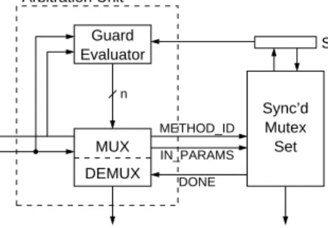
The hardware implementation of a shared object according to [84] is illustrated by the following Figure 2.2.
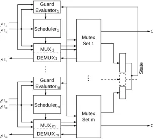
MUX DEMUX Arbitration Unit 1...n IN_PARAMS 1...n METHOD_ID 1...n DONE METHOD_ID IN_PARAMS DONE Scheduler Guard Evaluator Server Process State OUT_PARAMS RESET CLK
The implementation consists of four major functional blocks; a sched-uler, the guard evaluation unit, a multiplexing/demultiplexing unit, and a server.
The guard evaluation unit contains the implementations of the guard expressions associated with the methods of a shared object. The sched-uler will determine which request to grant next, if there are any active requests, and will take for its decision also the input from the guard evaluation unit into account. The scheduler, in turn, controls the multi-plexing/demultiplexing unit, which switches between the communication channels (cf. following chapter) that connect each server with its clients. The guard evaluation unit and multiplexing/demultiplexing unit are im-plemented as combinational components, and the scheduler as combi-national or asynchronous sequential component, together forming the arbitration unit of a shared object.
The requested methods are finally executed by the server component. It is implemented by a single synchronous process containing the imple-mentations of all the methods provided by the shared object.
The state of a shared object, which is held in a single register and which is also depicted in the above figure, is generated from the data members of the shared object; each original data member is represented by a distinct bit-slice of the state register.
All requests to a shared object are served mutually exclusive. The scheduling policy that is applied to concurrent requests has to be in-cluded in the specification of a shared object as demonstrated for Ob-jective VHDL (cf. section2.2.1) and OSSS (cf. section2.2.2).
Listing 2.4 illustrates the general structure of the VHDL implemen-tation of a sever process. It follows the coding guidelines for Synopsys’ Behavioral CompilerTM[62,93]. Thus, behavioural synthesis can be
ap-plied to the generated server process, if desired.
It turned out that the same coding style is also accepted by Synop-sys’ Design CompilerTM. But if the specification of the server process is
handed over to this tool, no scheduling will be applied, and the sched-ule will be fixed as included in the description. However, by generating a structure which fits both synthesis technologies, it is finally the de-signer’s choice, which one to apply. Applying behavioral synthesis may be useful, if the provided methods are of a complex nature, and are not yet completely scheduled.
2.3. A Synthesis Semantics for Shared Objects SERVER : process i s
−− l o c a l v a r i a b l e d e c l a r a t i o n s
begin
RESET LOOP : loop
−− i n i t i a l i s a t i o n o f t h e s h a r e d o b j e c t ’ s s t a t e
wait u n t i l CLK’ e v e n t and CLK = ’ 1 ’ ; e x i t RESET LOOP when RESET = ’ 1 ’ ; MAIN LOOP : loop
case METHOD ID i s when METHOD 1 => DONE<= ’ 0 ’ ; −− copy i n p u t parameters , i n t o l o c a l v a r i a b l e s −− copy used s t a t e v a r i a b l e s i n t o l o c a l v a r i a b l e s −− method i m p l e m e n t a t i o n wait u n t i l CLK’ e v e n t and CLK = ’ 1 ’ ; e x i t RESET LOOP when RESET = ’ 1 ’ ;
−− r e t u r n parameters , i f any when . . . when METHOD N => DONE<= ’ 0 ’ ; −− copy i n p u t parameters , i n t o l o c a l v a r i a b l e s −− copy used s t a t e v a r i a b l e s i n t o l o c a l v a r i a b l e s −− method i m p l e m e n t a t i o n wait u n t i l CLK’ e v e n t and CLK = ’ 1 ’ ; e x i t RESET LOOP when RESET = ’ 1 ’ ;
−− r e t u r n parameters , i f any
when others =>
a s s e r t SELECT METHOD = NO REQ report ” i l l e g a l method ID” s e v e r i t y f a i l u r e ;
wait u n t i l CLK’ e v e n t and CLK = ’ 1 ’ ; e x i t RESET LOOP when RESET = ’ 1 ’ ; next MAIN LOOP ;
end case; DONE<= ’ 1 ’ ;
−− u p d a t e s t a t e
wait u n t i l CLK’ e v e n t and CLK = ’ 1 ’ ; e x i t RESET LOOP when RESET = ’ 1 ’ ; end loop MAIN LOOP ;
end loop RESET LOOP ; end SERVER;
Listing 2.4: VHDL code template for sever process.
METHOD 1. . . METHDOD N are constants—e.g. integer constants— which unambiguously identify each method provided by a shared object
and are generated during synthesis. NO REQ is a constant which is assigned, if there are actually no active requests. The signal DONE is used in the client/server communication, which is briefly presented in the subsequent section.
2.3.2. Hardware Implementation of the Client/Server
Communication
According to [84] a remote method invocation is mapped to a synchro-nous communication between a client and a server following a simple handshake protocol. Physically, the communication takes place over dedicatedchannelswhich connect clients and servers, and which consist of the signals and busses which are illustrated in Figure2.3.
DONE METHOD_ID
IN_PARAMS
OUT_PARAMS
Client Server
Figure 2.3.: Channel connecting client and server.
METHOD ID and IN PARAMS are signals, from a client to a server. METHOD ID identifies the method to be invoked. As mentioned in the previous chapter, to each method provided by a shared object a unique constant is assigned during synthesis. IN PARAMS is used to pass any input parameters required by the requested method to the server.
DONE and OUT PARAMS are signals, or busses, respectively, from a server to a client. OUT PARAMS is a bus that is used to pass any output parameters of the invoked method back to the invoking client, and DONE is used to establish a handshake between a client and a server. All clients of a particular shared object share the same OUT PARAMS bus—recall, that all methods are executed under mutual exclusion—, while METHOD ID, IN PARAMS and DONE are unique per client/server pair.
Over these channels a simple handshake protocol establishes the com-munication between clients and severs. A VHDL template for this
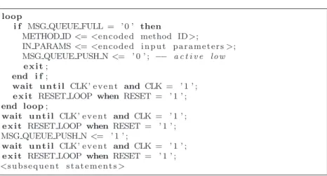
pro-2.3. A Synthesis Semantics for Shared Objects tocol is given in the following listing2.5. As for the server process (cf. previous section), the coding style is according to the coding guidelines for Synopsys’ Behavioral Compiler, but is as well accepted by the Design Compiler. A timing diagram is included in chapter5.
METHOD ID<=<encoded method id>;
IN PARAMS<=<encoded i n p u t p a r a m e t e r v a l u e s>; loop −− w a i t f o r acknowledgement : DONE( ’ 1 ’ −> ’ 0 ’ )
i f DONE = ’ 0 ’ then METHOD ID<= NO REQ;
e x i t; end i f;
wait u n t i l CLK’ e v e n t and CLK = ’ 1 ’ ; e x i t RESET LOOP when RESET = ’ 1 ’ ; end loop;
wait u n t i l CLK’ e v e n t and CLK = ’ 1 ’ ; e x i t RESET LOOP when RESET = ’ 1 ’ ;
loop −− w a i t f o r c o m p l e t i o n o f r e q u e s t : DONE( ’ 0 ’ −> ’ 1 ’ )
i f DONE = ’ 1 ’ then
−− r e t r i e v e o u t p u t parameters , i f any , from OUT PARAMS
e x i t; end i f;
wait u n t i l CLK’ e v e n t and CLK = ’ 1 ’ ; e x i t RESET LOOP when RESET = ’ 1 ’ ; end loop;
wait u n t i l CLK’ e v e n t and CLK = ’ 1 ’ ; e x i t RESET LOOP when RESET = ’ 1 ’ ;
<s u b s e q u e n t s t a t e m e n t s>
Listing 2.5: VHDL code template for na¨ıve protocol.
Each remote method invocation statement in a client process is replaced by this protocol during synthesis.
The protocol comprises different phases. In the first phase a client process initiates a request by assigning the proper ID of the method to be invoked to METHOD ID, and, all necessary input parameters to IN PARAMS. Next, the client waits for the addressed server to ac-knowledge its request. The server signals an acac-knowledgement with a falling edge on DONE, as soon as it starts the execution of the requested method. The period of time from the issuing of a request until its accep-tance is, in general, not fixed and unpredictable. If and when a server accepts a request depends on several factors, including its own state which may be used in a guard condition associated with the requested
method, the state of the scheduler, and any concurrent requests from other clients. It may be even possible that the client will wait forever.
However, if the acceptance of the request is eventually acknowledged, the client reacts immediately by de-assigning METHOD ID in order to prevent the request to be served another time.
In the final phase, the client waits until the server has finished the execution of the requested method, which is signalled by a rising edge on DONE, and receives any returned values via OUT PARAMS. This final synchronisation ensures that the protocol also works properly for methods with unknown latency. More details can be taken from [84].
2.4. Problem Statement
Area and timing, or, more precisely, performance, are the most crucial non-functional properties in hardware design. Area is a major cost fac-tor, while a high application performance is normally one of the primary design goals. Hence, the quality of the synthesis results (QoR) could, in principle, be measured by means of the relative performance (per area), that is, the ratio perf ormancearea ; the larger this ratio for a given and fixed area or performance, the higher the QoR and the efficiency of the synthesis process6.
Of course, efficiency is also crucial for the implementation of shared objects. That means we are interested in any optimisations on the im-plementation presented in the previous section, which either provide a higher performance for the same area, or require less area for the same performance—or even less area and higher performance at the same time. From an area point of view the proposed implementation is already a quite good solution, while, from a performance point of view, it is the opposite; the sequentialisation of requests allows all methods provided by a shared object to share the same resources, while it represents the slowest possible solution to handle concurrent requests. Therefore, it is our first goal to find possible optimisations which increase the perfor-mance of the implementation presented in the previous section, but not its area.
6
Assuming that implementations with a larger ratio are still a correct model of the specification.
2.4. Problem Statement We will later see that we can, in fact, find such optimisations, which means that the original implementation incorporates some unnecessary synchronisation overhead, wherefore we will refer to it as the na¨ıve im-plementationin the remainder of the thesis.
Sometimes, not the relative performance but just the absolute per-formance counts, which means that one is willing to accept increased area, and, possibly, even a decreased relative performance, as price for achieving a higher absolute performance. It is therefore our second goal to find alternative implementations of shared objects which provide a higher absolute performance, even at the cost of additional area.
That leads to the question, in which aspect, in general, the imple-mentation of shared objects can be improved in order to increase perfor-mance, or, the other way around, where to find performance penalties which could be decreased? The main performance penalty with respect to to shared objects is the amount of time the operations following a re-quest to a shared object are delayed because of the rere-quest, or, in other words, the amount of time a client is engaged in synchronisation with a shared object.
Definition 2.1 (Delay of a request) The delay or delay timeδ(ri)of a requestriis the amount of time by which the start time of an operation
following the request ri is delayed from the start time of an operation
before the request because of the request. For synchronous processes it is the number of clock cycle steps by which the starting time of an operation
following request ri is delayed by that request. 2
In order to increase performance, we will therefore aim at reducing the delay induced by a request. Note, that this does not necessarily mean that the delay time for each individual request actually has to be reduced. Owing to subtle process interaction, and the nondeterminacy of the considered systems, some optimisations could, in principle, even lead to an increased delay time for an individual request. But, generally, when observing a system’s behaviour over a sufficiently long period of time, we aim at reducing the average delay time over all these requests. The delay for a particular request ri, is basically comprised of three factors:
tcsCommP rot represents the delay which is induced by the client/server communication protocol assuming that the request is enabled—i.e. the guard condition evaluates to true—, and does not collide with any other concurrent request. It can therefore be regarded as the pure protocol overhead.
tcollision represents the delay which is caused because a client has to wait for other concurrent requests to be served first.
And, finally,tdisabledrepresents the time a request is delayed because of condition synchronisation, that is, because the guard of the requested method is false. We will not be able to influence this time directly, such that we treat it as an unknown remainder, which will not be taken into further consideration.
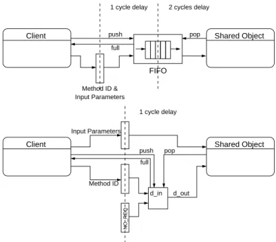
The timestcsCommP rotandtcollision, and the resulting delay timeδ—7 clock cycles in this example—are depicted in the following Figure 2.4. More details on the communication between a client and a server are given later.
request by another client is served 1 request completed 2 request δ Object Shared Client 10 9 8 7 6 3 4 5 (# clock cycles) Time blocked/idle active tcsCommProt tcollision
Figure 2.4.: Delay caused by a request.
The reduction oftcollisionis addressed in chapter4, while the reduction oftcsCommP rotis addressed in chapter 5.
As a matter of course, any optimisation applied to the na¨ıve imple-mentation shall not change its functionality, which means, its semantics.
2.5. Examples In other words, if the na¨ıve implementation of a shared object is a model for a given specification, so shall be each optimised implementation. We will render this more precisely in the following chapters.
2.5. Examples
In the following we will introduce two example designs, which make use of shared objects, and which will also serve us in the remainder of this work for illustrative purposes, as well as for the evaluation of the proposed optimisations. Full implementations of both examples in OSSS can be found in AppendixBand D, respectively.
The examples illustrate the two main application scenarios for shared objects; the transceiver example demonstrates their use in interprocess communication/synchronisation, while the ALU example demonstrates their use as shared resources.
2.5.1. Asynchronous Serial Transmitter/Receiver
A serial transceiver (transmitter/receiver), such as the RS232 UART, which can still be found in various PCs and peripherals, enables a serial communication between different components. Its main job can be seen to be the conversion of a parallel transmission into a serial transmission, and vice versa. Parallel data, usually a byte, is given to a transceiver and sent bit for bit over a single line. A receiver converts the bit stream back into a parallel datum. Asynchronous transmission means that the sender and receiver synchronise with each other by means of dedicated start and stop bits. In contrast, in a synchronous transmission sender and receiver are synchronised by an additional clock signal—the shift-or bit-clock—. Most serial transceivers provide fshift-or the possibility to choose between different transition modes, and baudrates, and provide also some error detection and correction capabilities.
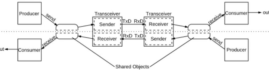
The setup we use in this example as illustrated in Figure 2.6 is con-structed of two symmetrical sides; each side consists of a transceiver, a shared object, a producer, and a consumer. The producer generates data and sends it via the transceiver, while the consumer obtains data from the transceiver for further processing. The shared object serves as a comfortable interface to the transceiver. The transceivers we use in our
Received Data Status Control Transmitted Data TxD RxD Receiver/Transmitter Asynchronous
Figure 2.5.: Asynchronous receiver/transmitter.
experiment provide separate processes for sending and receiving, and are therefore capable to operate in full duplex mode. Both sides of the de-sign are connected through their transceivers, such that each consumer receives data from the producer on the opposite side. In this example the data being exchanged does not have any special meaning; one pro-ducer simply produces even numbers, while the other one produces odd numbers. Sender Receiver Receiver Sender Transceiver Transceiver RxD TxD TxD RxD output Shared Objects (Transceiver Interface) output send receive receive send Producer Consumer Consumer Producer
Figure 2.6.: Experimental setup for Transceiver.
The shared object forming the transceiver’s interface basically pro-vides the method interface that is given in Figure2.7(some methods are omitted). We use the notationg→methodas a signature for a guarded method, withg being the guard. Primarily, the producers use the send method to write a byte to the send buffer (sBuff), and the consumers use the receive method to read a byte from the receive Buffer (rBuff). The transceiver uses putRBuff to write a byte to the receive buffer, and getSBuff to get a byte from the send buffer. The guard conditions will ensure, that reading, or writing, respectively, to a buffer is only enabled, if the buffer is not empty, or full, respectively.
2.5. Examples
!sBuffFull send( Byte )
!sBuffEmpty getSBuff() : Byte !rBuffEmpty receive() : Byte
!rBufferFull putRBuff( Byte )
...
true getBaudrate() : Unsigned true receiverEnabled() : Boolean
: TransceiverInterface
Figure 2.7.: Methods provided by the transceiver interface. A simulation run of the system before synthesis at a rate of 1 bit/16 clock cycles at a 33MHz clock rate—which gives a gross baudrate of roughly 2MBit/s—, is shown in Figure 2.8, spanning approximately 34µs. The waveform shows the state of the two serial lines connect-ing the transceivers (line1, line2), and the data sampled by the two consumer processes (output1, output2).
Figure 2.8.: Simulation run of transceiver example.
The transceiver is a good example for shared objects as a means for modelling interprocess communication. In this experimental setup we have two pairs of communicating process: each producer process com-municates with the sender process of the transceiver it is connected to, and each consumer process communicates with the receiver process of the transceiver it is connected to.
2.5.2. Arithmetic Logic Unit (ALU)
An arithmetic logic unit, or ALU for short, (cf. Figure 2.9) is a com-mon functional unit which is able to perform different arithmetic and logic operations, such as addition, shift, or conjunction, on the operands passed to it. ALU op_1 op_2 select_operation result flags
Figure 2.9.: Arithmetic Logic Unit (ALU).
We will use the ALU as a model for a shared resource, whose services— the arithmetic and logic operations it provides—are concurrently used by a set of parallel processes. In contrast to the previous example, this time a shared object is not simply used as an interface to another hardware component, but it provides the complete functionality of the ALU itself. The experimental setup comprises the ALU and two client processes which concurrently use its services as illustrated in Figure 2.10. The clients are computing the square roots of integer numbers according to Newton’s iteration [77]; one client computes the square roots of even integer numbers, the other one computes the square roots of odd integer numbers. For their computations the clients invoke the multiplication, division, subtraction, and addition functions provided by the ALU. The ALU implements arbitrary precision fixed point arithmetics.
result result op, params op, params (ALU) Shared Object Client 2 Client 1
Figure 2.10.: Experimental setup for shared ALU.
2.5. Examples by means of repeated shift and addition, and shift and subtraction op-erations, respectively, and therefore takenclock cycles for execution for an n bit wide multiplier, or, divisor, respectively. Newton’s iteration is an approximation method which converges to the result with varying speed, dependent on the input and chosen precision, such that also the latency of the whole algorithm varies.
The ALU provides the following public interface7
:
true div( sc_fixed<WL, IWL> a, b ) : sc_fixed<3*WL−2*IWL,2*WL−IWL> true add( sc_fixed<WL, IWL> a, b ) : sc_fixed<WL+1 ,IWL+1> true sub( sc_fixed<WL, IWL> a, b ) : sc_fixed<WL+1,IWL+1> true mult( sc_fixed<WL, IWL> a, b ) : sc_fixed<2*WL,2*IWL>
: ALU
WL, IWL
Figure 2.11.: Methods provided by the ALU.
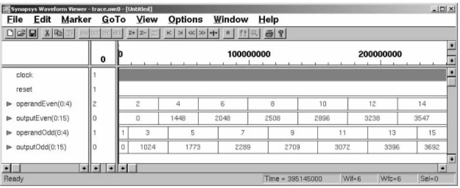
The waveform of a simulation run of the described system is given in Figure 2.12. The waveform, spanning approximately 300µs at a 33MHz clock, shows the inputs for which the square roots are computed (operandEven, operandOdd) as well as the results (outputEven, outputOdd). For the illustrated simulation run a precision of 6 bits for the integer places and 10 bits for the decimal places was chosen for the results. Intermediate computations use also higher precision. Note, that the results are represented as integer numbers by the waveform viewer. That means, for instance, that
sqrt(2) = 144810= 00000101101010002
gives the correct result after putting the binary point into the right place: 000001.01101010002= 1.414062510.
7
W Lis short for WordLength, andIW Lfor Integer WordLength. The number of bits right to the binary point is equal toW L−IW L.
Figure 2.12.: Simulation run for shared ALU.
2.6. Related Work
There is only very few work directly related to the matter of subject of this thesis. To the best of our knowledge, there does, at present date, no other work on the hardware synthesis of shared objects, or monitor-like concepts, exist apart from the one this thesis is based upon, and, in particular, no work on the optimising hardware synthesis of shared objects.
Nevertheless, we will in the following have a brief look at some pro-gramming languages and hardware description languages, which deal with related topics in a wider sense; synchronisation, concurrent object-oriented and distributed programming (a good overview can be found in [30]), and/or object-oriented hardware design. This overview will first of all allow us to dissociate our own work from existing work, but, in addition, some of the presented works also bear some ideas which are interesting in the context of this work, too.
2.6.1. Hardware
SUAVE
SUAVE (SAVANT and University of Adelaide VHDL Extension) [11,6,
10] is an extension of VHDL similar to Objective VHDL. Like Objective VHDL, SUAVE extends VHDL by a set of object-oriented features being
2.6. Related Work based on Ada95. These features include abstract data types, tagged types, inheritance, extended genericity, polymorphism, and, as abstract communication mechanism, channels and message passing [9, 8].
A channel is, in principle, simply a FIFO buffer to which messages can be stored in a first come first serve manner, and to which processes can access by a send, a receive, and a select primitive. Channels can be bounded or unbounded. A process trying to send a message to a channel is blocked, if the channel is completely filled with messages, so is a processes trying to receive a message from an empty channel. Unbounded channels will never cause the blocking of a sending process. A channel of length zero enforces a synchronous communication, that is, sender and receiver must meet to exchange a message.
Channels implement broadcasting, which means that all processes try-ing to receive a message from the same channel will consume the same message from that channel. A message is simply a typed object, and channels can only store messages of a certain type. Since SUAVE pro-vides for modelling of abstract data types, a channel can also commu-nicate messages of complex type. The select primitive provides for a nondeterministic choice between different possible actions on different channels.
SUAVE’s channels raise indeed the modelling of communication and synchronisation between processes to a more abstract level. A message queue that is associated with each channel as well as all operations on a channel are automatically managed by the language. But SUAVE’s ap-proach towards interprocess communication is based on message passing, and, thus, different from shared objects which are based on monitors. Moreover, SUAVE’s most serious drawback is the lack of an appropriate synthesis semantics, specifically, for channels. It is quite unclear, how a nondeterministic choice as provided by its select primitive, and un-bounded message queues should be implemented in hardware. However, we will later pick up the idea of asynchronous interprocess communica-tion in order to optimise the communicacommunica-tion between clients and shared objects.
Shared Variables in VHDL
VHDL [7, 57] provides for the possibility to declare shared variables, as subtypes of variables. Shared variables may appear within entity
declarations, architecture bodies, packages, package bodies, and blocks, where they might be used by concurrent processes. Since the 2000 edition of VHDL [55] a shared object is required to be of protected type.
A protected type in VHDL is quite similar to a protected type in Ada95, which is not surprising, after all, since VHDL and Ada share the same roots. A protected type definition consists of a protected type declaration, and a protected type body. The protected type declaration consists of a set of method declarations specifying the interface of the protected type. The body contains the implementation details of the protected type. Only the items in the declaration are visible to the outside. The language implementation enforces mutual exclusive access to the methods in the interface of a protected type. If methods are concurrently invoked, only one process will be granted access to the body of a method, and all other processes will be delayed. When the method execution has finished, one of the delayed processes may resume. The order in which processes are chosen for resumption is not defined.
Shared variables of protected type are quite similar to our understand-ing of shared objects, but a synthesis semantics has not yet been pre-sented for them. Consequently, existing synthesis tools do not support the synthesis of shared variables, at least not concurrently used shared variables. Therefore, the main problem discussed in this thesis, that is the synchronisation overhead caused to concurrently accessing processes, has not yet been addressed for shared variables.
SystemVerilog
SystemVerilog [1,94] is an extension to Verilog [56,14] proposed by Ac-cellera, an electronics industry organisation focused on electronic design automation (EDA). SystemVerilog addresses higher levels of abstraction for modelling and verification. It extends Verilog by a variety of features, such as assertions, interprocess communication and synchronisation, ex-tended operators, and new or exex-tended data types, including classes, many of them being adopted from C and C++. The extensions primar-ily aim at improving Verilog’s verification and testing abilities, as well as extending Verilog towards system level design. From our point of view basically classes, interfaces, and interprocess communication synchroni-sation are of interest.
2.6. Related Work that items, and can be used to create user-defined data types. But the SystemVerilog Language Reference Manual does not address the possi-bility of concurrently used objects.
An interface, like an entity in VHDL, comprises a set of nets and vari-ables, but in addition to VHDL’s entities, SystemVerilog’s interfaces can also contain declarations and definitions of functions and tasks which operate on those items. An interface can therefore also include function-ality, such as a communication protocol, which can be easily invoked by any process by specifying the name of an interface, and the method/task to be invoked. However, methods thus invoked can be regarded to be inlined at the invocation point, and, thus, are not remotely executed. Interfaces do, in particular, not provide any synchronisation mechanism, such that the avoidance of conflicts remains a handcrafted task.
For that purpose, one may fall back upon semaphores or mailboxes, two synchronisation primitives belonging to the SystemVerilog exten-sions. Semaphores in SystemVerilog have the usual meaning, and mail-boxes are quite similar to SUAVE’s channels, which means a mailbox basically represents a message queue, to which messages can be put, and from which messages can be taken. In addition, SystemVerilog also extends the expressive power of Verilog’s event-based synchronisation, such that more complex synchronisation schemes can be expressed in a more comfortable way.
As mentioned in the introduction, the SystemVerilog extensions do primarily focus on modelling and verification. Synthesis was not yet a basic concern, at least not for the newly introduced high level features, such as the synchronisation primitives. SystemVerilog has not yet been standardised, and synthesis tools able to process it are not yet available. It remains to bee seen, which, if any, of the advanced features will be finally supported for synthesis.
OOAS
Within the DFG (Deutsche Forschungsgemeinschaft) funded project OASE [78] at the University of Tuebingen technologies and methodolo-gies to support object-oriented modelling and verification, and partition-ing and synthesis of object-oriented hardware and mixed hardware/soft-ware specifications [90] were researched. In the course of this work, also a tool, called OOAS (object-oriented analysis and synthesis), was
devel-oped, which is able to process SystemC/C++ specifications including object-oriented features.
In the Tuebingen approach, classes, or, more precisely, objects, are interpreted as structural components, similar to SystemC’s modules, but with a method based interface instead of ports. However, according to the available publications [96,89,63,64], the approach does not seem to address concurrent access to such objects, and, consequently, does not deal with synchronisation issues. We must therefore conclude that OOAS is only able to process specification including objects, whose methods are not concurrently invoked, which is in contrast to the shared objects as considered in this work.
2.6.2. Concurrent Programming (Software)
The goal of performance optimisation for