University of Windsor University of Windsor
Scholarship at UWindsor
Scholarship at UWindsor
Electronic Theses and Dissertations Theses, Dissertations, and Major Papers
2011
Structural Behaviour of Dented Pipelines
Structural Behaviour of Dented Pipelines
Abu Naim Md Rafi
University of Windsor
Follow this and additional works at: https://scholar.uwindsor.ca/etd
Recommended Citation Recommended Citation
Rafi, Abu Naim Md, "Structural Behaviour of Dented Pipelines" (2011). Electronic Theses and Dissertations. 89.
https://scholar.uwindsor.ca/etd/89
This online database contains the full-text of PhD dissertations and Masters’ theses of University of Windsor students from 1954 forward. These documents are made available for personal study and research purposes only, in accordance with the Canadian Copyright Act and the Creative Commons license—CC BY-NC-ND (Attribution, Non-Commercial, No Derivative Works). Under this license, works must always be attributed to the copyright holder (original author), cannot be used for any commercial purposes, and may not be altered. Any other use would require the permission of the copyright holder. Students may inquire about withdrawing their dissertation and/or thesis from this database. For additional inquiries, please contact the repository administrator via email
Structural Behaviour of Dented Pipelines
By
Abu Naim Md Rafi
A Thesis
Submitted to the Faculty of Graduate Studies through Civil and Environmental Engineering in Partial Fulfillment of the Requirements for the Degree of Master of Applied Science at the
University of Windsor
Windsor, Ontario, Canada
2011
Structural Behaviour of Dented Pipelines
By
Abu Naim Md Rafi
APPROVED BY:
______________________________________________ Dr Randy Bowers, Outside Department Reader
Department of Mechanical, Automotive and Materials Engineering
______________________________________________ Dr. Shaohong Cheng, Department Reader
Department of Civil and Environmental Engineering
___________________________________________ Dr. Sreekanta Das, Advisor
Department of Civil and Environmental Engineering
______________________________________________ Dr. Hanna Maoh, Chair of Defense
Department of Civil and Environmental Engineering
DECLARATION OF ORIGINALITY
I hereby certify that I am the sole author of this thesis and that no part of this thesis has
been published or submitted for publication.
I certify that, to the best of my knowledge, my thesis does not infringe upon anyone’s
copyright nor violate any proprietary rights and that any ideas, techniques, quotations, or
any other material from the work of other people included in my thesis, published or
otherwise, are fully acknowledged in accordance with the standard referencing practices.
Furthermore, to the extent that I have included copyrighted material that surpasses the
bounds of fair dealing within the meaning of the Canada Copyright Act, I certify that I
have obtained a written permission from the copyright owner(s) to include such
material(s) in my thesis and have included copies of such copyright clearances to my
appendix.
I declare that this is a true copy of my thesis, including any final revisions, as approved
by my thesis committee and the Graduate Studies office, and that this thesis has not been
iv ABSTRACT
A dent is a defect in the pipe wall in the form of localized inward plastic deformation.
Dents are a matter of serious concern for pipeline operators because they may cause a
rupture or a leak in the pipeline. Hence, a reliable strain-based criterion for the
assessment of dents is very important. An understanding of the local strain distributions
in the dent is very important for the development of a strain-based dent evaluation
criterion. Therefore, this study was undertaken using full-scale tests and a parametric
study to assess the influence of various parameters on the strain distributions in a dent.
Additionally, the ASME strain-based dent evaluation criterion was reviewed.
It was shown that strain distributions and strain values in a dent are significantly
influenced by the dent depth, internal pressure, and dent shape. The study also noted that
DEDICATION
ACKNOWLEDGEMENTS
I am deeply grateful to my supervisor Dr. Sreekanta Das whose help, inspiring
suggestions, continuous support and encouragement helped me in all the time of this
research work and writing of this thesis. Dr. Das devoted his time and sincere effort to
provide all necessary research facilities for this work. I would like to express my
appreciation to the committee members: Dr. R Bowers and Dr. S Cheng for their valuable
and constructive suggestions. I would also like to express my gratitude to Jeorge, Sara
and Hanif for their sincere help.
The assistance of Mr. M. St. Louis, Mr. L. Pop and Mr. P. Seguin in the laboratory works
is sincerely acknowledged.
Finally I would like to thank my family members for their love, encouragement and
support.
TABLE OF CONTENTS
DECLARATION OF ORIGINALITY ... iii
ABSTRACT ... iv
DEDICATION ...v
ACKNOWLEDGEMENTS ... vi
LIST OF TABLES ... xi
LIST OF FIGURES ... xiii
CHAPTER 1. INTRODUCTION 1.1 General ...1
1.2 Statement of the Problem ...3
1.3 Objectives ...4
1.4 Organization of the Thesis ...5
2. REVIEW OF LITERATURE 2.1 General ...6
2.2 Dent ...6
2.3 Recommendations in Codes and Manuals ...8
2.3.1 Depth Based Criteria ...8
2.3.1.1 ASME B31.4 ...9
2.3.1.2 ASME B31.8 ...9
2.3.1.3 DNV-OS-F101 ...10
2.3.1.4 CSA Z662-07 ...11
2.3.1.5 EPRG Methods ...11
2.3.1.6 PDAM ...13
2.3.2 Strain Based Criteria ...14
2.4 Burst Strength of Pipe with Dent ...16
2.4.1 Burst Strength of Pipe with Plain-Smooth Dent ...16
2.4.2 Burst Strength of Pipe with Plain-Kinked Dent ...17
2.5 Fatigue Life of Pipe with Dent ...17
2.7 Conclusions ...28
3. EXPERIMENTAL PROGRAM 3.1General ...35
3.2 Selection of Specimen Parameters ...36
3.3 Preparation of the specimen ...36
3.4 Selection of Boundary Conditions ...37
3.5 Selection of Indenter Shape ...37
3.6 Internal pressure ...38
3.7 Test Variables ...39
3.8 Designation of Specimen ...40
3.9 Material Property ...40
3.10 Experimental Setup ...41
3.10.1 Loading Jack and Loadcell ...41
3.10.2 Fluid Pump and Pressure Transducer ...42
3.10.3 Linear Voltage Displacement Transducers ...42
3.10.4 Electronic Resistance Strain Gauges. ...42
3.10.5 Data Acquisition System ...43
3.11 Test Procedure ...43
3.11.1 Test 1: Specimen LRP20D4 ...44
3.11.2 Test 2: Specimen LRP40D4 ...44
3.11.3 Test 3: Specimen SSP20D8 ...45
3.11.4 Tests 4 to 6: Specimen SRP20D10, SRP20D8 and SRP20D12 ...45
3.11.5 Tests 7 to 9: Specimen SDP0D8, SDP20D8 and SDP40D8 ...47
4. TEST RESULTS 4.1 General ...67
4.2 Load-deformation Behaviour ...67
4.2.1 Effect of Internal Pressure ...68
4.2.2 Effect of Indenter Shape ...69
4.3 Deformed Shapes and Strain Distributions ...70
4.3.1 Specimen LRP20D4 ...70
4.3.2 Specimen LRP40D4 ...71
4.3.3 Specimen SSP20D8 ...72
4.3.4 Specimen SRP20D10 ...74
4.3.5 Specimen SRP20D8 ...75
4.3.6 Specimen SRP20D12 ...76
4.3.7 Specimen SDP0D8 ...77
4.3.9 Specimen SDP40D8 ...79
4.4 Effect of Different Parameters on Strain Distributions ...80
4.4.1 Effect of Internal Pressure ...80
4.4.2 Effect of Dent Shape ...82
4.4.3 Effect of Dent Depth ...82
4.5 Conclusions ...84
5. DEVELOPMENT OF FINITE ELEMENT MODEL 5.1 General ...126
5.2 Finite Element Model ...127
5.2.1 Element Selection ...127
5.2.2 Symmetry of the Model ...128
5.2.3 End Caps ...129
5.2.4 Support Conditions ...130
5.2.5 Indenter ...132
5.2.6 Material Model ...132
5.2.7 Loading Procedure ...133
5.2.8 Mesh Study ...135
5.2.9 Contact Algorithm ...138
5.2.10 Solution Methods and Convergence ...142
6. VALIDATION OF FINITE ELEMENT MODEL AND PARAMETRIC STUDY 6.1 General ...165
6.2 Comparison of the FEA and Experimental results ...165
6.2.1 Specimen LRP20D4 and LRP40D4 ...166
6.2.2 Specimen SSP20D8 ...167
6.2.3 Specimen SRP20D8, SRP20D10, and SRP20D12 ...168
6.3 Parametric Study ...169
6.3.1 Effect of Dent Depth ...170
6.3.1.1 Spherical Dent ...170
6.3.1.2 Rectangular Dent ...171
6.3.2 Effect of Internal Pressure ...172
6.3.3 Effect of Indenter Shape ...173
6.4 Conclusions ...173
7.4 Finite Element Analysis ...221
7.5. Review of ASME B31.8 Equations and Assumptions ...222
7.5.1 Membrane Strain in Circumferential Direction ...222
7.5.2 Membrane Strain in Longitudinal Direction ...226
7.5.3 Review of the ASME Equations for Calculating Effective Strain ...227
7.5.4 Incorporation of Circumferential Membrane Strain ...229
7.5.5 Comparison between the Effective Strains Calculated Using Different Equations...229
7.6 Conclusions ...230
8. SUMMARY, CONCLUSIONS AND RECOMMENDATIONS 8.1 General ...249
8.2 Summary ...249
8.3 Conclusions ...250
8.4 Recommendations ...252
REFERENCES ...253
APPENDIX ...258
LIST OF TABLES
Table 2.1: Details of the indenter used by Keating and Hoffman (1997)... 30
Table 3.1: Test Matrix... 48
Table 3.2: Material Properties... 49
Table 4.1: Effect of internal pressure on the maximum strain values... 86
Table 4.2: Effect of indenter shape on the maximum strain values... 87
Table 4.3: Effect of dent depth for rectangular indenter... 88
Table 4.4: Effect of dent depth for spherical indenter... 89
Table 4.5: Effect of dent depth for dome indenter... 90
Table 5.1: Mesh Study... 145
Table 6.1: Maximum circumferential strain values... 176
Table 6.2: Maximum longitudinal strain values... 178
Table 7.1: Parameters Used for FEA Analysis... 232
Table 7.2: Maximum circumferential tensile membrane strain obtained from the FEA Model... 233
Table 7.4: Effect of pressure on the circumferential membrane strain... 235
Table 7.5: Effect of pressure on the longitudinal membrane strain... 236
Table 7.6: Maximum strain components in dent... 237
LIST OF FIGURES
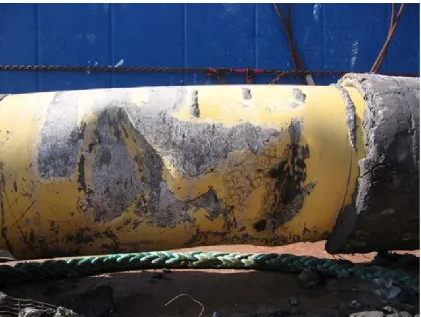
Figure 2.1: Photograph of a dent in the pipe wall (Source:http://www.google.ca/images)
... 31
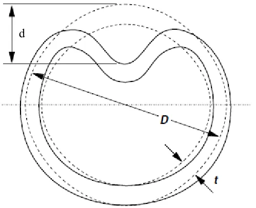
Figure 2.2: Dimensions of a dent (Macdonald et al. 2006) ... 31
Figure 2.3: Photograph of kinked dent in field pipeline (Macdonald et.al. 2006) ... 32
Figure 2.4: Photograph of a dent-crack defect (Source:http://www.easervices.com) ... 32
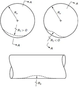
Figure 2.5: Geometric parameter of a dent (ASME B31.8-2007) ... 33
Figure 2.6: Flank of a dent ... 33
Figure 2.7: Definition of dent length (Noronha et al. 2010) ... 34
Figure 3.1: Photograph of a large pipe specimen ... 50
Figure 3.2: Photograp of small pipe specimen ... 51
Figure 3.3 Photographs of the indenters ... 52
Figure 3.4: Schematic of the indenters ... 53
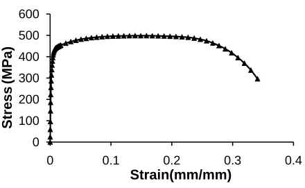
Figure 3.5: Tensiel stress-strain behavior of coupon from large diameter pipe ... 54
Figure 3.6: Tensile stress-strain behavior of coupon from small diameter pipe. ... 55
Figure 3.7: Schematic of the experimental setup ... 56
Figure 3.8: Photograph of the experimental setup ... 57
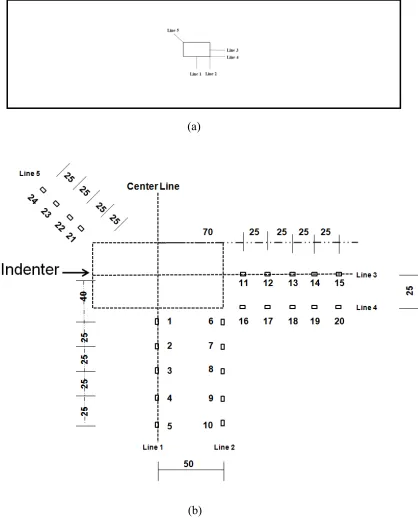
Figure 3.9: Strain gauge layout pattern for specimen LRP20D4 and LRP40D4 ... 58
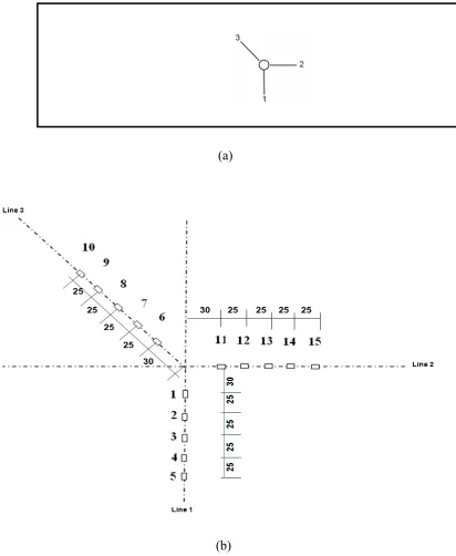
Figure 3.10: Strain gauge layout pattern for specimen SRP20D8, SRP20D10 and SRP20D12... 59
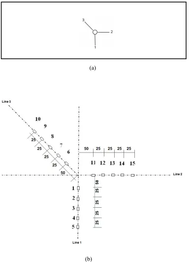
Figure 3.11: Strain gauge layout pattern for specimen SSP20D8 ... 60
Figure 3.13: Load-deformation behavior of specimen LRP20D4 ... 62
Figure 3.14: Load-deformation behavior of specimen LRP40D4 ... 62
Figure 3.15: Load-deformation behavior of specimen SSP20D8 ... 63
Figure 3.16: Load-deformation behavior of specimen SRP20D10 ... 63
Figure 3.17: Load-deformation behavior of specimen SRP20D8 ... 64
Figure 3.18: Load-deformation behavior of specimen SRP20D12 ... 64
Figure 3.19: Load-deformation behavior of specimen SDP0D8 ... 65
Figure 3.20: Load-deformation behavior of specimen SDP20D8 ... 65
Figure 3.21: Load-deformation behavior of specimen SDP40D8 ... 66
Figure 4.1: Effect of internal pressure on the load deformation behavior for a rectangular indenter. ... 91
Figure 4.2: Effect of internal pressure on the load deformation behavior for a dome indenter ... 91
Figure 4.3: Effect of indenter shape on the lod deformation behavior ... 92
Figure 4.4: Photograph of the dent in specimen LRP20D4 ... 92
Figure 4.5(a): Circumferential strain distribution along Line 1 for specimen LRP20D4 . 93 Figure 4.5(b): Circumferential strain distribution along Line 2 for specimen LRP20D4 93 Figure 4.6(a): Longitudinal strain distribution along Line 3 for specimen LRP20D4 ... 94
Figure 4.6(b): Longitudinal strain distribution along Line 4 for specimen LRP20D4 ... 94
Figure 4.7: Strain distributiona along the Line 5 for specimen LRP20D4 ... 95
Figure 4.8: Photograph of the dent in specimen LRP40D4 ... 95
Figure 4.9(a): Circumferential strain distribution along Line 1 for specimen LRP40D4 . 96
Figure 4.10(a): Longitudinal strain distribution along Line 3 for specimen LRP40D4 ... 97
Figure 4.10(b): Longitudinal strain distribution along Line 4 for specimen LRP40D4 ... 97
Figure 4.11: Strain distributiona along the Line 5 for specimen LRP40D4 ... 98
Figure 4.12: Photograph of the dent in specimen SSP20D8 ... 98
Figure 4.13: Circumferential strain distribution for specimen SSP20D8 ... 99
Figure 4.14: Longitudinal strain distribution for specimen SSP20D8 ... 99
Figure 4.15: Oblique strain distribution for specimen SSP20D8 ... 100
Figure 4.16: Photograph of the dent in specimen SRP20D10 ... 100
Figure 4.17(a): Circumferential strain distribution along Line 1 for specimen SRP20D10 ... 101
Figure 4.17(b): Circumferential strain distribution along Line 2 for specimen SRP20D10 ... 101
Figure 4.18(a): Longitudinal strain distribution along Line 3 for specimen SRP20D10 102 Figure 4.18(b): Longitudinal strain distribution along Line 4 for specimen SRP20D10 102 Figure 4.19: Strain distributiona along the Line 5 for specimen SRP20D10 ... 103
Figure 4.20: Photograph of the dent in specimen SRP20D8 ... 103
Figure 4.21(a): Circumferential strain distribution along Line 1 for specimen SRP20D8 ... 104
Figure 4.21(b): Circumferential strain distribution along Line 2 for specimen SRP20D8 ... 104
Figure 4.22(a): Longitudinal strain distribution along Line 3 for specimen SRP20D8 .. 105
Figure 4.24(a): Circumferential strain distribution along Line 1 for specimen SRP20D12
... 106
Figure 4.24(b): Circumferential strain distribution along Line 2 for specimen SRP20D12 ... 107
Figure 4.25(a): Longitudinal strain distribution along Line 3 for specimen SRP20D12 107 Figure 4.25(b): Longitudinal strain distribution along Line 4 for specimen SRP20D12 108 Figure 4.26: Photograph of the dent in specimen SDP0D8 ... 108
Figure 4.27: Circumferential strain distribution for specimen SDP0D8 ... 109
Figure 4.28: Longitudinal strain distribution for specimen SDP0D8 ... 109
Figure 4.29: Oblique strain distribution for specimen SDP0D8 ... 110
Figure 4.30: Photograph of the dent in specimen SDP20D8 ... 110
Figure 4.31: Circumferential strain distribution for specimen SDP20D8 ... 111
Figure 4.32: Longitudinal strain distribution for specimen SDP20D8 ... 111
Figure 4.33: Oblique strain distribution for specimen SDP20D8 ... 112
Figure 4.34: Photograph of the dent in specimen SDP40D8 ... 112
Figure 4.35: Circumferential strain distribution for specimen SDP40D8 ... 113
Figure 4.36: Longitudinal strain distribution for specimen SDP40D8 ... 113
Figure 4.37: Oblique strain distribution for specimen SDP40D8 ... 114
Figure 4.38(a): Effect of internal pressure on the circumferential strain distribution for rectangular indenter along Line 1 ... 114
Figure 4.38(c): Effect of internal pressure on the longitudinal strain distribution for
rectangular indenter along Line 3 ... 115
Figure 4.38(d): Effect of internal pressure on the longitudinal strain distribution for
rectangular indenter along Line 4 ... 116
Figure 4.38(e): Effect of internal pressure on the oblique strain distribution for
rectangular indenter along Line 5 ... 116
Figure 4.39(a): Effect of internal pressure on the circumferential strain distribution for
dome indenter along Line 1 ... 117
Figure 4.39(b): Effect of internal pressure on the longitudinal strain distribution for dome
indenter along Line 2 ... 117
Figure 4.39(c): Effect of internal pressure on the oblique strain distribution for dome
indenter along Line 3 ... 118
Figure 4.40(a): Effect of dent shape on circumferential strain distribution ... 118
Figure 4.40(b): Effect of dent shape on longitudinal strain distribution ... 119
Figure 4.41(a): Effect of dent depth on circumferential strain distribution along Line 1119
Figure 4.41(b): Effect of dent depth on circumferential strain distribution along Line 2
... 120
Figure 4.41(c): Effect of dent depth on longitudinal strain distribution along Line 3 .... 120
Figure 4.41(d): Effect of dent depth on longitudinal strain distribution along Line 4 .... 121
Figure 4.42(a): Effect of dent depth on the maximum circumferential strain for
rectangular indenter ... 121
Figure 4.42(c): Effect of dent depth on the maximum circumferential strain for spherical
indenter ... 122
Figure 4.42(d): Effect of dent depth on the maximum longitudinal strain for spherical indenter ... 123
Figure 4.42(e): Effect of dent depth on the maximum oblique strain for spherical indenter ... 123
Figure 4.42(f): Effect of dent depth on the maximum circumferential strain for dome indenter ... 124
Figure 4.42(g): Effect of dent depth on the maximum longitudinal strain for dome indenter ... 124
Figure 4.42(h): Effect of dent depth on the maximum oblique strain for dome indenter 125 Figure 5.1 Half symmetry in the FEA model ... 146
Figure 5.2: Comparison between Load-deformation behaviour of full-pipe model and half symmetric model ... 147
Figure 5.3: Comparison between circumferential strain distribution of full-pipe model and half-symmetric model ... 148
Figure 5.4: Types of end caps used in FE model ... 149
Figure 5.5: Effect of shapes of end caps on load-deformation behavior ... 150
Figure 5.6: Cross section of pipe end showing 18o roller or pin support ... 151
Figure 5.7: Effect of various boundary conditions at mid-span support ... 152
Figure 5.8: Effect of end-span support condition ... 153
Figure 5.9: True stress-strain behavior of 762 mm pipe material ... 154
Figure 5.11: Effect of mesh refinement in longitudinal direction on the load-deformation
behavior... 156
Figure 5.12: Effect of mesh refinement in longitudinal direction on the longitudinal strain distribution along the longitudinal center line ... 157
Figure 5.13: Effect of local mesh refinement on load –deformation behavior ... 158
Figure 5.14: Effect of local mesh refinement on strain distribution along longitudinal centerline ... 159
Figure 5.15: Effect of circumferential mesh refinement on the load-deformation behavior ... 160
Figure 5.16: Effect of circumferential mesh refinement on the strain distribution along circumferential centerline ... 161
Figure 5.17: Mesh configuration for large pipe model ... 162
Figure 5.18: Mesh configuration for half small pipe model ... 163
Figure 5.19: Mesh configuration for small pipe model ... 164
Figure 6.1: Experimental and numerical load-deformation behaviors of Specimen LRP20D4 ... 180
Figure 6.2(a): Experimental and numerical circumferential strain distributions for Specimen LRP20D4 for Line 1 ... 181
Figure 6.2(b): Experimental and numerical circumferential strain distributions for Specimen LRP20D4 for Line 2 ... 181
Figure 6.3(b): Experimental and numerical longitudinal strain distributions for Specimen
LRP20D4 for Line ... 182
Figure 6.4: Experimental and numerical load-deformation behaviors of Specimen
LRP40D4 ... 183
Figure 6.5(a): Experimental and numerical circumferential strain distributions for
Specimen LRP40D4 for Line 1 ... 184
Figure 6.5(b): Experimental and numerical circumferential strain distributions for
Specimen LRP40D4 for Line 2 ... 184
Figure 6.6(a): Experimental and numerical longitudinal strain distributions for Specimen
LRP40D4 for Line 3 ... 185
Figure 6.6(b): Experimental and numerical longitudinal strain distributions for Specimen
LRP40D4 for Line 4 ... 185
Figure 6.7: Experimental and numerical load-deformation behaviors of Specimen
SSP20D8 ... 186
Figure 6.8: Experimental and numerical circumferential strain distributions for Specimen
SSP20D8 ... 187
Figure 6.9: Experimental and numerical longitidinal strain distributions for Specimen
SSP20D8 ... 188
Figure 6.10: Experimental and numerical load-deformation behaviors of Specimen
SRP20D8... 189
Figure 6.11(a): Experimental and numerical circumferential strain distributions for
Figure 6.11(b): Experimental and numerical circumferential strain distributions for
Specimen SRP20D8 for Line 2 ... 190
Figure 6.12(a): Experimental and numerical longitudinal strain distributions for Specimen
SRP20D8 for Line 3... 191
Figure 6.12(b): Experimental and numerical longitudinal strain distributions for
Specimen SRP20D8 for Line 4 ... 191
Figure 6.13: Experimental and numerical load-deformation behaviors of Specimen
SRP20D10... 192
Figure 6.14(a): Experimental and numerical circumferential strain distributions for
Specimen SRP20D10 for Line 1 ... 193
Figure 6.14(b): Experimental and numerical circumferential strain distributions for
Specimen SRP20D10 along Line 2 ... 193
Figure 6.15(a): Experimental and numerical longitudinal strain distributions for Specimen
SRP20D10 for Line 3... 194
Figure 6.15(b): Experimental and numerical longitudinal strain distributions for
Specimen SRP20D10 for Line 4 ... 194
Figure 6.16: Experimental and numerical load-deformation behaviors of Specimen
SRP20D12... 195
Figure 6.17(a): Experimental and numerical circumferential strain distributions for
Specimen SRP20D12 for Line 1 ... 196
Figure 6.17(b): Experimental and numerical circumferential strain distributions for
Figure 6.18(a): Experimental and numerical longitudinal strain distributions for Specimen
SRP20D12 for Line 3... 197
Figure 6.18(b): Experimental and numerical longitudinal strain distributions for
Specimen SRP20D12 for Line 4 ... 197
Figure 6.19(a): Effect of dent depth on the maximum circumferential tensile strain for
spherical indenter and pipe with D/t of 34 ... 198
Figure 6.19(b): Effect of dent depth on the maximum circumferential compressive strain
for spherical indenter and pipe with D/t of 34 ... 198
Figure 6.19(c): Effect of dent depth on the maximum longitudinal tensile strain for
spherical indenter and pipe with D/t of 34 ... 199
Figure 6.19(d): Effect of dent depth on the maximum longitudinal compressive strain for
spherical indenter and pipe with D/t of 34 ... 199
Figure 6.19(e): Effect of dent depth on the maximum circumferential tensile strain for
spherical indenter and pipe with D/t of 70 ... 200
Figure 6.19(f): Effect of dent depth on the maximum circumferential compressive strain
for spherical indenter and pipe with D/t of 70 ... 200
Figure 6.19(g): Effect of dent depth on the maximum longitudinal tensile strain for
spherical indenter and pipe with D/t of 70 ... 201
Figure 6.19(h): Effect of dent depth on the maximum longitudinal compressive strain for
spherical indenter and pipe with D/t of 70 ... 201
Figure 6.19(i): Effect of dent depth on the maximum circumferential tensile strain for
Figure 6.19(j): Effect of dent depth on the maximum circumferential compressive strain
for rectangular indenter and pipe with D/t of 34 ... 202
Figure 6.19(k): Effect of dent depth on the maximum longitudinal tensile strain for
rectangular indenter and pipe with D/t of 34 ... 203
Figure 6.19(l): Effect of dent depth on the maximum longitudinal compressive strain for
rectangular indenter and pipe with D/t of 34 ... 203
Figure 6.20(a): Effect of internal pressure on the maximum circumferential tensile strain
for spherical indenter and pipe with D/t of 34 ... 204
Figure 6.20(b): Effect of internal pressure on the maximum circumferential compressive
strain for spherical indenter and pipe with D/t of 34 ... 204
Figure 6.20(c): Effect of internal pressure on the maximum longitudinal tensile strain for
spherical indenter and pipe with D/t of 34 ... 205
Figure 6.20(d): Effect of internal pressure on the maximum longitudinal compressive
strain for spherical indenter and pipe with D/t of 34 ... 205
Figure 6.20(e): Effect of internal pressure on the maximum circumferential tensile strain
for spherical indenter and pipe with D/t of 70 ... 206
Figure 6.20(f): Effect of internal pressure on the maximum circumferential compressive
strain for spherical indenter and pipe with D/t of 70 ... 206
Figure 6.20(g): Effect of internal pressure on the maximum longitudinal tensile strain for
spherical indenter and pipe with D/t of 70 ... 207
Figure 6.20(h): Effect of internal pressure on the maximum longitudinal compressive
Figure 6.20(i): Effect of internal pressure on the maximum circumferential tensile strain
for rectangular indenter and pipe with D/t of 34 ... 208
Figure 6.20(j): Effect of internal pressure on the maximum circumferential compressive
strain for rectangular indenter and pipe with D/t of 34 ... 208
Figure 6.20(k): Effect of internal pressure on the maximum longitudinal tensile strain for
rectangular indenter and pipe with D/t of 34 ... 209
Figure 6.20(l): Effect of internal pressure on the maximum longitudinalcompressive
strain for rectangular indenter and pipe with D/t of 34 ... 209
Figure 6.21(a): Effect of indenter shape on the maximum circumferential tensile strain at
0 internal pressure and pipe with D/t of 34 ... 210
Figure 6.21(b): Effect of indenter shape on the maximum circumferential compressive
strain at 0 internal pressure and pipe with D/t of 34 ... 210
Figure 6.21(c): Effect of indenter shape on the maximum longitudinal tensile strain at 0
internal pressure and pipe with D/t of 34 ... 211
Figure 6.21(d): Effect of indenter shape on the maximum longitudinal compressive strain
at 0 internal pressure and pipe with D/t of 34 ... 211
Figure 6.21(e): Effect of indenter shape on the maximum circumferential tensile strain at
0 internal pressure and pipe with D/t of 34 ... 212
Figure 6.21(f): Effect of indenter shape on the maximum circumferential compressive
strain at 0.25py internal pressure and pipe with D/t of 34 ... 212
Figure 6.21(g): Effect of indenter shape on the maximum longitudinal tensile strain at
Figure 6.21(h): Effect of indenter shape on the maximum longitudinal compressive strain
at 0.25py internal pressure and pipe with D/t of 34 ... 213
Figure 6.21(i): Effect of indenter shape on the maximum circumferential tensile strain at
0.45py internal pressure and pipe with D/t of 34 ... 214
Figure 6.21(j): Effect of indenter shape on the maximum circumferential compressive
strain at 0.45py internal pressure and pipe with D/t of 34 ... 214
Figure 6.21(k): Effect of indenter shape on the maximum longitudinal tensile strain at
0.45 py internal pressure and pipe with D/t of 34 ... 215
Figure 6.21(l): Effect of indenter shape on the maximum longitudinalcompressive strain
at 0.45 py internal pressure and pipe with D/t of 34 ... 215
Figure 6.21(m): Effect of indenter shape on the maximum circumferential tensile strain at
0.65py internal pressure and pipe with D/t of 34 ... 216
Figure 6.21(n): Effect of indenter shape on the maximum circumferential compressive
strain at 0.65py internal pressure and pipe with D/t of 34 ... 216
Figure 6.21(0): Effect of indenter shape on the maximum longitudinal tensile strain at
0.65 py internal pressure and pipe with D/t of 34 ... 217
Figure 6.21(p): Effect of indenter shape on the maximum longitudinalcompressive strain
at 0.65 py internal pressure and pipe with D/t of 34 ... 217
Figure 7.1: Geometric parameter of a dent (ASME B31.8-2007) ... 239
Figure 7.2(a): Photograph of a dent created by a spherical indenter ... 240
Figure 7.2 (b): FEA simulation of a spherical dent. ... 240
Figure 7.3(b). FEA simulation of a rectangular dent ... 241
Figure 7.3: Experimental and FEA dent shapes simulated by rectangular indenter ... 241
Figure 7.4 (a): Effect of dent depth on circumferential membrane strain for rectangular
indenter ... 242
Figure 7.4 (b): Effect of internal pressure on circumferential membrane strain for
rectangular indenter ... 242
Figure 7.5 (a): Effect of dent depth on circumferential membrane strain for spherical
indenter ... 243
Figure 7.5 (b): Effect of internal pressure on circumferential membrane strain for
spherical indenter ... 243
Figure 7.6: Effect of internal pressure on longitudinal membrane strain for rectangular
indenter ... 244
Figure 7.7: Effect of internal pressure on longitudinal membrane strain for spherical
indenter. ... 244
Figure 7.8: Effect of ciccumferentia membrane strain on the inner surface effective strain
calculation for dent created with rectangular indenter under different internal
pressure level ... 245
Figure 7.9: Effect of ciccumferentia membrane strain on the outer surface effective strain
calculation for dent created with rectangular indenter under different internal
pressure level ... 246
Figure 7.10: Effect of ciccumferentia membrane strain on the inner surface effective
strain calculation for dent created with spherical indenter under different internal
Figure 7.11: Effect of ciccumferentia membrane strain on the outer surface effective
strain calculation for dent created with spherical indenter under different internal
CHAPTER 1
INTRODUCTION
1.1 General
The energy related industries in North America use steel pipelines as the primary mode
for transporting natural gas, crude oil, and various petroleum products. In Canada alone,
about 700,000 km of energy pipelines are in operation. Many additional pipelines
projects especially in West Canada and Alaska of various scales such as Mackenzie Gas
Project and Alaska Highway Pipeline are underway. The Alaska Highway Pipeline
Project which will run between Prudhoe Bay in Alaska to various parts of USA through
Yukon, British Columbia, and Alberta will alone cost about US$ 20 billion (Yukon
Government, 2011). The majority of these pipelines run below ground. A significant
threat to the structural integrity of the buried pipeline is damage or defect resulting from
third party interference or backfill loads over hard spots underneath the pipeline. Defects
in the field pipeline can occur in the form of dent, corrosion, gouge, crack, and wrinkle.
A combination of two or more defects is also common in the field pipelines. These
defects may pose serious threats to the structural and/or operational integrity of the
pipeline. According to the Office of Pipeline Safety of US Department of Transportation,
28% of the pipeline accidents reported from 1985 to 2003 is caused by mechanical
damage (Kiefner et al. 2006).
A dent is an inward permanent plastic deformation of the pipe wall which causes a gross
distortion of the pipe cross section. A dent can form due to many reasons. Onshore
pipelines are often subjected to transverse load, often concentrated on a small area of pipe
the impact by excavation equipment. Often dent in the field pipeline forms because of the
fact that the line pipe is resting on a rock or hard surface for a considerable time period.
Dents in the pipeline can form alone or may be combined with additional surficial
damage such as cracks and gouges. Dents with additional damages are typically caused
by third party actions and result in immediate failure approximately 80% of the time
(Rosenfeld, 2002). On the other hand, dents without any other damages (plain dents)
may not be an immediate threat to the structural integrity of pipeline. However, a plain
dent is able to cause damages to the structural integrity in the long run due to fluctuations
of the operating pressure in the pipeline. Apart from this, dent alone can create other
damages due to the development of ancillary problems, such as coating damage,
corrosion, and stress-corrosion cracking (Baker, 2004).
A large number of studies by various research groups and individual researchers were
completed to study the effect of dent on the structural behavior of the pipe under
monotonically increasing quasi-static and cyclic pressure loadings. Cosham and Hopkins
(2003) reviewed the existing literature on burst strength of pipe with plain-smooth dent
(dent for which the change in curvature is smooth and free of other forms of defects). It
was found that from 1958 to 2000 about 75 burst tests were completed and only four
pipes failed in the dent. Hence, it was concluded that a plain-smooth dent does not
reduce the burst strength of pipe much unless the dent is very deep. There is no research
reported in the literature regarding the burst strength of pipe with plain-kinked dent (dent
for which the change in curvature is sharp and which is free of other forms of defects).
fatigue behavior of dented pipes under cyclic internal pressure was performed by Fowler
et al. (1995) and Keating and Hoffman (1997). These studies found that a dent in the
pipeline can fail due to fatigue loading. It was also found that fatigue life of a dent is
dependent on the depth, length, and width of the dent. Apart from depth and length of the
dent its sharpness (change in curvature at the dent) plays a very important role on the
fatigue life of the dent. For example, Cosham and Hopkins (2003), reported a significant
difference can be expected between the fatigue life of a plain-smooth and the fatigue life
of a plain-kinked dent.
1.2 Statement of the Problem
Dent is a common form of defect in field pipelines. It can pose serious threat to the
operational and/or structural integrity of these pipelines. Hence, a reliable criterion for the
accurate assessment of dent is very important. Dent depth as a percentage of outer
diameter of the pipe is the only parameter most commonly used by the different codes,
standards, and manuals for determining the severity and acceptability of a dent (for
example, ASME 2006; DNV, 2007; CSA, 2007; EPRG; and PDAM). However, dent
depth which is merely a geometric parameter, is not always the most useful parameter for
identifying whether or not a dent could be a threat to the structural integrity of a field
pipeline. Studies showed that other parameters such as length, width, and sharpness of
dent also play a significant role in the structural behavior of the dent. Therefore, a dent
depth-based criterion alone for the assessment of dent severity is not rational. Dent is a
defect in the form of permanent depth in the pipe wall, and hence, the local strains and
strain concentrations in the pipe wall material is a more appropriate criterion for judging
(2007)) acknowledges this concept and hence, offers an option for using strain-based
criterion for determining severity of dents. It also provides non-mandatory formulas for
calculating the total (critical) strains in a dent. However, the equations presented in this
code are not universally accepted and many researchers raised questions about the
assumptions and equations presented in the ASME B 31.8 code (2007). Hence, this study
performed a detailed review of the strain-based dent evaluation criterion recommended in
the ASME B31.8 code (2007) and provided recommendations for the improvement of
this criterion
Majority of the previous works on strain analysis of a dent were completed primarily to
determine the strain values and strain distributions in the dent when an already dented
pipe is being loaded with monotonically increasing pressure load. However, no
experimental and numerical studies to determine the strains in the dent as the dent being
formed are found in the literature. A few studies were presented analytical approaches for
the calculation of dent strains. However, these studies did not investigate the effect of
different parameters such as dent depth, dent shape, and internal pressure during
indentation on the strain distributions of the dent. Hence, this research undertook a
thorough study of the effect of different parameters on the stain distributions in a dent of
pipeline.
1.3 Objectives
Therefore, the current study was undertaken to understand the behavior of the pipeline
strain in the dent of oil and gas pipes. The following are the objectives of this research
project.
1. To study the overall structural behavior of the pipe while subjected to concentrated
lateral (denting) loading.
2. To investigate the effect of internal pressure during denting, dent depth, and dent
shapes on the strain values in a dent.
3. To review and revisit the ASME strain-based dent evaluation criterion and provide
recommendations for improvement of the criterion.
1.4 Organization of the Thesis
The thesis is divided into eight chapters. The first chapter is introduction and the very last
chapter, Chapter 8 is Summary, Conclusions and Recommendations. Chapter 2
summarizes the findings of the previous research works and the recommendations made
by various codes, standards, and manuals. Chapters 3 and 4 discuss the test program and
the results obtained from the full-scale tests. The development of the finite element (FE)
model is presented in chapter 5. Chapter 6 presents the validation of the FE model and
the results of the parametric study completed using the FE model. Review of the ASME
CHAPTER 2
REVIEW OF LITERATURE
2.1 General
A review of the literature was conducted to study how current guidelines and the previous
research works address the significance of dent in pipeline. It was found that the dent
depth as a percentage of outer diameter of the pipe, which is a geometric parameter, is
most commonly used by different codes, standards, and manuals for determining the
severity of a dent. Majority of the research work has been conducted to determine the
burst strength and fatigue life of pipe containing dent. Some research works, reported in
the literature focused on the concentration of strain in a pressurized dent. Though current
codes, standards, and manuals consider depth as the only geometric parameter for
assessing the severity of the dent, previous research works indicated that use of depth
alone may results an underestimation or overestimation of dent severity. Consequently, it
was proposed to use local strain in a dent as a more relevant criterion for judging its
severity and acceptability.
2.2 Dent
A dent is a permanent plastic deformation of the pipe wall which causes a gross inward
distortion of pipe cross section. A photograph of a dent in pipeline is shown in Figure 2.1.
Dent depth (d) is the maximum reduction in the diameter of the pipe compared to the
original diameter of the pipe (D) (Figure 2.2).
Dents are often classified into different categories. Based on the curvature of the dent it
in the curvature of the pipe wall (Cosham and Hopkins 2003). However, there is no
universally accepted value of the threshold curvature that differentiates the two dents.
European Pipeline Research Group (EPRG) provides an approximate definition of kinked
dent. According to EPRG, a dent can be classified as a kinked dent, when the radius of
curvature (in any direction) of the sharpest part of the dent is less than five times the wall
thickness of the pipe (Roovers et al. 2000). Photograph of kinked dent is presented in
Figure 2.3.
Depending on the surrounding conditions and constraints, dents can be classified as
constrained dent or as unconstrained dent. A constrained dent is the one which is not free
to rebound or reround, with the change in internal pressure; because the indenter is not
removable. A rock dent is an example of constrained dent. A dent which is free to
rebound when the indenter is removed and is free to reround with the increasing internal
pressure is termed as an unconstrained dent (Cosham and Hopkins 2003).
Dent in a field pipeline can form along with other defects such as gouges, corrosion, and
cracks. Photograph of a dent with a crack defect is shown in Figure 2.4. Dent might also
interact with the weld of a pipe wall. Dent without any other forms of defect is called as
plain dent which is often found in the field pipelines. The main focus of the current
research project is the study the behavior of plain dents. Consequently, the literature
review presented in this chapter is mainly concerned with the current guidelines and
research work regarding dent without any other forms of defects, which is referred to as
The classification of dents such as smooth dent, kinked dent, and plain dent are not
universally accepted. For the discussion in this thesis following terminology will be used
for classifying the dents.
(a) Plain-smooth dent: It is the dent for which the change in curvature is very smooth and
which is free of other forms of defects (cracks, gouges, welds and corrosion).
(b) Plain-kinked dent: It is the dent for which the change in curvature is sharp and which
is free of other forms of defects (cracks, gouges, welds and corrosion).
(c) Dent with defect: It is the dent which is found in combination with other forms of
defects (cracks, corrosion, welds and corrosion). It can be a smooth dent or a kinked dent.
2.3 Recommendations in Codes and Manuals
Recommendations provided in different pipeline codes, standards, and manuals for the
assessment of the severity and acceptability of a dent are based on following two criteria.
(i) Depth based criteria
(ii) Strain based criteria
2.3.1 Depth Based Criteria
The current codes, standards, and manuals provides recommendations on the assessment
of dent severity considering the fact that dent may form in conjunction with other
mechanical damage (cracks, gouges, corrosion, seam or girth weld etc.) and it may also
form alone. Most of these guidelines consider dent depth as a percentage of pipe’s outer
mechanical damage. The assessment criteria of dent based on its depth as outlined in
different codes, standards, and manuals are summarized in the following sections.
2.3.1.1 ASME B31.4
ASME B 31.4: Pipeline Transportation Systems for Liquid Hydrocarbons and other
Liquids (ASME 2006) code defines dent as a gross disturbance in the curvature of the
pipe wall. It recommends that if a dent contains a stress concentrator, such as a scratch,
gouge, groove, or arc burn, it shall be removed by cutting out the damaged portion of the
pipe. A dent which affects the curvature of the pipe at the seam or at any girth weld is
also recommended to be removed. This code also recommends removing the dents
containing metal loss resulting from corrosion or grinding where less than 87.5% of the
nominal wall thickness remains.
Allowable depth is specified for dents which do not interact with the girth or seam weld
and also do not contain scratch, gouge, groove, or arc burn. This code recommends that
all dents which exceeds a maximum depth of ¼ inch (6mm) in pipe NPS 4 (nominal
diameter is 4 inch) and smaller, or 6% of the nominal pipe diameter in sizes larger than
NPS 4, should not be permitted in pipelines intended to operate at a hoop stress of more
than 20% of the specified minimum yield strength (SMYS) of pipe. It also recommends
that dent that could restrict the passage of inline inspection (ILI) tools shall be removed,
since it causes operational and maintenance problem.
2.3.1.2 ASME B31.8
ASME B31.8: Gas Transmission and Distribution Piping Systems (ASME 2007) code
wall. This code recommends that the depth of dent should be measured as the gap
between the lowest point of the dent and a prolongation of the original contour of the pipe
in any direction. The code requires that a dent which contains any stress concentrator
such as a scratch, gouge, groove or arch burn, should be removed by cutting out the
damaged portion of the pipe as a cylinder.
The code classifies the dents whose curvature vary smoothly and do not contain creases,
mechanical damages, corrosion, arc burns, girth, or seam welds as plain dent. Plain dents
are considered harmful if they exceed a depth of 6% of the nominal pipe diameter. In
evaluating the depth of plain dents, the need for the segment to be able to safely pass an
internal inspection or cleaning device shall also be considered. A dent that is not
acceptable for this purpose should be removed prior to passing these devices through the
segment, even if the dent is not harmful.
This code also specifies that the dent that affect ductile girth or seam weld are harmful if
they exceed a depth of 2% of the nominal pipe diameter, except those evaluated and
determined to be safe by an engineering analysis considering weld quality, nondestructive
examination, and operation of the pipeline are acceptable provided that strain levels
associated with the deformation do not exceed 4%. It is also recommends that the dent of
any depth that affect nonductile welds, such as acetylene girth welds or seam welds that
are prone to brittle fracture are harmful.
2.3.1.3 DNV-OS-F101
should be less than or equal to 0.5D, where D is the nominal diameter of the pipe. The
depth, measured as the gap between the extreme of the dent and the prolongation of the
normal contour of the pipe, shall not exceed 6.4 mm (DNV 2007).
2.3.1.4 CSA Z662-07
According to CSA Standard Z662-07: Oil and Gas pipeline Systems (CSA 2007)
following dents should be considered as defects unless determined by an engineering
assessment to be acceptable.
1. Dents containing stress raisers (gouges, grooves, arc burns, or cracks).
2. Dents located on a mill or field weld and exceed a depth of 6 mm in pipe with outer
diameter 323.9 mm or smaller or 2% of outside diameter in pipe with outer diameter
larger than 323.9 mm.
3. Dents that are located on the pipe body and exceed a depth of 6 mm in pipe of 101.6
mm outer diameter or smaller or 6% of outside diameter in pipe with outer diameter
larger than 101.6 mm.
4. Dents that contain corroded areas with a corrosion depth greater than 40% of the
nominal wall thickness of the pipe.
2.3.1.5 EPRG Methods
For dents without any other mechanical damages (plain dents) European Pipeline
Research Group (EPRG) (Roovers et al. 2000) provides recommendation for assessment
of its severity based on its depth and radius of curvature. This guideline provide
pressurized (H) and unpressurised (Ho) conditions of the pipe. The recommendations
made by them are based on experimental studies competed by them.
A plain-smooth dent is defined as damage to a pipeline that causes a smooth change in
curvature of the pipe wall without any reduction in wall thickness. EPRG considers that
this criterion applies to dents with a radius of curvature of more than five times the wall
thickness.
For plain-smooth dents not in combination with the pipeline seam weld, EPRG concludes
that dents up to 10% of the pipeline outer diameter (unpressurised) will not fail at stress
levels below 72% of SMYS (Equation 2.1).
H
R 10% (2.1)
Where Ho is the depth of the dent measured at unpressurised condition if the pipe and R
is the radius of the pipe. Since the internal pressure tends to push out the dent, thus,
reducing the dent depth (spring back phenomenon), the measured depth on an operational
pipeline has, therefore, to be corrected in order to use the EPRG method in a conservative
manner.
The relationship between the dent depth on an unpressurised pipeline (H0) and a
pressurized pipeline (H) proposed by EPRG is as follows.
Ho = 1.43 H (2.2)
Therefore EPRG’s limit for acceptance plain dents in an operational pipeline (when there
H
R 7% (2.3)
The acceptable limit of dent depth is less in operating pipeline. This is because the dent
the dent rebounds as internal pressure is applied.
2.3.1.6 PDAM
Pipeline Defect Assessment Manual (PDAM) (Cosham and Hopkins 2003) is based upon
a comprehensive, critical, and authoritative review of available pipeline defect
assessment methods. This critical review includes a comparison of all of the published
full-scale test data used in the development and validation of existing defect assessment
methods. The full-scale test data was used to assess the inherent accuracy of the defect
assessment methods and identify the best methods and their range of applicability.
However it should be noted that no separate work was concluded by PDAM.
PDAM recommends a depth of 10% of the pipe diameter for the depth of a plain-smooth
dent measured at zero pressure as the dent acceptability criterion. A limit of 7% of the
pipe diameter is recommended for the depth of an unconstrained plain-smooth dent
measured at pressure.
From the comparison of the recommendations provided in EPRG guidelines with the
other codes and standards it is found that EPRG considers the radius of curvature as a
criteria for the assessment of dent, while other codes and standards do not include
2.3.2 Strain Based Criteria
ASME B 31.8 (2007) provides dent acceptance criterion, based on strain values as well.
According to this code, plain dent of any depth are acceptable provided strain levels
associated with the deformation do not exceed 6%. This code also provides guidelines for
estimating the strains in the dent (Equations 2.4 to 2.8). However these equations are
nonmandatory.
According to the ASME B31.8 (2007) the estimation of the total (critical) strain in a dent
requires the following strain components.
1. Bending strain in circumferential direction
2. Bending strain in longitudinal direction, and
3. Membrane strain in longitudinal direction
The strain components are then combined by assuming that each of the components
occurs coincidently at dent apex (Noronha et al 2010). The equations presented in ASME
B31.8 for calculation of different strain components are as follows.
1. Bending strain in circumferential direction
(2.4)
2. Bending strain in longitudinal direction
(2.6)
Where,
= radius of curvature of undeformed pipe surface = ½ (Nominal pipe outside
diameter)
t, d, L correspond to the wall thickness, dent depth, and dent length in longitudinal
direction respectively.
and are the external surface radii of curvature in the transverse and longitudinal
planes through the dent, respectively (Figure 2.5). The value of is positive when dent
partially flattens the pipe , in which case the curvature of the pipe surface in the
transverse plane is in the same direction as the original surface radius of curvature.
Otherwise, if the dent is reentrant, is negative, which is ususally the caseValue of
is geneerally negative.
All of the strain components are combined according to the following equations to
calculate the total (critical) strain acting on the inside and outside pipe surfaces. These are
and , respectively.
(2.7)
(2.8)
The dent is considered acceptable when the larger of the values and is lower than
membrane strain in the circumferential direction is negligible. It is presumed that this 6%
limit is recommended to ensure safety of a dent under static a cyclic fatigue loads.
Codes and standards, other than ASME B31.8 (ASME 2007) all current pipeline codes
and standards consider dent depth as the only criterion for the assessment of dent
acceptability.
2.4 Burst Strength of Pipe with Dent
As discussed earlier the main objective of this research project is to study the behavior of
the plain dents (dents without any other defects). Hence, in this section the effect of the
both plain-smooth and plain-kinked dent on the burst strength of line pipe is discussed.
2.4.1 Burst Strength of Pipe with Plain-Smooth Dent
Numerous research works were completed to study the effect of plain-smooth dents on
the static pressure strength of line pipes (Balonos and Ryan (1958); Eiber et al. (1981);
Wang and Smith (1982); Hopkins et al. (1989); Hopkins et al. (1992); Kiefner et al.
(1996); Alexander and Keifner (1997); and Bjornoy et al. (2000)). Cosham and Hopkins
(2003) reviewed the existing literature on burst strength of pipe with plain-smooth dents.
It was found that, from 1958 to 2000, about 75 burst tests were completed and only four
pipes failed in the dent under monotonically increasing pressure load. Hence, it was
concluded that a plain-smooth dent does not reduce the burst strength of pipe much
unless the dent is very deep. When a pipe with plain-smooth dent subjected to internal
pressure, the dent is pushed out as the pipe attempts to regain circularity, leaving behind a
deep dents tend to fail either because of their inability to reround or because of wall
thinning in the dented area (Cosham and Hopkins 2003).
Literature review found no published analytical method for predicting the burst strength
of plain-smooth dents. Various codes, standards, and manuals provide various empirical
limits on the depth of the plain-smooth dent and these limits are based on the result of the
full scale tests.
2.4.2 Burst Strength of Pipe with Plain-Kinked Dent
A plain-kinked dent is the one which contains a sharp change in the curvature of the pipe
wall and also which is free from other forms of defects (cracks, corrosion, gouge etc).
EPRG provides an approximate limit on the radius of curvature of kinked dent and this is
the radius of curvature in any direction of the sharpest part of the dent is less than five
times the wall thickness of the pipe (Roovers et al. 2000). There is no research reported in
the literature regarding the burst strength of pipe with kinked dent. Cosham and Hopkins
(2003) presuemed that the kinked dent would have lower burst strength than the plain
dent of the same depth, though there is also no method available for predicting the burst
strength of pipe containing a kinked dent (Hopkins 2009). Most pipeline codes,
standards, and design manuals of current practice recommend the removal of the portion
of the pipe with kinked dent since there are not enough test data available on the behavior
of the kinked dent.
2.5 Fatigue Life of Pipe with Dent
The fatigue behavior of pipe with dent was studied by several researchers. Fowler et al.
effect of dent weld proximity was also considered. However, dent geometry was not
varied in this study. This work clearly demonstrated that a pipe with dent can fail under
fatigue loading. This study concluded that the final dent depth after spring back and
rerounding is an indicator of dent severity. This study suggested that stress concentrations
associated with the dent is a source of fatigue failure. The stress concentration was found
to as to pipe diameter to thickness ratio (D/t)vary.
A second experimental study conducted by Keating and Hoffman (1997) considering the
effect of dent depth, dent geometry, pipe D/t ratio, and the presence or absence of dent
restraint. Pipe diameters ranged from 305 mm to 914 mm and wall thickness were either
6.4 mm or 9.5 mm. Four different types of indenter were used as described in Table 2.1.
Type A indenter was 150 mm long and 12.5 mm wide block of steel, where the end of the
blocks were rounded to 25 mm radius and the edge of the block were rounded to 12.5 mm
radius. The Type BH indenter was actual teeth taken from a backhoe excavator bucket.
The BH indenter was 50 mm long and 7.6 mm wide. Type BH indenter was used in both
longitudinal and transverse orientation for creating the dent. The type R indenter was
relatively round piece of rock. Multiple dent of variable depths were formed in a given
pipe specimen. Each pipe specimen was then subjected to cyclically applied, variable
amplitude pressurization sequences.
Keating and Hoffman (1997) confirmed the importance of dent depth. This study also
demonstrated that at least one other aspect of dent geometry, namely dent length, plays a
major role in determining dent fatigue life for unconstrained dents. It was observed that
cracks developed at the periphery of the dent. It was also observed that the dent length
influences the fatigue life significantly. Long dents produced much shorter fatigue lives
compared to short dents of similar initial depth.
Cosham and Hopkins (2003) completed a review of the existing literature regarding
fatigue behavior of plain-smooth dent. It was found that the fatigue life of a plain-smooth
dent is less than the fatigue life of a pipe without any dent. They also mentioned that the
fatigue life of a constrained plain dent is at least equal to the fatigue life of an
unconstrained plain dent of similar depth. There is no test data reported in the literature
regarding the fatigue life of the plain-kinked dent. However, it was presumed that the
fatigue life of a plain-kinked dent would be less than the fatigue life of a plain-smooth
dent (Cosham and Hopkins 2003).
From the above discussion, it can be summarized that the fatigue life of a dent is not only
dependent on the depth of the dent, but also on the other parameters of the dent such as
strain and dent geometry. For example, the difference in fatigue life for a short and a long
dent of similar depth was observed in the study of Keating and Hoffman (1997). Apart
from depth and length of the dent its sharpness also plays a very important role regarding
the fatigue life of the dent. For example, Cosham and Hopkins (2003), guessed a
significant difference can be expected between the fatigue life of a plain-smooth and
plain-kinked dent. Consequently, it can be understood that a purely depth based
assessment of dent severity is not rational.
2.6 Strain Analysis of a Dent
Analysis of strains in a dent when dented pipe is subjected to monotonically increasing
internal pressure, and
Analysis of the strain introduced in a pipe wall due to formation of a dent
2.6.1 Strain During Pressure Application
Researchers studied the variations of strains in a dent under increasing internal pressure.
Ong et al. (1992) conducted experimental and finite element analyses of a plain dent to
investigate the elastic strain distribution. The specimen had a length of 900 mm, a mean
diameter of 160 mm and wall thickness of 2 mm. the dent was created using a 63.5 mm
diameter spherical indenter. The dent depth was 13.5 mm. Strain gauges were installed in
the dented region to obtain the elastic strain distribution. The primary objective of their
test was to study the elastic strain distributions, to ensure there is not any further yielding
of pipe material all strain values were checked during the test. This study found that
maximum strain occurred in the hoop direction and it was located at the flank along the
dent axial axis (Figure 2.6). This study also found that strain gauge results can only
reflect the strain increments under incremental pressure loading and not the actual state of
stresses, which consists of residual stresses induced from the denting process and the
subsequent elastic recovery.
Lancaster and Palmer (1995) presented the results of a series of tests completed to
measure strains and displacements in previously dented aluminum pipes subjected to
increasing internal pressure. The study considered short smooth dents of depth up to 13%
of pipe diameter. Strain changes on external pipe surface were monitored by strain
elastic-free from cracks. The model pipe material and geometry were chosen to ensure that
strains in the models would be identical to strains in the full size pipes. The specimens
used in the study were of 100 mm diameter and 338 mm length and the dents were
created using steel sphere of diameter 50.8 mm. This study showed that the highest hoop
strains developed near the axial extremity (Figure 2.6) of initial dent. The results for
different internal pressures showed that the location of maximum strain does not change
significantly despite substantial change in internal pressure. This important finding
signifies the existence of two stationary regions of high external hoop strain near the axial
extremity of the initial dent.
2.6.2 Strain in a Dented Pipe Wall
The strain introduced in the pipe wall due to the formation of a dent was investigated by
many researchers. Literature review found most of the works are mainly concerned about
the methods for calculation of the strain associated with a dent. Most pioneering work
regarding the methods for calculation of strain in the dent was performed by Rosenfeld et
al. (1998). They developed a technique for processing the signal from Tuboscope-Vecto
deformation inline inspection (ILI) tools in order to derive the local cold (residual) strain
associated with the indentation of the pipe. This study mentioned that three components
of strain are of interest for the assessment of dent and these are: the circumferential
bending strain, the longitudinal bending strain and the longitudinal membrane strain. It
was suggested that the circumferential membrane strain may occur during the complex
redistribution of loads that takes place as the material in the dent yields and is displaced.
This quantity cannot easily be extracted from the analysis of the dent profile. It was
direction, except perhaps locally in very deep dents. Current ASME B31.8 (ASME 2007)
recommendations on dent strains discussed in section 2.3.2 are based on this study.
Dent contour and curvature was first determined from the ILI tool data to be able to
determine the strains in a dent. Piece-wise cubic Bessel interpolation technique was used
to obtain dent contour by interpolating deformation between the sensor positions of ILI
tools. Osculating circle technique was used to estimate radii of curvature. It was stated
that bending strain is proportional to the change in pipe wall curvature. The pipe wall
curvature was denoted by κ and it was considered positive when the pipe wall curves
outward and negative where the pipe wall curvature is reversed. After calculating the
curvature of the pipe wall in the dented region the change in curvature (∆ was
calculated as follows.
∆ (2.9)
Where Ro is the outer surface radius of the pipe. Bending strain in circumferential
direction ( can be calculated as a function of thickness and curvature change as
follows.
∆ (2.10)
Where t is the thickness of the pipe wall. The method of calculation of longitudinal
bending strain proposed in this study is similar to the circumferential bending strain. The
contour of the dent in the longitudinal direction required to be determined from the ILI
analytical technique or using osculating circle method. Based on the change in curvature
the strain is then calculated.
The membrane strain in longitudinal direction was defined as follows.
/ (2.11)
Where the arc length of is deformed longitudinal cross section and is the initial
straight length.
After calculating the all the three components it was assumed that all of the strain
components occur simultaneously at the dent apex and following equations were
proposed for calculating the total/effective strain on the outer and inner surfaces.
(2.12)
(2.13)
Where and are the total/effective strain on outer and inner surface, respectively.
and are net circumferential strain on the outside and inside surfaces, respectively.
and are the net longitudinal strain in the outside and inside surface ,respectively
(Rosenfeld et al. 1998).
Lukasiewicz et al. (2006) presented a method for calculating strain in the dent. This
method combines analytical technique with numerical technique using finite element
method (FEM). The bending strain was calculated from the pipe wall curvature using
analytical method, and the membrane strain was obtained using finite element analysis. It
measures the pipe wall deflection w in the radial direction along the normal axis Z. It was
suggested that the longitudinal bending strain ( can be calculated directly from the
curvature of the radial displacement w in the axial (x) direction. The circumferential
bending strain ( ) is calculated directly from the curvature of the radial displacement w
in the circumferential (y) direction. The equations presented for calculating the
longitudinal and circumferential bending strain are as follows:
(2.14)
(2.15)
In both of the above equations z is the distance measured from the mid-surface (neutral
plane) of pipe wall.
This study showed that the remaining two components of the displacement vector beside
the normal displacement w, i.e. the tangential displacements u and v in the axial (x) and
circumferential (y) direction respectively is necessary to calculate the membrane strains.
The membrane strain-displacements relationships for large deformation of a cylindrical
shell are
(2.16)
(2.17)
Here and are the membrane strains in axial (x), and circumferential (y) directions
respectively, is the shear strain in the plane x, y, and is the mean radius of the pipe.
The and are the initial strains due to the pressure in the pipe, thermal expansion etc.
Study in order to calculate the membrane strains it is necessary to determine first the
displacements u and v. For calculating these displacements a two dimensional FEM
model was presented. The fundamental equation of FEM is as follows.
(2.19)
Where [k] is the stiffness matrix of the system and {F} is the vector of nodal forces. If the
displacement w is known the equation can be transformed in to
(2.20)
Where is the stiffness matrix for a membrane shell problem and is the
modified vector of equivalent nodal forces. Having solved Equation 2.20 for u and v the
membrane strains can be calculated using Equation 2.13. These membrane strains can be
superimposed with the bending components , , producing following maximum
values in axial and circumferential directions
(2.21)
(2.22)
The membrane and bending strains can be combined together into effective/total strain