A Survey of Array Antenna on Application
to Wireless Communication
1
Sarmistha Satrusallya,
2Dr. Mihir N. Mohanty
1,2Dept. of ECE, Siksha ‘O’ Anusandhan University, Bhubaneswar, Odisha, India
Abstract
In recent years, great interest was focused on Microstrip antennas
for their small volumes, low profiles, good integration, low costs
and good performance. With the continuous growth of wireless communication service and the constant miniaturization of communication equipment, there are higher and higher demands for the volume of antennas, integration and working band. Circularly polarised antenna is studied by the researchers in recent years. This paper is a brief review of microstrip antenna array used for wireless communication. A small design result shows its utility.
Keywords
Microstrip Antenna, Antenna array, Mobile communication, MIMO, Bandwidth,Gain
I. Introduction
The demand for wireless mobile communications services is growing at an explosive rate, with the anticipation that communication to a mobile device anywhere on the globe at all times will be available in the near future.
The study of microstrip patch antennas has made great progress in recent years. Compared with conventional antennas, microstrip patch antennas have more advantages and better prospects. They
are lighter in weight, low volume, low cost, low profile, smaller
in dimension and ease of fabrication and conformity. Moreover, the microstrip patch antennas can provide dual and circular polarizations, dual-frequency operation, frequency agility, broad
band-width, feedline flexibility, beam scanning omnidirectional
patterning. In many wireless communication systems it is necessary to design antennas with very directive characteristics (high gains) to meet the demands of long distance communication that may not be achievable by a single element antenna. The radiation from the single element is often very wide in pattern with large beam angles. This is not good for point to point communications, which requires antennas that are more directive in nature i.e. Radar applications. Also, a single radiating element often generates radiation patterns
with unacceptable bandwidth, efficiency, and gain parameters. All
these and more make the utilization of a single element antenna not recommendable. Therefore, the implementation of antennas
in array configuration overcomes these drawbacks
The basic properties that are used to describe the performance of the antenna include impedance, Voltage Standing Wave Ratio (VSWR), bandwidth, radiation patterns, 3 dB beamwidth, gain
and finally polarization.
One way to increase the performance is to use a stack of antenna instead of one antenna. The stack of antenna is termed as array antenna. It is very much useful for overcoming the problem of
limited channel bandwidth, spectral efficiency, beam shape,
multipath fading, system complexity.
Various applications can be the subject for this newly designed antenna array, since it is a multi-functional and multi-resonant
antenna. The antenna geometry allows obtaining any kind of linear
or circular polarization of the radiated field by appropriately driving
the two input ports. The state-of-art on literature is described in following section.
II. State-Of-The-Art Review
Antenna arrays are basically a collection of radiating elements,
geometrically arranged in a specific manner, to generate the
required radiation pattern. Each antenna in the array is known as an element, and it can be anything from simple dipole antenna, monopole antennas, horn antennas, or as in this case microstrip patches.
Arrays are categorized into uniform and non-uniform. Uniform arrays are the simplest one-dimensional array antenna, where the signal inputted in each identical element consists of identical amplitude and equal differential phase distribution. This class of array has the narrowest main-lobe and considerable amount of side-lobes. On the other hand, non-uniform array antenna with unequal amplitude distribution yields a more controlled side-lobe level.
In ‘Design of a Multi-layer Transmit / Receive Dual-Frequency Microstrip Patch Antenna Array’, Bhartia, P. and Bahl, I. has describes the design of a multi-layer, dual linearly polarized microstrip patch array antenna with resonant frequencies at 28.9 and 29.4 GHz respectively. The patches are printed on the top surface of a two-layer back-to-back Duroid 5880 substrate with a ground layer in between. The vertical polarization is excited through a corporate feed structure on the top surface of the top layer. The horizontal polarization is similarly excited by a corporate feed printed on the bottom surface of the bottom layer. This corporate feed electromagnetically excites the slots provided in the common ground plane and they in turn couple their energy to the radiating patches. In paper ‘New Considerations in the Design of Microstrip Antennas’ describes about printed microstrip antennas and arrays that have limitations in terms of bandwidth
and efficiency, all imposed by the very presence of the dielectric
substrate. However, the technology was also used to develop many new types of microstrip antennas. Microstrip elements and arrays based on this technology were designed and fabricated at L, S, and C bands.
The dielectric substrate, separating the ground plane and the
antenna patches, has a dielectric constant ( ε r ) of 2.2 and a
thickness of 0.05l cm (20 mil). Single rectangular patches will
first be fabricated to determine the proper dimensions for a
patch operating in the Ku band (1.7 GHz – 12.7 GHz). Once the dimensions of a single patch were determined, planar arrays were fabricated using duplicates of the aforementioned patch.
Each array was first tested without a parasitic patch layer. Once
made by comparing to the gain of a standard gain horn. It is done in ‘Microstrip Patch Antenna Receiving Array Operating in the Ku Band’.
In the paper ‘Microstrip Antenna with Parasitic Elements’, the main purpose of this invention to provide an improved antenna which has a beam with a main lobe tilled approximately twenty degrees from a normal to a missile, such while retaining the low
profile, low volume attributes. Another object of this invention is to provide an improved antenna which is readily adaptable to
flush-mounting on a missile. These and other objects of this invention are attained generally by providing a microstrip patch antenna
with parasitic elements flush-mounted to the side of the missile to
produce an antenna beam with main lobe directed approximately twenty degrees off the normal to the missile, such antenna here
including a driven patch antenna, a reflector element and two director elements, with the reflector and director elements being
parasitic elements in combination with appropriate connector elements.
‘Guidelines for Design of Electromagnetically Coupled Microstrip Patch Antennas on Two-Layer Substrates’ describes the graphical guidelines for design of electromagnetically coupled square and circular microstrip antennas are given. Substrates composed of two different dielectric layers are considered. The analysis is extended to electrically thick substrates. Patch dimension and the optimal position of the feedline are obtained thereafter from the provided graphs. The design data were computed by applying the method of moments in the spectral domain to solve the integral equation for the currents on the patch and portion of the microstrip feed line. The integral equation was formulated using the appropriate dyadic Green function for the grounded multilayered slab.
In ‘A High-Gain Microstrip Patch Array Antenna Using a Superstrate Layer’, it explain about the comparison of the gain of a single patch with a superstrate withthat of a single patch without a superstrate and reports the experimental results for a 2×8 array antenna with a superstrate and a 4×8 array antenna without a superstrate. A dielectric superstrate layer above a microstrip patch antenna has remarkable effects on its gain and resonant characteristics. This paper experimentally investigates the effect of a superstrate layer for high gain on microstrip patch antennas. The gain of antennas with and without a superstrate is measured and found that the gain of a single patch with a superstrate was enhanced by about 4 dBi over the one without a superstrate at 12 GHz.
In ‘Planar Square and Diamond Microstrip Patch Array Antennas for Dual-Polarization Operation’, it presented two compact low-cost planar microstrip array antennas devised to achieve
dual-polarization capability. The arrays are composed of five square
patches with a central aperture-coupled element feeding the other patches through a straight forward network of resonant microstrip lines. Dual-edge and dual-corner feeding arrangements for the external patches are considered as alternatives. By appropriately driving the two antennas at their input ports, dual-liner as well
as circular polarization of the radiated field can be accomplished.
Preliminary numerical investigations of the proposed antenna
configurations are reported and the relevant performances are
comparatively assessed.
Likewise, many researchers gave different solution to increase the performance of the system.
John Huang suggested a method which can reduce the complexity, weight and rf loss of the array feed such that the array is capable of scanning its main beam in the principal planes to relatively wide angles from its broadside direction without serious degradation to its CP quality. Another feature of this uniquely arranged array is a reduction in the occurrence of mutual coupling. This is achievable both theoretically and experimentally with an array which generates circular polarization with wide axial ratio bandwidth. This array can be constructed by single feed linear polarized elements. Here the system complexity is reduced by using one feed line instead of four. To verify the theoretical concept a 2x2 sub array with honey comb substrate with operating frequency from 800MHz to 900MHz, having a substrate thickness of one inch was constructed. It results in reduced feed complexity, weight, cost, and feed circuit loss [1].
P.S.Hall suggested an analysis of patch array with corporate feed network. Here an equivalent model for M=4 arrangement was designed where the transmission feed line model is the representative of coaxial, triplet strip line or coplanar microstrip feed line [2].
John Huang again suggested parallel/series feed technique for array’s power distribution circuit and the sequential rotation method for element arrangement to minimize the insertion loss and a reasonably good bandwidth. To achieve the antenna gain of 28dBic no. Antenna element required depends on the antenna aperture size and the dielectric constant of the substrate material. But number of elements gives rise to insertion loss which can be reduced by parallel/series technique where 4 element sub array are connected both in parallel and series by power distribution circuit. Each of the half arrays is fed serially by the microstrip line. The
result array gave a gain of 28.4dBic with an overall efficiency of
55% and a loss of 2.6db [3].
Hisao Iwasaki proposed a gain improvement method for CP antenna with linearly polarized antenna. Gain of the CP antenna is increased by adjusting the array arrangement of individual linearly polarized antenna. The two ring circular array antenna was designed and the gain improvement was studied. The model is
made of a copper clad 3.2mm thick Teflon fibreglass substrate with
a dielectric constant, where the circular patch radius is 31.6mm. the gain can be improved by changing the rotation angle of individual linearly polarized antenna. The proposed design is suitable for mobile satellite communication [4].
Naftali Herscovici proposed that as circularly polarized antenna are considered to be narrow bandwidth a variation in “almost square” patch gives a measured axial ratio less than 2.5dB over a 13% bandwidth, which is applicable to wireless communication. The antenna was designed considering typical bandwidth-enhancement Methods where it consists of two patches suspended over a ground plane and separated by two layers of foam. The bottom patch is fed by a perpendicular probe. The analysis of
the “almost square” stacked patch antenna was first performed
by using the simple moment method approach for which a fast optimization/synthesis program was developed. The antenna was modelled using the Method of Moments. The result shows an axial ratio of 2.5dB and a VSWR of less than 2:1 [5].
slot coupled structure. The structure is of three layered where the top layer is a 0.15mm thickness dielectric foil with a relative permittivity of 4.6. A patch element with dimension of 10 mm 10 mm is pasted on the foil. Under the foil there is an FR-4 substrate with a cut-through square hole having a cross sectional area of 20mmx20mm. A four-way power dividers instead of two-way
splitters was used for easy layout.Aperature efficiency of 67%,
63%, and 48% for 2x 2, 4x 4, and 8x 8 arrays, was calculated
respectively. But it is failed to give a higher efficiency for larger
array [6].
Nasimuddin et al. developed a technique to improve the axial bandwidth and quality of circularly polarized patched microstrip antenna using a new c type single feed. The structure of antenna
is composed of a probe feed stacked patch configuration where
parasitic rectangular patch is present with a c type feed located in
the first quadrant of the driven pitch. A foam layer of thickness is
sandwiched between the two patches to enhance the bandwidth. The second layer is etched on a thin dielectric. The aspect ratio of driven patch is set to be 1.143 to get AR bandwidth relative size of the parasitic rectangular patch was determine with respect to the size of the driven patch. The feed rotation angle is selected such that the 3 dB AR bandwidth falls within the 10 dB return loss bandwidth. The gain enhancement is improved by considering the substrate thickness [7].
Different designs such as dual band dual circular polarised microstrip array antenna [8], a CP antenna using an array of four folded shorted patch element [10], a broad band dual circularly polarised patch antenna using with four cross slot using a microstrip line with multiple segments [11], inkjet printed circularly polarised antenna useful for application in mobile communication [12] were investigated to get good axial ratio bandwidth and overall gain. Design procedure with different optimisation technique such as optimal design procedure based on maximizing the power
transmission efficiency [13-16], PSO,GA, automated optimisation
are used to increase the gain bandwidth of the antenna.
For maximum power transmission efficiency [15-17] between
an antenna array and a test antenna a system was considered which consists of N transmitting antenna element and a receiving antenna separated b a distance D. The system was described a (N+1)X(N+1) scattering matrix. Two antenna array was designed which are focused at 100 mm away from the array along the z-axis.
In the first design the antenna element is a rectangular microstrip
patch with two squares cut off the two corners. Ansoft HFSS is used to simulate the antenna. In the second design the antenna element and the feeding network are on the same side. Here an L-shaped slot is cut to create a pair of orthogonal modes to realize the CP performance of the antenna. The antenna array is fabricated on a FR4 substrate of the dimension of 300X300X5mm3. Both antennas are simulated to get the performance. In both of the cases
the focusing properties are significant for the arrays.
III. A Design Example
An array of antennas can be mounted on vehicles, ships, aircraft, satellites, and base stations is expected to play an important role
in fulfilling the increased demand of channel requirement for these
services, as well as for the realization.
The field of wireless mobile communications along with MIMO
technology is growing at an explosive rate, covering many technical
areas [18-20]. Its sphere of influence is beyond imagination. An
application of antenna arrays has been suggested in recent years for mobile communications systems to over-come the problem of limited channel bandwidth, thereby satisfying an ever growing demand for a large number of mobiles on communications channels. It has been shown by many studies that when an array is appropriately used in a mobile communications system, it helps in improving the system performance by increasing channel capacity
and spectrum efficiency, extending range coverage, tailoring
beam shape, steering multiple beams to track many mobiles, and compensating aperture distortion electronically. It also reduces multipath fading, cochannel interferences, system complexity and cost, BER, and outage probability.
It provides the capability to reduce cochannel interferences and multipath fading, resulting in better quality of services, such as reduced BER and outage probability. Its capability to form multiple beams could be exploited to serve many users in parallel,
resulting in an increased spectral efficiency. Its ability to adapt beam shapes to suit traffic conditions is useful in reducing the handoff rate, which may result in increased trunking efficiency.
The structure typically consists of a triangular slot with two equal sides to form an isosceles triangle and base through which the radiating stud is intruded in to the slot area. Tests with microstrip transmission lines of known physical dimensions and characteristic impedance should be considered to obtain dielectric constant of the material.
The dimensions of the C-slot are presented in the Table 1. These
dimensions are obtained after fine tuning with the objective of
achieving better BW and gain.
Table 1: Dimensions of the C-slot
Parameter L1 L2 Ww2 L3 Value in mm 7 6.5 0.3 2.2
The substrate is FR4 with typical thickness of 1.6mm. The conducting patch layer has a thickness of 0.01mm. The two sides of the isosceles triangle has a length of 22.65 mm each while the base is of 10.85mm. The gap comprising the CPW system is as narrow as 0.35mm. Accordingly the designed array of the proposed slot antenna structure is shown in the Fig. 1.
Fig. 1: Proposed Antenna Array
IV. Result and Discussion
Also, it can be observed that the application is suitable for WiMAX and MIMO applications that can help to communication society.
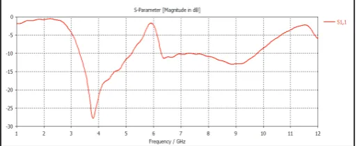
Fig. 2: Return Loss of Antenna Array
V. Conclusion
This paper has attempted to provide a view of a dynamic and
fast growing industry at a level where nonexperts in the field
are able to appreciate it. After presenting an overview of mobile communications, this paper showed the current state of research in the use of antenna arrays to meet the projected demand of increased channel capacity by describing how an array may be used in various mobile communications systems and MIMO systems. Many theoretical, experimental, and computer-simulated studies were cited to show the feasibility of such systems.
References
[1] Lal C. Godara,"Applications of Antenna Arrays toMobile Communications, Part I:Performance Improvement, Feasibility, and System Considerations”, Proceedings of The IEEE, Vol. 85, No. 7, July 1997
[2] John Huang,"A Technique for an Array to Generate Circular Polarization with Linearly Polarized Elements”, Ieee Transactions on Antennas and Propagation, Vol. Ap-34, No. 9, September 1986
[3] P.S. Hall,"Application of sequential feeding to wide bandwidth circularly polarised microstrip patch arrays”, IEE Proceedings, Vol. 136, Pt. H, No. 5, October I989
[4] A. Balanis,"Antenna Theory: A Review”, Proceedings of the IEEE Vol. 80, No. 1, January 1992.
[5] David M. Pozar,“Microstrip Antennas”, Proceedings of the IEEE Vol. 80, No 1, January 1992
[6] David Sinchez-Hemindez, Ian D. Robertson,“Analysis and Design of a Dual-Band Circularly Polarized Microstrip Patch Antenna”, IEEE Transactions on Antennas and Propagation, Vol. 43, No. 2, February 1995.
[7] John Huang,"A Ka-Band Circularly Polarized High-Gain Microstrip Array Antenna”, IEEE Transactions on Antennas And Propagation, Vol. 43, No. 1, January 1995
[8] Naftali Herscovici, Zvonimir Sipus, Davor Bonefa", Circularly Polarized Single-Fed Wide-Band Microstrip Patch”, IEEE transactions On Antennas And Propagation, Vol. 51, No. 6, June 2003.
[9] Ko Han Lu The-Nan Chang,"Circularly Polarized Array Antenna With Corporate-Feed Network and Series-Feed Elements”, IEEE Transactions On Antennas And Propagation, Vol. 53, No. 10, October 2005
[10] Nasimuddin, Karu P. Esselle, A. K. Verma,“Wideband Circularly Polarized Stacked Microstrip Antennas”, IEEE Antennas and Wireless Propagation Letters, Vol. 6, 2007.
[11] Symon K. Podilchak, Mathieu Caillet, David Lee,Yahia M. M. Antar, Lucia C. Y. Chu, Jeff Cain, Mark Hammar,Dwight Caldwell, Elgin Barron,” A Compact Circularly Polarized Antenna Using an Array of Folded-Shorted Patches”, IEEE Transactions on Antennas and Propagation, Vol. 61, No. 9, September 2013.
[12] Changhong Zhang, Xianling Liang, Xudong Bai, Junping Geng, Ronghong Jin,“A Broadband Dual Circularly Polarized Patch Antenna With Wide Beamwidth”, IEEE Antennas And Wireless Propagation Letters, Vol. 13, 2014.
[13] Adam Narbudowicz, Matthias John, Vit Sipal, Xiulong Bao, Senior Max J. Ammann,“Design Method for Wideband Circularly Polarized Slot Antennas”, IEEE Transactions on Antennas and Propagation, Vol. 63, No. 10, October 2015. [14] Yuhai Jiang, Wen Geyi, Lingsheng Yang, Hucheng Sun,
“Circularly-Polarized Focused Microstrip Antenna Arrays”, IEEE antennas and wireless propagation letters, Vol. 15, 2016.
[15] Ramesh Garg, Prakash Bhatia, Inder Bahl, Appisak Ittipiboon “Microstrip Antenna Design Handbook”, Arteck house inc, 2001.
[16] J R James, P S Hall,"Hand Book of Microstrip Antennas”, Peter Peregrinus Ltd., London, United Kingdom
[17] C A Balanis,"Antenna theory design and analysis”, John Wiley & Sons, Inc.
[18] Deeparani Mishra, Sikha Mishra, Mihir N. Mohanty, “Estimation of MIMO-OFDM Based Channel for High Data Rate Wireless Communication”, International Journal of Computer Science and Information Technologies, (IJCSIT), Vol. 2 (3), May, 2011, pp. 1263-1266.
[19] Mihir Narayan Mohanty,“Performance Analysis of Mimo Wireless System with Array Antenna”, ARPN Journal of Engineering and Applied Sciences, Vol. 8, No. 10, pp. 806-810, Oct. 2013, ISSN 1819-6608.
[20] Anindita Das, Mihir Narayan Mohanty, “Design of Optimized U-Slot Microstrip Antenna for Multiband Communication”, IJAER, ISSN 0973-4562 Vol. 10, No. 44 (2015), pp. 31167-31174.
Sarmistha Satrusallya has completed his Master of Technology in Electronics and Communication engineering from
‟KIIT University”, Bhubaneswar, in
2008.
Mihir Narayan Mohantyhas published more than 100 papers in International/ National journals and Conferences along with approximately 20 years of teaching experience.
He is an active member of many professional societies like IEEE, IET, IETE, EMC & EMI Engineers India, IE (I), ISCA, ACEEE, IAEng etc. He has received his M.Tech. degree in Communication System Engineering from the Sambalpur University, Sambalpur, Odisha and Ph.D. in Applied Signal Processing from BijuPattanaik Technical University, Odisha. He is currently working as an Associate Professor and was Head in the Department of Electronics and Instrumentation Engineering, Institute of
Technical Education and Research, Siksha O‟ Anusandhan