Implementation of Intelligent Controllers in Direct
Torque Controlled Permanent Magnet
Synchronous Motor
Dr. A. Sudhakar1
1
Associate Professor, Madanapalle Institute of Technology and Science, Madanapalle, AP, India.
Abstract: In recent years, permanent magnet synchronous motors (PMSM) have gained versatile industrial applications, because of simple structure, high efficiency, and ease of maintenance. But these motors have a nonlinear mathematical model. To resolve this problem several studies have suggested the implementation of vector control (VC) and direct torque control (DTC) with soft-computing (SC) techniques. This paper presents implementation of Neural controller in DTC of PMSM. This paper aims to present back propagation learning method implemented in Recurrent Neural Network architecture to control torque ripple and harmonic mitigation in stator current waveform compared to previous techniques. The outputs of Intelligent controller based DTC mechanism is compared with that of classical DTC and the results demonstrate the influence of Intelligent controllers is improved compared to classical DTC topology. The system is also verified and proved to be operated efficiently with reduced torque ripple and reduced Total Harmonic Distortion(THD) value in stator current. The proposed method validity and effectiveness has been verified by computer simulations using Matlab/Simulink®. These results are compared with the ones obtained with a classical DTC using PI speed controller.
Index Terms: PMSM, DTC, Neural controller, torque ripple, THD value
I. INTRODUCTION
In recent years PMSM have become a leading machine in the industrial applications because it has simple and rugged structure, high maintainability and economy, it is also robust and immune to heavy overloading, etc[1]. Direct torque control method is one of the newest control systems for PMSM based on vector control of electric motors [2]. This method was invented originally for induction motor (IM) by Takahashi[3] and Depenbrock [4] in 1986 and 1988 respectively, and then a lot of improvements over the proposed method have been made by other researchers for PMSM. The DTC of a PMSM motor involves the direct and independent control of the flux linkage and electromagnetic torque, by applying appropriate voltage switching vectors to the converter. Direct Torque Control describes the way to control torque, directly based on the electromagnetic state of the machine. DTC can be pertinent to asynchronous machines, permanent magnet machines etc. DTC is the first technology to control the motor variables of torque and flux [9]. Because torque and flux are motor parameters that are being directly controlled, there is no need for a modulator, as used in PWM drives, to control the frequency and voltage. A modified DTC scheme that utilizes space vector modulation (SVM)was reported in [10].
vector selection scheme, to reduce the torque ripple by regulating the flux and torque errors, are proposed When compared to the classical DTC scheme, the proposed technique can suppress torque and flux ripples significantly.
The organization of this paper depart as, Section 2 will present concept of conventional DTC and Section 3 describes the implementation of DTC-ANN technique. The simulation and experimental results will be presented in Sections 4 and conclusions are stated in Section 5.
II. CONVENTIONAL DTC METHOD
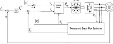
The conventional DTC technique depends on the torque and flux levels, so the torque margins permit the torque ripples. The conventional DTC method applied to PMSM is shown in Fig 1. Its applied components have a block of estimator of torque and flux as well as the detector of sector. A set level (ψsref = 1.3797wb) to the reference flux and the reference electromagnetic torque
obtained from the error between reference speed and actual speed is applied. In the performed simulation, stator flux and torque references are compared to the values calculated in the drive and errors are sent to the hysteresis comparators. Based on the error between reference torque and estimated torque, error between constant flux value and estimated flux value and the load angle δ
[image:2.612.214.400.274.346.2]between rotor flux and stator flux the corresponding voltage vector is selected as input to the inverter to achieve control of torque parameter of PMSM.
Fig 1 : Conventional DTC applied to PMSM
The electromagnetic torque can be estimated from the below expression :
3
2
e d q q d
T
P
i
i
(1)Where the symbols of parameters are as follows:
ψd -D axis stator magnetic flux, ψq -Q axis stator magnetic flux,
id-d-axis stator current,
iq-q-axis stator current,
Te -Electromagnetic torque,
p -pole number.
III. PROPOSED METHOD
The neural controllers implemented in DTC of PMSM is shown in Fig 2.The error obtained from reference flux and estimated flux is given as input to the Artificial neural controller and the signal Vx is obtained as the output. The error between reference torque
and estimated torque is given as input to another Artificial Neural controller and the signal Vy is obtained as the output. Based on
the output signals Vx and Vy obtained from the Neural controllers and the load angle δ between stator flux and rotor flux the
corresponding voltage vector is selected which controls both flux and torque.
[image:2.612.202.409.619.700.2]The structure of the proposed recurrent neural network used for estimation is indicated in Fig.3, the network has three layers, i.e., input layer, hidden layer, and the output layer. The circles in the network represent the neurons. Whereas the hidden layer in the present design has two neurons. The topology can be defined as one-two-one network. The network is fully connected, i.e., the output of each neuron is connected to all the neurons in the forward layer through weights. Besides, a bias signal is coupled to all the neurons of the hidden and output layers through a weight.
Fig 3: RNN Architecture Proposed As the Neuro Controller
Learning process depends on training pattern. The Training algorithm of back propagation applied to the RNN Architecture and algorithm is presented below
A. Training Algorithm
Initialization of weights
1) Step1:initialize weights to small random values
2) Step2:while stopping condition is false do step 3 to10
3) Step3:for each training pair do step 4 to 9
phase 1
Feed forward:
4) Step4:Each input receives the input signal xi transmits this signal to all units in layer above i.e. hidden units and having weights
vj.
5) Step5:Each hidden unit (yj, j=1…..p) Sums its weighted input signals.
1, 1
(
)
n
inj oj i ij is i s
y
v
x v
v
(2)Applying activation function
y
j
f y
(
inj)
and sends this signal to all neurons in the layer above i.e., output units.6) Step 6: Each output unit (zk, k=1…m) sums its weighted input signals with weights wk.
1
p
ink ok j jk
j
z
w
y w
(3)And applies its activation function to calculate the output signals
z
k
f z
(
ink)
(4)phase 2
Back propagation of errors:
7) Step 7: Each output unit (zk, k=1…m) receives a target pattern tk corresponding to an input pattern error information term is
calculated as
(
) (
)
k
t
kz
kf z
ink
(5)1
m
inj k jk
k
w
(6)The error information term is calculated as
j inj
y
inj
(7)1 m
ink ok k jk k
z
w
y w
(8)phase 3
Updation of weights and biases:
9) Step 9:Each output unit (zk, k= 1 . . . ., m) updates its bias and weights (j=0, . . . p)
The weights correction term is given by
jk k j
w
y
(9)And the bias correction term is given by
ok k
w
(10) Therefore,(
)
(
)
jk jk jk
w
new
w
old
w
(11)(
)
(
)
ok ok ok
w
new
w
old
w
(12)Each hidden unit (yj, j= 1. . . p) Updates its bias and weights (i= 0…n), the weight correction term
ij j i
v
x
(13)The bias correction term
oj j
v
(14)Therefore,
(
)
(
)
ij ij ij
v new
v old
v
(15)(
)
(
)
oj oj oj
v
new
v
old
v
(16)Neuron in the output layer. A network has been structured, and then the network is ready to be trained. To start this process the initial weights are chosen randomly. Then the training begins.
The training procedure used to train the neural network is as follows:
a) Simulate the synchronous motor drive system in MATLAB/SIMULINK and generate the input/output data. The input data correspond to the error between reference torque and estimated torque for neural controller with Vy output signal. The error
between reference flux and estimated flux is fed as input data to neural controller with Vx as output signal.
b) Normally network activation functions are bounded between -1 and +1. Normalization of data is considered to avoid saturation.
c) Load the torque and flux error data as inputs to the Artificial Neural Network and train the network according to the EBP algorithm.
d) The initial weights of the network are assumed randomly. [-1, 1].
e) An input/output pattern is selected based on conventional method. For the given input data pattern calculate the network output and compare with the desired data output to derive the error pattern.
f) From the error pattern, compute and readjust the network weights by the Error Back propagation algorithm (EBP) so that the new error is smaller. In this algorithm learning rate α and momentum term η are used.
h) After completing the training, test the network performance with different input patterns is performed to ensure successful training.
i) At the output of the ANN, the actual outputs are compared with the desired output to find the error, which is then used, in the error back propagation Algorithm (EBP).
j) The error calculated above is used to update the weights of the entire net until the error is minimized.
10) Step 10:Test the stopping condition. The stopping condition may be the minimization of errors
B. Training Procedure
The recurrent neural network is as shown in Fig.3. This network consists of 1-2-1 architecture i.e., it is designed with 1 neuron in the input layer, 2 neurons in the hidden layer, and 1 in the output layer.
IV. RESULTS
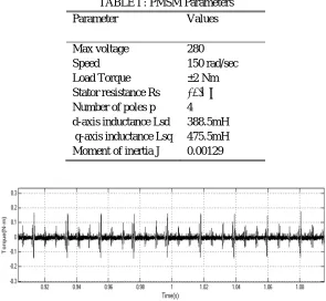
[image:5.612.156.451.249.521.2]Simulation results for a DTCsystem when controlling the permanent magnet synchronous machine for following parameters:
TABLE I : PMSM Parameters Parameter Values
Max voltage 280 Speed 150 rad/sec Load Torque ±2 Nm Stator resistance Rs 19.4 Ω
Number of poles p 4 d-axis inductance Lsd 388.5mH
[image:5.612.164.454.565.703.2]q-axis inductance Lsq 475.5mH Moment of inertia J 0.00129
Fig 4 : Conventional DTC : Torque ripple at Steady state
Fig 6 : Proposed DTC : Torque ripple at Steady state
Fig 7 : Proposed DTC : stator current Total Harmonic Distortion % at Steady state
The torque ripple and stator current Total Harmonic Distortion(THD)% value of stator current in steady state for conventional and proposed methods is represented in Figs 4-7.The torque ripple content in proposed method is reduced compared to conventional DTC method. The THD values obtained for stator currents meet the IEEE 519 standards. The THD % value of proposed method is reduced compared to conventional DTC method
TABLE II : Comparison of Conventional and Neural controller based DTC methods Method Torque ripple % THD value Conventional DTC method 35.2% 4.37% Neural controller based DTC method 7.6% 1.17%
From Table 2 it is clear that Neural controller based DTC method gives reduced torque ripple and % THD value of stator current compared to conventional DTC method.
V. CONCLUSION
The Direct Torque Control (DTC) is an important alternative method for the PMSM motor drive, with its high performance and simplicity. The DTC applied to PMSMmachine fed by a 3-level inverter in conventional method presents good performance and undulations reduction. In this case, intelligent techniques were developed in order to replace the conventional DTC topology. In this paper, neural network controllers are proposed for DTC. The proposed method gives efficient response with reduced torque ripple and decreased %THD value of stator current. The performance of the neural network DTCscheme shows learning capability of neural networks and the proposed method can be considered as better technique.
REFERENCES
[1] Peter Vas. “Sensorless Vector and Direct Torque Control”, Monographs in Electrical and Electronic Engineering, Oxford University Press, 1998,ch.4. [2] N. P. Quang, J. –A. Dittrich. “Vector Control of Three-Phase AC Machines”, Power Systems, Springer, vol 4, pp. 1612-1287,Jan 2008.
[3] Hany M. Hasanien, “Torque ripple minimization of permanent magnet synchronous motor using digital observer controller”, Energy Conversion and Management. vol 51,pp 98-104,May 2010.
[4] Suman Maiti, Chandan Chakraborty, Sabyasachi Sengupta."Simulation studies on model reference adaptive controller based speed estimation technique for the vector controlled permanent magnet synchronous motor drive”, Simulation Modelling Practice and Theory. vol 17 : pp 585-596,July 2009.
[5] B.Bossoufi,M.Karim,S.Ionita, A.Lagrioui. “Performance Analysis of Direct Torque Control for Permanent Magnet Synchronous Machine” in Proc. IEEE-SIITME’ Pitesti, Romania , vol 14 no 2,pp 275-280, 23-26 Sep 2010,
[6] R.Kumar, R.A.Gupta, S.V.Bhangale, H.Gothwal. “Artificial Neural Network based Direct Torque Control of Induction motor drives”, IETECH Journal of Electrical Analysis, IETECH Publications, vol 12 no 3,pp159 – 165, Feb 2008
[image:6.612.148.457.398.441.2][8] B.Bossoufi, M.Karim, S.Ionita,A.Lagrioui, G.Iana. “Matlab & Simulink Simulation with FPGA-Based Implementation Sliding Mode Control of a Permanent Magnet Synchronous Machine Drive.” WSEAS Transactions on Systems and Control, vol 3 no 6,pp 92-103, May 2011.
[9] L. Tang, L. Zhong, M. F. Rahman, and Y. H. “A Novel Direct Torque Control for Interior Permanent Magnet Synchronous Machine Drive System with Low Ripple in Flux and Torque and Fixed Switching Frequency,” IEEE Trans. Power Electronics, vol 19 pp 346-354,June 2004.
[10] K. L. Shi, T. F. Chan, Y. K. Wong, and S. L. Ho "Estimation of an Induction Motor Drive Using an Optimized Extended Kalman Filter". IEEE Transaction on Industrial Electronics, vol 49 no 1,Sep 2002.
[11] D.V.Naga Ananth ."Artificial Neural Network Based Direct Torque Control for Variable Speed Wind Turbine Driven Induction Generator" International Journal of Computer and Electrical Engineering,vol 3 no 6,pp 880-889,Jan 2011.