Simulation of SC-FDMA System with Space
Time Block Coding (STBC)
Navjot Kaur
1, Er.Neetu Gupta
2M.Tech Student, Global Institute of Management & Emerging Technologies (GIMET), Amritsar, India1 Assistant Professor, Global Institute of Management & Emerging Technologies (GIMET), Amritsar, India2
ABSTRACT-Throughout wireless communication systems, Orthogonal Frequency Division Multiplexing (OFDM) and also Single-Carrier Frequency Division Multiple Access(SC-FDMA) contributes a significant part. It has been adopted by a variety of future mobile communication standards like WiMAX, Long-term Evolution (LTE), LTE-Advanced and also Ultra Mobile Broadband (UMB) and many others. SC-FDMA can be interpreted as a linearly precoded OFDM scheme in the sense that it has an additional DFT processing step preceding the standard OFDM processing.SC-FDMA is a technique which utilizes single carrier modulation at the transmitter and frequency domain equalization at the receiver and has almost similar performance and essentially the same overall structure as those of an OFDM system.Its one most important benefit over OFDM is that it has lower peak-to-average-power-ratio(PAPR).It is an attractive substitute to OFDM, especially in the uplink communications where lower PAPR greatly benefits the mobile terminal in terms of transmit power efficiency. SC-FDMA is currently a working theory for the uplink multiple access scheme in 3GPP Long Term Evolution (LTE).This work presents the simulation of SC-FDMA in GUI MATLAB.In this,we have used an application of Space Time Block Coding(STBC) for SC-FDMA in order to combat severe effects of fading.
KEYWORDS:SC-FDMA,OFDM,GUI,PAPR,STBC.
I. INTRODUCTION
With the widespread of multimedia applications, demand for higher data rate is increasing rapidly,which is leading to utilization of a wider transmission bandwidth. Frequency selectivity of the channel becomes more severe and thus the problem of inter-symbol interference (ISI) becomes more severe with a wider transmission bandwidth.Time domain equalization in the form of tap delay line filtering is performed to eliminate ISI in a conventional single carrier communication system.However, in case of a wide band channel, the length of the time domain filter becomes prohibitively large to perform equalization since it linearly increases with the channel response length. One way to lessen the frequency-selective fading seen in a wide band channel is to use a multicarrier technique which subdivides the entire channel into smaller sub-bands, or subcarriers.
Orthogonal frequency division multiplexing (OFDM) is a multicarrier modulation technique which utilizes orthogonal subcarriers to transfer information. In the frequency domain, since the bandwidth of a subcarrier is designed to be smaller than the coherence bandwidth, each sub channel is seen as a flat fading channel which simplifies the channel equalization process. In the time domain, by splitting a high-rate data stream into a number of lower-rate data stream that are transmitted in parallel, OFDM resolves the problem of ISI in wide band communications [1]. But OFDM has its negative aspects also like high peak-to-average power ratio (PAPR), high sensitivity to frequency offset, and a need for an adaptive or coded scheme to overcome spectral nulls in the channel [2], [3].
uplink of 3GPP Long Term Evolution (LTE) and shown some research results on its BER and PAPR characteristics.Like other multiple access schemes (TDMA, FDMA, CDMA, OFDM), it deals with the assignment of multiple users to a shared communication resource. SC-FDMA can be interpreted as a linearly precoded OFDM scheme, in the sense that it has an additional DFT processing step preceding the conventional OFDM processing[9].Although the performance gap is not much between OFDM and SC-FDMA,SC-FDMA's additional advantage of low PAPR makes it a favourite especially for uplink wireless transmission in future mobile communication systems where transmitter power efficiency is of supreme importance. The transmission processing of SC-FDMA is very similar to that of OFDM[4].
The remaining part of this paper is organized as follows: Section II discusses the related work to this paper. Section III gives a brief overview of single carrier frequency division multiple access (SC-FDMA),space-time- block coding(STBC) and graphical user interface(GUI).Section IV explains the implementation of SC-FDMA with STBC coding in GUI in MATLAB. Section V shows the results of BER performance and PAPR performance of SC-FDMA signals. Section VI gives the conclusion.
II. RELATEDWORK
OFDM is a widely used multicarrier modulation scheme which is being used in several applications as it provides high data rates, efficient utilization of the spectrum. OFDM combined with MIMO has been used in several communication systems [1][6][7][10].Further more developments have been done in previous years. OFDM is used with space time block coding(STBC) as a downlink baseband receiver for mobile WMAN in [2].Also OFDM has been used with STBC as an FPGA-based transceiver for WiMAX 802.16e standard[3].In all these researches BER and SNR has been calculated. And from all these we have concluded that OFDM is a quite efficient modulation technique as it provides several benefits. Despite of these it also have some disadvantages. Its one major disadvantage is high peak-to-average-power ratio(PAPR)[4][5].In the previous years research works done yet, we have seen that SC-FDMA(single carrier frequency division multiple access) system overcomes this drawback to a great extent[5][9].SC-FDMA lowers down the PAPR, in addition to it, it also enhances bit error rate and efficienc y of the system. It can be interpreted as a linearly precoded OFDM scheme, in the sense that it has an additional DFT processing step preceding the standard OFDM system[4][5].In this research, we have used the application of STBC with SC-FDMA. In this, we have used STBC 2x2 MIMO system, which has two transmit antennas and two receive antennas respectively. We have simulated SC-FDMA with STBC in GUI MATLAB.GUI is graphical user interface, which is a pictorial interface to a program. We, thus have got results i.e.BER vs SNR performance and PAPR performance which shows that SC-FDMA system performs quite better and efficient than the OFDM system.
III. SUMMARYOFSC-FDMA,STBCANDGUI
A.SC-FDMA fundamentals
SC-FDMA is a single-carrier frequency division multiple access scheme.It deals with the assignment of multiple users to a shared common resource.SC-FDMA can be interpreted as a linearly precoded OFDM scheme in the sense that it has an additional DFT processing step preceding the standard OFDM processing.It has drawn great attention as an attractive alternative to OFDM especially in the uplink communication where lower PAPR greatly benefits the mobile terminal in terms of transmit power efficiency in addition to power amplifier‟s reduced cost.It has been adopted as the uplink multiple access in 3GPP Long Term Evolution (LTE) or Evolved UTRA (E-UTRA).[5]
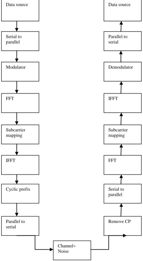
introduced between blocks of symbols in view to efficiently eliminate inter-symbol interference from time spreading (caused by multi-path propagation) among the blocks[6].In SC-FDMA, multiple access among users is made possible by assigning different users different sets of non-overlapping fourier-coefficients (sub-carriers). This is achieved at the transmitter by inserting (prior to IFFT) silent fourier-coefficients (at positions assigned to other users), and removing them on the receiver side after the FFT. Figure 1 shows the basic block diagram of single-carrier frequency division multiple access (SC-FDMA).
Figure 1: Block diagram of SC-FDMA system
Data source Data source
Serial to parallel
Modulator
FFT
Subcarrier mapping
IFFT
Cyclic prefix
Parallel to serial
Parallel to serial
Demodulator
IFFT
Subcarrier mapping
FFT
Serial to parallel
Remove CP
B.STBC fundamentals-
STBC is actually space-time-block codes. The original scheme was dependant on trellis codes however the simpler block limitations were utilised by Sivash Alamouti, in addition to later Vahid Tarokh, Hamid Jafarkhani in addition to Robert Calderban to produce space–time block-codes (STBCs). Space-time block codes (STBC) [2] are a generalized version of Alamouti scheme [3],but have the similar key features. These codes are orthogonal and can achieve full transmit diversity specified by the number of transmit antennas. In other words, space-time block codes are a complex version of Alamouti‟s space-time code, where the encoding and decoding schemes are the same as there in the Alamouti space-time code on both the transmitter and receiver sides. Space-time block codes were designed to achieve the maximum diversity order for the given number of transmit and receive antennas subject to the limitation of having a simple linear decoding algorithm. This has made space-time block codes a very popular and most widely used scheme[9].
In STBC, the data stream is encoded in blocks which is going to be transmitted, and that are usually distributed among spaced antennas and across time. While it is vital to have several transmit antennas, it's not necessary to have got multiple receive antennas, although to do this improves performance. This process of receiving diverse copies with the data is recognized as diversity reception. Space-time block codes are utilized for MIMO systems which help the transmission of multiple copies of a data stream across many antennas.In addition to this,it exploit the many received versions with the data to improve reliability of data-transfer. Space-time block coding combines the many copies of the particular received signal in one of the most favorable way to extract the maximum amount of information from each as possible. In this, the data is encoded in blocks prior to transmission. These data blocks are then distributed among the multiple antennas (which are usually spaced apart in order to decorrelate the transmission paths) plus the data is furthermore spaced across time[3][9].An STBC is generally represented by a matrix. Each row represents a time slot and every column represents one antenna's transmissions over time.
Transmit antennas Time-slots
TnT T T nT nTS
S
S
S
S
S
S
S
S
...
...
...
2 1 2 22 21 1 12 11Here Sij is the modulated symbol to be transmitted in time slot i from antenna j.There are T time slots, nT transmit
antennas and nR receive antennas. Block is considered to be of length „T‟.
Alamouti's code:-In this paper we have used STBC‟s Alamouti 2X2 MIMO transceiver.Alamouti invented the simplest
of all the STBCs in 1998,although this term "space–time block code" wasn‟t coined by himself[2].It was designed for a two-transmit antenna system and has the coding matrix:
C2=
* 1 * 2 2 1c
c
c
c
Where * indicates complex conjugate.
C.GRAPHICAL USER INTERFACE(GUI)-
A graphical user interface is a pictorial interface to a program.It is a tool used in MATLAB.It can construct programs easy by providing them with a stable look and with impulsive controls like pushbuttons, sliders, menus, list boxes and so forth. The three main elements required to create a MATLAB GUI are components, figures and callbacks.
2.Figures:Figure is a window displayed on the computer screen and the components of a GUI must be arranged within a figure. Empty figures can be formed with the figure function. It can also be used to grip any mixture of components. 3.Callbacks:In this if a user clicks on a button, then that event must sources the MATLAB code which implements the function of the button which has to be executed. So the code executed in response to an event is known as a call back. There must be a callback for implementing the function of each graphical component on the GUI[8].
IV. SYSTEM IMPLEMENTATION
In this work, we have simulated single carrier frequency division multiple access(SC-FDMA) with space time block codes (STBC) in MATLAB. Here we have used MATLAB version 7.10.0(R2010a).In MATLAB, there is a tool named graphical user interface(GUI) which we have used for implementing SC-FDMA with STBC coding. In this work,the design is divided into two subsystems. At the transmitter side: QPSK for symbol mapping, STBC encoder, IFFT. The receiver consists of an FFT, STBC decoder and the QPSK.[3]Following functions have been performed to implement this communication system:-
A.SIGNAL GENERATION:-Generate a signal. The generated signal will then further be applied certain conversions and
at the end error will be calculated on the generated signal.
BMODULATION:-After generating a signal the next process to be applied on that generated signal is modulation. Now,
apply QPSK and BPSK modulation on the generated signal.
C.SERIAL TO PARALLEL CONVERSION:-The next step is serial to parallel conversion.The serial data has been
converted to parallel bits of data.
D.FFT/IFFT:-In this,FFT(Fast Fourier Transform) and IFFT(Inverse Fast Fourier Transform) are used for
implementation of SCFDMA-STBC in MATLAB.
E.PARALLEL TO SERIAL CONVERSION:-Now the parallel data needs to be converted back to the serial data.So we
will apply parallel to serial conversion to the signal.
F.STBC ALAMOUTI’S CODE:- Then add cyclic prefix(CP) to the signal and generate STBC Alamouti‟s code.In
this,STBC encoder uses two transmit antennas and two receive antennas based on Alamouti scheme.
G.GENERATION OF NOISE:- Now generate AWGN (Additive White Gaussian Noise) and Rayleigh Fading channel.
This generated noise is now to be added to the signal that was previously generated and had undergone certain conversions. So, add noise to the generated signal.
H.EQUALIZATION:-Receiver equalization is then done.
I.QPSK DEMODULATION:-The demodulation is then applied. That is demodulate the generated signal. After the
signal has been applied all the conversions and it has been modulated, error needs to be calculated.
J.CALCULATION OF ERROR:-Now calculate the error in the signal.
V. SIMULATION RESULTS AND DISCUSSION
(a) (b)
Figure 2:BER vs SNR performance of SC-FDMA-STBC signal with (a)QPSK Modulation and (b)BPSK Modulation
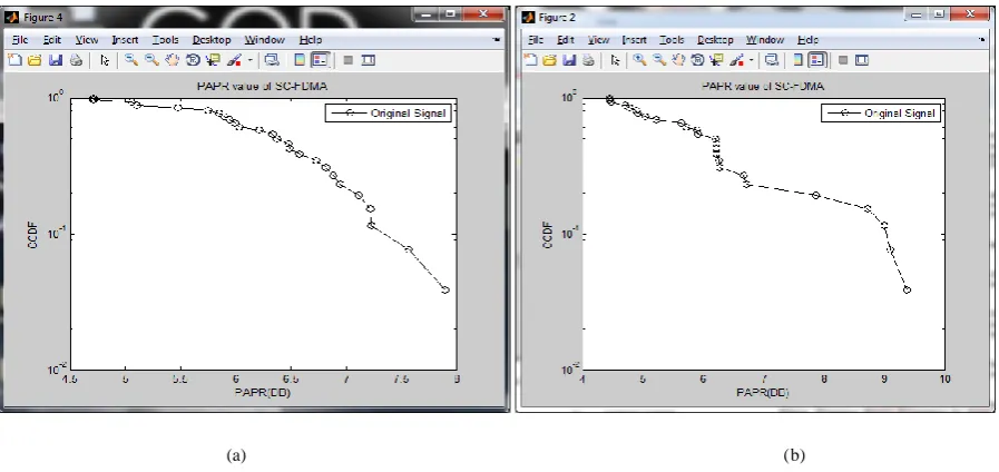
Thus we have seen that BER vs SNR performance with both techniques i.e. QPSK and BPSK is quite efficient in SC-FDMA system. After this we have calculated its PAPR value with the same QPSK and BPSK modulation schemes respectively. So it has been shown in the results given below that PAPR(peak-to average-power ratio) value is quite lower down in this system. The PAPR performance of this system is given below:
(a) (b)
Figure 3:PAPR Performance of SCFDMA-STBC signal with (a)QPSK Modulation and (b)BPSK Modulation
VI. CONCLUSION
better in case of BER and PAPR than the previous work done yet(OFDM,CDMA,TDMA etc).Its BER vs SNR performance is quite better than the OFDM system. Also its PAPR characteristic is lower than the OFDM system.In future, further advanced techniques are developing for further enhancement of BER and PAPR value.
REFERENCES
[1] S. J. Vaughan-Nichols, “OFDM: Back to the Wireless Future” IEEE Computer, pp. 19–21, Dec. 2002.
[2] H.-y' Chen, J.-N. Lin, H.-S. Hu, and S.-J. Jou, "STBC-OFDM downlink baseband receiver for mobile WMAN," Very Large Scale Integration (VLSI) Systems, IEEE Transactions on, vol. 21, no. 1, pp. 43-54, 2013.
[3] Sugondo Hadiyoso, “Design of an FPGA-Based OFDM-STBC Transceiver for WiMAX 802.16e Standard”in 2014 International Conference on Information and Communication Technology(ICoICT) on 978 1-4799-3580-2/14/$31.00 2014,IEEE.
[4]Tae-Won Yune, “SC-FDMA with Iterative Multiuser Detection: Improvements on Power/Spectral Efficiency”. [5]Junsung Lim, “Channel-Dependent Scheduling of Uplink Single Carrier FDMA Systems”.
[6] M. Vani Divyatha, B. Siva Reddy, “ Design and BER Performance of MIMO-OFDM for Wireless Broadband Communications”, International Journal of Modern Engineering Research (IJMER), Vol.3, Issue.3, May-June. 2013 pp-1382-1385 ISSN: 2249-6645.
[7]Mr.Sivanagaraju.V,Dr.Siddaaih.P, “Comprehensive Analysis of BER and SNR in OFDM Systems” ,International Journal of Innovative Research in Computer and Communication Engineering,Vol.2,Issue 2,February 2014.
[8]Chapman, Stephen J., MATLAB Programming for Engineers, Brooks Cole, 2001.
[9]Santumon.S.D.and B.R.Sujatha, “Space-Time Block Coding for Wireless Networks”, International Journal of Distributed and Parallel Systems(IJDPS), Vol.3, No.4, July 2012.
[10] Vibha Rao,T. Malavika K., “Performance analysis of MIMO-OFDM for multiple antennas” ,International Journal of Advanced Research in Electrical,Electronics and Instrumentation Engineering,Vol.3,Issue 5,May 2014.
[11]H.G. Myung and D.J. Goodman, “Single carrier FDMA: a new air interface for long term evolution,” Wireless Communications and Mobile Computing, 2008.