Novel Method for Generating Electromagnetic Vortex Wave
Gengqi Zheng1, *, Baohua Sun1, and Shuhong Gong2
Abstract—Electromagnetic (EM) vortex wave carries orbital angular momentum (OAM), which has been proposed for improve anti-interference performance, spectral efficiency, and message capacity in radio communications. Multiple sub-channels of propagation are achieved by different twisting degrees of EM wave. In order to develop the theory and technique of the OAM, works must be done to study the generation of vortex wave. There exist several devices to generate vortex wave, such as phase plate, holographic diffraction gratings, spiral reflectors, and antenna arrays. In this paper, based on typical parabolic antenna, a new approach to generate vortex wave carrying OAM in radio frequency through coating specific controllable complex dielectric constant material on parabolic antenna is introduced. From the results of the proposed antenna, we conclude that parabolic antenna with materials arranged by a specific rule on the reflector has capacity of generating an EM wave with clockwise and anti-clockwise phase distributions around beam-axis. The new method generating OAM is simple and suitable to be well applied in wireless electronic technology.
1. INTRODUCTION
Mobile wireless communication becomes indispensable in the information era in human society. High speed wireless communication system is bound to utilize more bandwidth. Meanwhile, to increase the capacity of communication, extensive studies and experiments have been carried out using multiplexing of independent degrees of freedom, such as time, space, code type, and polarization. Although orthogonal frequency division multiplexing (OFDM), code division multiple access (CDMA), and space-time code technique are widely used, a new technique is urgently needed to improve the spectrum efficiency. JournalNature has reported the OAM, which applies quantum mechanics to mobile wireless communication, which can greatly broaden the bandwidth of wireless communication. According to classical Maxwell’s electromagnetic theory, EM wave carries both energy and momentum, including linear momentum and angular momentum. Angular momentum consists of spin angular momentum (SAM) and orbital angular momentum (OAM). On the basis of electromagnetics, SAM corresponds to polarization, while OAM describes the spatial coordinate dimension of horizontal rotation mode of the beam, which corresponds to the spatial structure of wavefront. Usually, plane wave has an OMA of zero, and its phase maintains constant in a plane. However, the OAM of a vortex wave is not zero, and its phase β follows a linear variation along the azimuthal angle ϕ: β = lϕ. Here, l is an integer called “topological charge” theoretically. Hence, the field intensity varies asf(r)·e−jkz·e−jlϕ, wherek
is the wave number, z the distance along the propagation, and f(r) the field intensity variation along the radial coordinate.
As we all know, OAM is employed as a new degree of freedom for multiplexing to expand the capacity of the information transmission and raise the efficiency of the channel [1, 2]. In 2007, Thid´e et al. first applied OAM in the low frequency and verified that the phase array antenna was well applied
Received 11 November 2018, Accepted 28 March 2019, Scheduled 9 May 2019
* Corresponding author: Gengqi Zheng ([email protected]).
1 Key Laboratory of Science and Technology on Antennas and Microwaves, Xidian University, Xi’an, Shaanxi 710071, China. 2
to generate vortex wave [3]. Mohammadi et al. simulated the transmission and reception properties of the electromagnetic vortex wave by a uniform circular array antenna, which solved the correct measurement of OAM mode without receiving the whole vortex beam [4]. The research team reported their findings in the laboratory [5, 6]. Thid´e and his colleagues realized a communication between dual channels at the same time over the same frequency band, in which a Yagi-Uda antenna was utilized for transmitting quasi-TEM wave, and a spiral antenna was utilized for transmitting vortex wave [7]. In [8], an elliptical patch antenna working on the right-handed (RH) CP TM21 mode effectively radiated a vortex electromagnetic wave with a first order OAM. Deng et al. used a Vivaldi antenna array to generate a vortex electromagnetic wave [9]. Bai t al. successfully produced an electromagnetic vortex waves by using rectangular patch in a ring antenna array [10]. Spinello et al. demonstrated a 32-Gbit s−1 millimeter-wave link over 2.5 meters with a spectral efficiency of ∼ 16 bit s−1 Hz−1 using four independent OAM beams [11]. In [12], a novel horn antenna was presented to generate electromagnetic waves carrying OAM by using a circular waveguide. Shi et al. presented a novel ultrathin slot-based planar-spiral phase plate (planar-SPP) which has ability to generate electromagnetic waves carrying OAM [13]. [14] proposes a method for broadband generation of the OAM carrying beams based on the Archimedean spiral. From the present literature, four typical types of structures are utilized to generate electromagnetic wave carrying OAM, including SPP, holographic diffraction gratings, spiral reflector structures, and antenna arrays. However, those methods have some disadvantages.
(1). SPP: the broad beam antenna does not propagate to a long distance, and the reflection of the dielectric to the beam will reduce the efficiency [15, 16].
(2). Holographic diffraction gratings: due to the large divergence angle of electormagnetic wave beam, the transmission distance is short [17–19].
(3). Spiral reflector structures: it responds to a certain frequency [20].
(4). Antenna arrays: this generation method requires complex phase shift network to ensure the phase relationship among different radiation units [21–23].
This paper introduces a novel method, which coats reflecting surface elements in a parabolic antenna with a specific, controllable and complex dielectric constant material. Besides, this method is a reflection type of generating vortex wave, and it uses a coating material rather than a curved spiral parabolic antenna to achieve the spatial phase distribution of vortex wave. The simple principle of the method ensures characteristics of complete structure of the parabolic antenna, and it is efficiently compatible with wireless electronic system to achieve efficient multiplexing and networking of multi-modes electromagnetic vortex waves.
2. PRINCIPLE AND METHOD
2.1. Complex Reflection Coefficient of Dielectric
According to the basic law of electromagnetic field (by Maxwell’s equation), the constitutive relation of the electromagnetic field in the dielectric is
⎧ ⎪ ⎨ ⎪ ⎩
D=ε0εr(ω)E
B =μ0μr(ω)H
J =σ(ω)E
(1)
where D is the electric flux density, H the magnetic field intensity, B the magnetic flux density, and
J the density of free currents. ε0 = 8.854×10⁻¹²F/m and μ0 = 4π×10−7H/m are respectively the
permittivity and permeability of free space, andεrandμrare respectively relative complex permeability
and relative complex permittivity of dielectric. ω represents the frequency. In practice, the dielectric properties are always determined by the relative complex permittivityεr
εr(ω) = ε
(ω)
ε0
= ε
(ω)−jε(ω)
ε0
=εr(ω)−jεr(ω) (2)
whereεrandεr are respectively the real and imaginary components of the relative complex permittivity
εr. The complex permittivity of the dielectric is defined as ε = ε0(ε − jε), which shows the
conditions (the frequency and temperature) have drastic effects on the complex permittivity. The influence of the complex permittivity on the electromagnetic wave is presented by the attenuation and loss of electromagnetic energy, and actually, the dielectric without any loss is in existence. For high frequency dielectric, it is found that the dielectric constant is a complex number (ε=ε0(ε−jε)), in
which its real and imaginary components are the functions of frequency, and ε is positive. It acts as a breakthrough point of the proposed new method introduced in this paper, which utilizes the complex dielectric to achieve a complex reflection coefficient and produces a spiral phase factor.
As we all know, the reflection and refraction phenomena will occur on the interface of two different dielectrics when an electromagnetic wave illuminates. The reflection and refraction can be expressed by Fresnel’s law, which requires that the interface is smooth and uniform. When the wavelength of the electromagnetic wave is much longer than the roughness of the interface, the Fresnel reflection coefficients can be expressed by the dielectric constant and incident angle.
RV =
cos(θi)−
εr−sin2(θi)
cos(θi) +
εr−sin2(θi)
, RH = εr
cos(θi)−
εr−sin2(θi)
εrcos(θi) +
εr−sin2(θi)
(3)
whereεr = (ε−jε) is the relative complex permittivity of the reflecting surface, andθi is the incident
angle. RV andRH are respectively the horizontal and vertical polarization reflection coefficients, which
are denoted by subscriptsV and H.
As mentioned above, whether the incident electromagnetic wave is vertical polarization or horizontal polarization, the material with the complex permittivity indicates Fresnel reflection coefficient R =
E/E, which is a complex reflection coefficient. The reflection coefficient can be expressed in the form of pluralR =|R|ejβ, which presents that there exists a phase differenceβ between the reflection wave and incident wave after reflection occurs on the interface.
The Fresnel reflection coefficient of the dielectric surface with complex permittivity will be complex. When the dielectric surface is satisfied with the condition of Fresnel’s law of reflection, the phase rotation factor β =lϕ is related to the azimuth angle ϕ. Thus, this paper presents a parabolic antenna which utilizes phaseβ in the complex reflection coefficient to produce phase rotation factor lϕ.
2.2. Generation of Vortex Wave Based on the Rotating Parabolic Antenna
Electromagnetic vortex wave carrying OAM can form infinite dimensional Hilbert space. Theoretically, OAM multiplexing at the same carrier frequency will realize infinite transmission capability. Thus, vortex wave provides a feasible solution for the contradiction of the shortage of spectrum resources and channel capacity requirements. Compared to plane electromagnetic waves, the electromagnetic vortex wave has shorter propagation distance due to the existence of phase singularities. In microwave frequency band, parabolic antenna has capacity to realize improved gain, narrow OAM beam, and concentrated energy. Because of above advantages, the proposed method to generate vortex wave is based on the parabolic antenna, which produces the electromagnetic vortex wave by coating the specific controllable material with complex dielectric constant on the split reflecting parabolic surface.
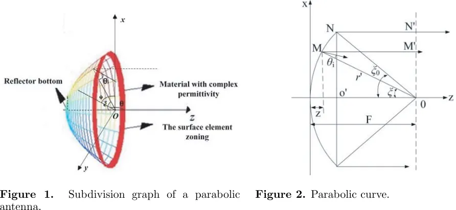
The basic working principle of a parabolic antenna is to transform spherical wave into a quasi-TEM wave with high directivity. In this paper, we intend to split the parabolic antenna. ξ is set as the angle between parabolic axis and the line that is from the source to the centre of the surface element, andϕ
is the pitch angle of reflecting surface centre with x axis as the reference axis. According to the two variables (ξ,ϕ), reflecting surfaceS of the parabolic antenna is divided into multiple surface elements, as shown in Fig. 1. The reflecting surface is divided into a number of surface elements, and we can figure out the size and location of element area on the reflecting surface by certain ξ and ϕ. ξ and ϕ
should be respectively continuous in the range of their respective intervals with a certain step. With the number of area elements increasing, the precision of results is higher.
Due to the limitations of the manufacturing process, in most of practical applications, a discrete partition is often used instead of ideal continuous division. The phase factor provided by the coated parabolic antenna is represented by:
f(ϕ) = exp
j·floor
sϕ
2π
·2lπ
s
where floor(sϕ/2π) refers to the maximum integer less than sϕ/2π, and s is the number of divided surface elements. According to the Fourier transformation theory,f(ϕ) can be written as
f(ϕ) =
+∞
−∞
cn·exp(jnϕ) (5)
wheren is an integer, and
cn=
1 2π
2π
0
f(ϕ) exp(−jnϕ)dϕ = 1 2π
2π
0
exp
j·floor
sϕ
2π
·2lπ
s
exp(−jnϕ)dϕ
For a parabolic antenna with a given vortex statel,the componentclexp(jlϕ) is desired. However,
the unnecessary components R can be written as R = 1− |cl|2, and for the most applications, it is
generally assumedR <6%, which meets the requirement of real application.
As shown in Fig. 1, we divide the parabolic reflector into plenty of surface elements, and the specific controllable materials with complex permittivity ε=ε0(εjε) are coated on the each surface element
by following the specific rule. The reflection coefficient of each surface element on the parabolic reflector is defined as R = |R|exp(jβξϕ), where βξϕ represents different angles at different surface elements.
The formula provides a phase factor for each surface element on the antenna aperture.
The radiating surface of the antenna can be regarded as an antenna array, which is composed of a plurality of continuous source antennas. The wave front of the beam has a phase difference when the electromagnetic wave is radiated from the feed parabolic. Due to the specific controllable materials on the parabolic reflector, electric field radiated by the feed is different from the electric field in the parabolic aperture. When the electromagnetic wave from the feed source is reflected by the parabolic surface, there exists a location mapping relationship between the antenna reflector and aperture of the antenna. By using the aperture field method, the radiation field of the parabolic antenna with phase rotation factor is obtained.
The far field of the parabolic antenna Ep is easy to figure out by the given distribution of the
electromagnetic field on the plane of the antenna aperture. The distribution of the electromagnetic field on the proposed antenna aperture plane is changed by reflecting surface elements with specific controllable materials.
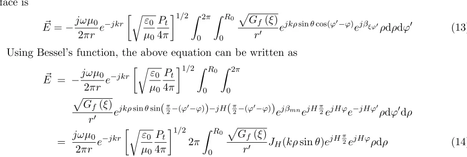
The feed of the proposed parabolic antenna is a electric basic oscillator placed along the x-axis, and the phase centre is placed on the centre of the parabolic reflector, as shown in Fig. 2, where the
MN represents the equiphase surface of the electromagnetic wave reflected by the parabolic antenna. Assuming thatEi is the incident electric field,Ptthe total radiation power, and Gf(ξ, ϕ) the feed
Figure 1. Subdivision graph of a parabolic antenna.
direction of power function, the radiated power flux density at any point on the reflecting surface is
Sf
r, ξ, ϕ= Pt 4πr2Gf
ξ, ϕ (6)
The phase centre of the feed is considered as the reference, and the power flux density can be calculated as
Sf
r, ξ, ϕ=
ε0 μ0E
2
i (7)
Besides,
Ei =
μ0 ε0
Pt
4π 1/2
Gf(ξ, ϕ)e
−jkr
r eˆi (8)
As shown in Fig. 2, the magnitude of reflected electric field at MN is assumed to be |Es|.
According to the law of energy conservation, the magnitude of reflected field Es can be obtained.
As mentioned above, this paper coats reflecting surface elements of parabolic antenna with specific controllable materials, the reflection coefficient on any surface element of the reflecting surface is defined asRξϕ =|Rξϕ|ejβξϕ
. It still takes the feed phase centre as the reference, and the electric field vector of electromagnetic wave reflected from the each surface element is
−→
Es = ˆer
μ0 ε0
Pt
4π
1/2
Gf(ξ, ϕ)
r Rξϕe
−jk(r−z+zoo) ejβξϕ
= ˆer
μ0 ε0
Pt
4π
1/2
Gf(ξ, ϕ)
r e
−jk(f+zoo)
ejβξϕ (9)
where ˆer is the unit vector of the electric field at polarization direction of parabolic aperture reflector.
Considering the polarization of the reflected electric field, the electric fields on the parabolic aperture can be divided into two components, which are along thexandy axes, respectively. However, the common parabolic aperture angle satisfiesξ0 ≤90◦, so the components ofxdirection are larger than
the components ofy direction. In most areas of the aperture, only the main components of the aperture are considered in the calculation. So the electric fields on the parabolic aperture can be written as:
−→
Es≈xˆ0Exs (10)
and
Exs =
μ0 ε0
Pt
4π
1/2
Gf(ξ, ϕ)
r e
−jk(f+zoo) ejβξϕ
Eys = 0
The whole aperture surface can be regarded as an antenna array which is composed of a large number of Huygens radiating elements. The superposition principle is used to calculate the surface antenna synthesized field. Fig. 3 shows the circular plane diameter and its coordinate system. In Fig. 3,
ris the distance from any point in the space to the centre of aperture, andϕ is the angle betweenρand
x axis. So the relationship between the polar coordinates and rectangular coordinates is: x =ρcosϕ
andy=ρsinϕ, andejk(xsinθcosϕ+ysinθsinϕ) =ejkρsinθcos(ϕ−ϕ). Bringingxandy intoc
n, the radiation
field by the aperture field method is obtained:
−→
Eθ −→
Eϕ
=−je
−jkr
2λr (1 + cosθ)
μ0 ε0
Pt
4π 1/2⎧⎨
⎩
ˆ
θ0· 2π
0 R0
0
√ Gf(ξ,ϕ)
r ejkρ
sinθcos(ϕ−ϕ)ejβξϕρdρdϕ
ˆ
ϕ0· 2π
0 R0
0
√ Gf(ξ,ϕ)
r ejkρsinθcos(ϕ −ϕ)
ejβξϕρdρdϕ
(11)
We mainly concern about the direction of the main lobe and side lobe when calculating the radiation field. Usually, angleθis so small that cosθ≈1. The main polarization component of the aperture field is concerned. So, the radiation field of the parabolic antenna is
E=−jωμ0 2πr e
−jkr ε0 μ0 Pt 4π
1/2 2π
0 R0
0
Gf(ξ, ϕ)
r e
jkρsinθcos(ϕ−ϕ)
Furthermore, we consider that the power direction of the feed has circular symmetry, and
Gf(ξ, ϕ) ≈ Gf(ξ) = 2(n+ 1) cosnξ(0 ≤ ξ ≤ π/2). So the radiation field of the whole reflecting
surface is
E=−jωμ0 2πr e
−jkr
ε0 μ0
Pt
4π
1/2 2π
0 R0
0
Gf(ξ)
r e
jkρsinθcos(ϕ−ϕ)
ejβξϕρdρdϕ (13)
Using Bessel’s function, the above equation can be written as
E = −jωμ0 2πr e
−jkr
ε0 μ0
Pt
4π
1/2 R0
0 2π
0
Gf(ξ)
r e
jkρsinθsin(π2−(ϕ−ϕ))−jH(π2−(ϕ−ϕ))ejβmnejHπ2ejHϕe−jHϕρdϕdρ
= jωμ0 2πr e
−jkr
ε0 μ0
Pt
4π 1/2
2π R0
0
Gf(ξ)
r JH(kρsinθ)e
jHπ2ejHϕρdρ (14)
By the typical principle of parabolic antenna and Bessel function, the radiated field of the whole reflecting surface is worked out. Assuming that the parabolic antenna is coated with the complex dielectric constant material, the Bessel function order (H = βξϕ/ϕ) satisfies βξϕ = lϕ, where l
is the topological charge. So H = lnΔϕ/nΔϕ = l, the phase factor e−jHϕ is changed to e−jlϕ
and is independent with the integration of ρ. Then the final expression of the electric field of the electromagnetic vortex wave is
E =−jωμ0
r
ε0 μ0
Pt
4π 1/2
e−jkrejlπ2ejlϕ
R0
0
Gf(ξ)
r Jl(kρsinθ)ρdρ (15)
As shown in Fig. 4,r is the distance between the feed and arbitrary point in the far-field zone, Pt
the total radiation power of the feed, rthe distance between the feed and reflecting surface elements,
R0 the aperture radius of the parabolic antenna, r = ρ/sinξ, and ρ = 2F ×tan(ξ/2), where F is
the focal distance of the parabolic antenna. According to the geometric relations of paraboloid, ξ is a function of ρ, and r is a function ofρ and ξ.
Figure 3. Circular plane diameter and its coordinate system.
2.3. Calculation of the Complex Dielectric Constant of Coating Materials
As mentioned above, the vortex wave can be generated by coating the reflecting surface elements of parabolic antenna with specific controllable complex permittivity materials. The conclusion βξϕ =lϕ
is derived by the formula of the electromagnetic vortex wave in the above section. In the formula, l
is the topological charge (mode of electromagnetic vortex wave). Because the coating material with complex dielectric constant has a certain loss for the incident electromagnetic wave, the amplitude |R|
of the reflection coefficient is set to 0.9.
In the case of vertical polarization, real and imaginary parts of the complex permittivity are
⎧ ⎪ ⎪ ⎪ ⎪ ⎪ ⎪ ⎪ ⎨ ⎪ ⎪ ⎪ ⎪ ⎪ ⎪ ⎪ ⎩
cos2(θi)−
[ε−sin2(θi)]2+ε2
2
+
2 cos(θi) sin(α)4
[ε−sin2(θi)]2+ε2
2
cos(θi)+cos(α)4
[ε−sin2(θi)]2+ε2
2
+sin2(α)
[ε−sin2(θi)]2+ε2
= 0.9
arctan
2 cos(θi) sin(α)4
[ε−sin2(θi)]2+ε2
cos2(θi)−
[ε−sin2(θi)]2+ε2
=lϕ
(16)
In the case of horizontal polarization, real and imaginary parts of the complex permittivity are
⎧ ⎪ ⎪ ⎪ ⎪ ⎪ ⎪ ⎪ ⎨ ⎪ ⎪ ⎪ ⎪ ⎪ ⎪ ⎪ ⎩
(cos2(θi)(ε2+ε2)−
[ε−sin2(θi)]2+ε2)2+(2εcos(θi) sin(α)4
[ε−sin2(θi)]2+ε2−2εcos(θi) cos(α)4
[ε−sin2(θi)]2+ε2)2
εcos(θi)+cos(α)4
[ε−sin2(θi)]2+ε2
2
+
εcos(θi)+sin(α)4
[ε−sin2(θi)]2+ε2
2
= 0.9
arctan
2εcos(θi) sin(α)4
[ε−sin2(θi)]2+εr2−2εcos(θi) cos(α)4
[ε−sin2(θi)]2+ε2
cos2(θi)(ε2+ε2)−
[ε−sin2(θi)]2+ε2
=lϕ
(17)
whereα= 12arctan
ε ε−sin2(θi)
.
In the process of solving the above equations, the incident angle is fixed atθi = 12ξ(0 ≤ξ ≤ R2f0),
wheref is the focal length of the parabolic antenna, andR0 is the aperture radius. Combiningϕ with
incident angle θi(0 ≤ ϕ ≤ 2π), we can obtain the real and imaginary parts of the relative complex
permittivity at any reflecting surface element. Then, the permittivity of coating material is determined by givenξ and ϕ.
3. RESULTS AND DISCUSSION
The operating frequency of proposed parabolic antenna is f = 6 GHz. The aperture diameter of the parabolic is fixed as 2R0 = 10λ, the aperture angle fixed as 2ξ0 = 120◦, and the focal length fixed as F = d4cot(ξ20) = 52√3λ(here the λ= 0.5 mm is the spatial wavelength at operating frequency), which are convenient for us to observe the effects of topological charges on the phase of electromagnetic wave. The electric basic oscillator is served as the feed source for avoiding the extra loss by other types of antenna, and its power directivity factor is approximated asGf(ξ, ϕ)≈Gf(ξ) = sinξ, whereξ is the
azimuth angle andϕ is the pitch angle. Because the electromagnetic field on the parabolic aperture is not in phase, the normal direction beam on the parabolic aperture is divergent. The radiation efficacy of the proposed coating parabolic antenna is about 40% compared with that parabolic antenna without coating.
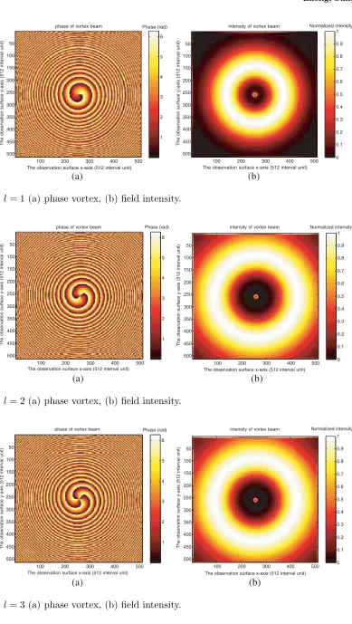
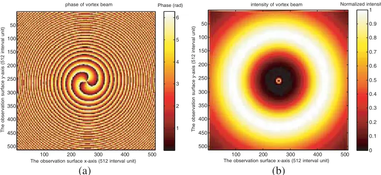
In the simulation, the parabolic antenna is divided into 200 parts alongϕ direction. According to the electromagnetic vortex wave formula, the results of phase structure, the vortex phase and amplitude of different modes (different topological charges) are calculated, as shown in Fig. 5 to Fig. 8.
phase of vortex beam
100 200 300 400 500 50 100 150 200 250 300 350 400 450 500 Phase (rad) 1 2 3 4 5 6
The observation surface x-axis (512 interval unit) 100 200 300 400 500 50 100 150 200 250 300 350 400 450 500 0 0.1 0.2 0.3 0.4 0.5 0.6 0.7 0.8 0.9 1 (a) (b)
The observation surface x-axis (512 interval unit)
The observation surface y-axis (512 interval unit) The observation surface y-axis (512 interval unit)
intensity of vortex beam Normalized intensity
Figure 5. l= 1 (a) phase vortex, (b) field intensity.
100 200 300 400 500 50 100 150 200 250 300 350 400 450 500 1 2 3 4 5 6
100 200 300 400 500 50 100 150 200 250 300 350 400 450 500 0 0.1 0.2 0.3 0.4 0.5 0.6 0.7 0.8 0.9 1 phase of vortex beam Phase (rad)
(a) (b)
The observation surface x-axis (512 interval unit)
The observation surface y-axis (512 interval unit)
intensity of vortex beam Normalized intensity
The observation surface y-axis (512 interval unit)
The observation surface x-axis (512 interval unit)
Figure 6. l= 2 (a) phase vortex, (b) field intensity.
100 200 300 400 500 50 100 150 200 250 300 350 400 450 500 1 2 3 4 5 6
100 200 300 400 500 50 100 150 200 250 300 350 400 450 500 0 0.1 0.2 0.3 0.4 0.5 0.6 0.7 0.8 0.9 1 phase of vortex beam Phase (rad)
(a) (b)
The observation surface x-axis (512 interval unit)
The observation surface y-axis (512 interval unit)
intensity of vortex beam Normalized intensity
The observation surface y-axis (512 interval unit)
The observation surface x-axis (512 interval unit)
100 200 300 400 500 50
100 150 200 250 300 350 400 450 500
1 2 3 4 5 6
100 200 300 400 500 50
100 150 200 250 300 350 400
450 500
0 0.1 0.2 0.3 0.4 0.5 0.6 0.7 0.8 0.9 1 phase of vortex beam Phase (rad)
(a) (b)
The observation surface x-axis (512 interval unit)
The observation surface y-axis (512 interval unit)
intensity of vortex beam Normalized intensity
The observation surface y-axis (512 interval unit)
The observation surface x-axis (512 interval unit)
Figure 8. l=−3 (a) phase vortex, (b) field intensity.
(a) (b)
Figure 9. Dielectric constant for (a) vertical polarization, (b) horizontal polarization.
has the properties that it is weak at the centre and strong around. It is obvious that the magnitude at the centre is much smaller than that at the surroundings, and the phase rotates around the centre with a 2π phase shift in one turn. So there exists a phase singularity at the centre of the beam, which indicates that the beam radiated by the proposed parabolic antenna carries with the OAM, and the clockwise and anti-clockwise phase distributions are around the centre of the phase singularity. From Fig. 7 and Fig. 8, it is observed that when the topological charges lare opposite numbers, the numbers of circular fringes are the same, but the rotations of the vortex waves are opposite, which indicates that the absolute value of topological charge has an influence on the number of circular fringes and electric field intensity, while different signs of topological charge will cause different rotations of equiphase surface. Due to the existence of phase singularity at the centre of the electric field, the electric field intensity is very small (less than 1) when the electric field is basically distributed in the plane of the measurement, and with the absolute value of topological charge increases, the electric field intensity at the same position on parabolic antenna is increased.
Figure 9(a) shows the graphs ofεandεchange with the azimuth angle ofϕin vertical polarization. We set the incident angleθi = 45◦. The solid line represents the real part, and the dotted line represents
(a) (b)
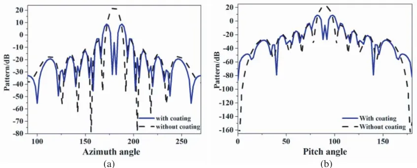
Figure 10. The simulated OAM radiation pattern: (a) horizontal polarization, (b) vertical polarization.
incident angle θi is also fixed as 45◦. Similar to Fig. 9(a), the solid line represents the real part, and
the dotted line represents the imaginary part. The graph shows that within a periodic, the real and imaginary parts are in the range of 0∼0.05. From Fig. 9, we can observe that the main polarization antenna is vertical polarization. The simulated results above verify that the method of generating vortex wave is feasible, and it is compatible with the conventional wireless electronic system to achieve efficient multiplexing and networking of vortex waves. The simulated radiation patterns of horizontal polarization and vertical polarization for OAM mode 2 at 6 GHz are shown in Fig. 10(a) and Fig. 10(b). It is clear that there are some low side lobe in the radiation pattern for mode 2.
4. CONCLUSION
A novel approach is proposed to generate electromagnetic vortex waves by coating specific controllable and complex dielectric constant material on the typical parabolic antenna. The simulated results verify that the proposed approach is simple and more efficient to generate electromagnetic vortex waves, and reduces the complexity of reflecting type vortex wave antenna. Due to the surface coating structure, it is convenient to conform to the existing antenna and other wireless electronic systems. Thus, it is very useful in the design of a high efficiency and multi-modes transmission device to achieve efficient multiplexing and networking of vortex waves for multi-users and multi-modes. In the near future, it may play a major role in practical vortex wave application.
ACKNOWLEDGMENT
This study was supported by the National Natural Science Foundation of China (No. 61372002). We thank for permission to work in National Key Laboratory of Antennas and Microwave Technology and Collaborative Innovation Centre of Information Sensing and Understanding, and was supported by the School of Physics and Optoelectronic Engineering, Xidian University.
REFERENCES
1. Wakayama, T., T. Higashiguchi, K. Sakaue, M. Washio, and Y. Otani, “Demonstration of a terahertz pure vector beam by tailoring geometric phase,” Scientific Reports, Vol. 8, 8690, 2018. 2. Wei, W., K. Mahdjoubi, C. Brousseau, and O. Emile, “Generation of OAM waves with circular
phase shifter and array of patch antennas,” Electronics Letters, Vol. 51, No. 6, 442–443, 2015. 3. Thid´e, B., H. Then, J. Sjoholm, K. Palmer, J. Bergman, T. D. Carozzi, Y. N. Istomin,
4. Mohammadi, S. M., L. K. S. Daldorff, J. E. S. Bergman, R. L. Karlsson, B. Thid´e, K. Forozesh, T. D. Carozzi, and B. Isham, “Orbital angular momentum in radio — A system study,” IEEE Transactions on Antennas and Propagation, Vol. 58, No. 2, 565–572, 2010.
5. Tamburini, F., B. Thid´e, G. Molina-Terriza, and G. Anzolin, “Twisting of light around rotating black holes,”Nature Physical, Vol. 7, No. 3, 195–197, 2010.
6. Cartlidge, E., “Adding a twist to radio technology,” Nature Medical, 2011.
7. Tamburini, F., E. Mari, A. Sponselli, B. Thid´e, A. Bianchini, and F. Romanato, “Encoding many channels in the same frequency through radio vorticity: First experimental test,” New Journal of Physics, Vol. 14, No. 11, 78001–78004, 2012.
8. Barbuto, M., F. Trotta, F. Bilotti, and A. Toscano, “Circular polarized patch antenna generating orbital angular momentum,”Progress In Electromagnetics Research, Vol. 148, 23–30, 2014. 9. Deng, C. J., W. H. Chen, Z. J. Zhang, Y. Li, and Z. H. Feng, “Generation of OAM radio waves
using circular Vivaldi antenna array,” Internation Journal of Antennas and Propagation, Vol. 2, 607–610, 2013.
10. Bai, Q., A. Tennant, B. Allen, and M. U. Rehan, “Generation of orbital angular momentum (OAM) radio beams with phased patch array,” Antennas & Propagation Conference, Loughborough, UK, 2014.
11. Spinello, F., E. Mari, M. Oldoni, R. A. Ravanelli, and C. G. Someda, “Experimental near field OAM-based communication with circular patch array,”Physics, 2015.
12. Wei, W. L., K. Mahdjoubi, C. Brousseau, and O. Emile, “Horn antenna for generating orbital angular momentum (OAM) waves,”Loughborough Antennas&Propagation Conference, 1420–1427, Loughborough, UK, 2016.
13. Shi, C. B., Y. B. Li, W. Wu, R. Y. Wu, and T. J. Cui, “An ultrathin spiral phase plate for generation of OAM radio waves,” Loughborough Antennas & Propagation Conference, Loughborough, UK, 2016.
14. Mao, F., M. Huang, T. Li, J. Zhang, and C. Yang, “Broadband generation of orbital angular momentum carrying beams in RF regimes,” Progress In Electromagnetics Research, Vol. 160, 19– 27, 2017.
15. Hui, X., et al., “Ultralow reflectivity spiral phase plate for generation of millimeter-wave OAM beam,” IEEE Antennas and Wireless Propagation Letters, Vol. 14, 966–969, 2015.
16. Cheng, L., W. Hong, and Z. C. Hao, “Design and implementation of planar reflection spiral phase plate for beams with orbital angular momentum,” IET Microwaves, Antennas & Propagation, Vol. 11, No. 2, 260–264, 2017.
17. Zhou, Z. Y., et al., “High efficiency SHG of orbital angular momentum light in an external cavity,” Physics, 2014.
18. Shi, B. S., et al., “Highly efficient second harmonic generation of a light carrying orbital angular momentum in an external cavity,”Optics Express, Vol. 22, No. 19, 23673–23678, 2014.
19. Yu, S. and L. Long, “New method for generating orbital angular momentum vortex beams in the radio frequency domain,” 2016 Progress In Electromagnetic Research Symposium (PIERS), 4121, Shanghai, China, Aug. 8–11, 2016.
20. Grekou, G., G. Dubost, and A. Madani, “Plane equiangular 4-ARM spiral antenna with conical reflector isolated or fitted into a structure,”European Microwave Conference, 2007.
21. Li, H., L. Kang, F. Wei, et al., “A low-profile polarized microstrip antenna array for dual-mode OAM applications,” IEEE Antennas and Wireless Propagation Letters, Vol. 16, 3022–3025, 2017.
22. Qin, F., J. Yi, et al., “A high-gain shared-aperture dual-band OAM antenna with parabolic reflector,”12th European Conference on Antennas and Propagation, 2018.