Abstract— this paper presents framework for developing shell expert system as new environment development for expert systems. The framework is based on the integration of two different knowledge representation formats. The integration consists of the Rule-base and the Case-based formats using the Blackboard. This scheme uses both procedural and declarative knowledge representation formalisms through the application of relational data base. So the rule base and case base formats have been converted into tables. In this paper all the algorithms, for creating, indexing, and checking the availability of a rule and a case, are present. The scheme facilitates combination of forward and backward chaining reasoning, using many problem solving methodologies, and different searching techniques. This view is based on the philosophy of human memory organization and utilization. Also individual uses the common sense, deduction and analogical reasoning activities in order to be more efficient for solving problems. Therefore, the proposed scheme facilitates the common sense, deduction and analogical reasoning activities in the inference engine, because rule base provides the deduction, case base provides the analogical reasoning, and the blackboard provides the common sense. The scheme makes the proposed Rule-Case-based shell expert system more flexible, efficient, and more powerful for the development of the expert systems in future. Index Terms — Computer Science, Artificial Intelligence, Expert Systems, Knowledge Engineering, and Information Technology.
I.INTRODUCTION
Expert systems are computer-based software applications which embody some non-algorithmic expertise for solving certain types of problems. Also the expert system can be defined as specific type of knowledge based system with the facilities of correctly deduct and making decision, in other words the knowledge based system that can answer the two questions How and Why. For example, expert systems are used in diagnostic applications servicing both people and machinery. They also play chess, make financial planning decisions, configure computers, monitor real time systems, underwrite insurance policies, and perform many other services which previously required human expertise [1].
Hussein H. Owaied is Associate Professor in the department of Computer Science, College of Information Technology.
Middle East University for graduate studies P.O.Box 42, Amman 11610, Jordan Phone: +9626 4790222 Fax: +9626 4129613 e-mail: [email protected]
Monzer Moh’d Qasem is a PhD. Student at The Arab Academy for Banking and Financial Sciences
College of Information Technology e-mail: [email protected]
There are many implementations of expert systems using various tools and various hardware platforms, from powerful LISP machine workstations to smaller personal computers. Many expert systems are built with products called shell expert systems [2]. The shell is a piece of software which contains the user interface, a format for representation of the knowledge base in narrow and specifics domains, and an inference engine. The knowledge engineer uses the shell to build an expert system for a particular problem domain. There continues to be a debate as to whether it is best to explore the technology and experiment for write expert systems or using shell expert systems [3]. One of the major bottlenecks in building expert systems is the knowledge engineering process. The coding of the expertise into the previously chosen format, such as rule base, frame, semantics nets, case-base, or others, can be a difficult and tedious task. The integration of (two or more) different knowledge representation methods is a very active research area in Artificial Intelligence. The aim is creates hybrid formalisms benefiting from each of their components. It is generally believed that complex problems can be easier solved with hybrid systems. The effectiveness of the various hybrid approaches has been demonstrated in a number of application areas [4]. In most of the hybrid approaches, two knowledge representation methods are being integrated. This is due to the fact that the integration of three or more knowledge representation methods is more complicated. One of the most popular types of integration involves the combination of rule-based with case-based reasoning approaches [5]-[6]. The efforts to combine symbolic rules and cases have yielded advanced knowledge representation formalisms. The effectiveness of those approaches stems from the fact that rules and cases are alternatives in representing application domains and solving problems [7]-[9]. Rules represent general knowledge of the domain, whereas cases specific knowledge. Rule-based systems solve problems from scratch, while case-based systems use previously stored situations to deal with similar new instances, therefore, the integration of both approaches turns out to be natural and useful [10].
II.STRUCTURE OF SHELL EXPERT SYSTEM
The shell expert system is a complete development environment for building and maintaining knowledge-Based Applications and Expert Systems. It provides a step-by-step methodology for a knowledge engineer that allows the domain experts themselves to be directly involved in structuring and encoding the knowledge [11].
Developing Rule-Case-Based Shell Expert
System
Most expert systems are developed via specialized software tools called shell expert systems. These shells come equipped with an inference mechanism (backward chaining, forward chaining, or both), and require knowledge to be entered according to a specified format, user interface, explanation facilities and editing facilities as seen in Fig. 1.
Fig. 1 Architecture of Rule-Case-Based Shell Expert System
A.The Proposed Knowledge Base Scheme (Format)
The knowledge base represents the repository of knowledge for specific and narrow domain for the knowledge based system. So, the most important part of knowledge based system is the knowledge base and the power of any knowledge based system and Expert System inherently in the adequate and integration of knowledge representation forms used for the particular domain. In this sense, the most important phase, in building knowledge based system and the expert systems, is the building of the knowledge base; this process is part of knowledge engineering which is an important field at present century. Usually, expert systems are designed and implemented for dedicated narrow and specific domain, while sell expert system can be used for developing expert system in any domain, but shell expert system are also governed by the format used for representation of the knowledge base. The proposed scheme consists of the Rule-base and the Case-based formats using the Blackboard. The scheme facilitates combination of forward and backward chaining reasoning, using many problem solving methodologies, and different searching techniques. The scheme makes the proposed Rule-Case-based shell expert system more flexible, efficient, and more powerful for the development of the expert systems in future. This view is based on the philosophy of human memory organization and utilizing for solving problems. Usually human uses more than one form for knowledge representation in his long term memory in order to be more efficient for solving problems, also the knowledge of any
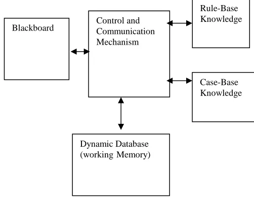
domain can’t be in one format. In the literature survey, found that many publications have covered the development of knowledge-based systems into expert system, using case-based reasoning in the areas of conceptual design, aircraft conflict resolution, military decision support systems, help-desk operations, customer service management, legal systems, diagnosis, design, and planning [12]-[ 14]. It is seen that the applications of Case-Based Reasoning in developing knowledge-based systems and the expert systems have been widely adopted in various industries and other application areas [15]. Furthermore some applications have been incorporate other knowledge representation methods besides rule-based and case-based reasoning, such as neural networks and fuzzy logic [16]. Combination of forward chaining reasoning and backward chaining reasoning makes expert systems more flexible and efficient and also the use of more than one knowledge representation forms makes the expert system more powerful. Therefore, the mixing of rule-base and the Case-rule-based forms using Blackboard has not been used before for the shell expert systems. The proposed scheme facilitates the common sense, deduction and analogical reasoning activities in the inference engine, because rule base provides the deduction, case base provides the analogical reasoning, and the blackboard provides the common sense, as seen in Fig. 2 [17].
[image:2.595.46.290.150.323.2]
Fig. 2 the Architecture of Hybrid Knowledge Scheme
B.User Interface
The user interface simulates the communications facilities available to be used for interaction with the Rule-Case-Based shell expert system. This means an information processing system of one of (vision, speech, hearing, touching, tasting) or specified protocol many be used to connect the shell expert system to another computerized system.
User Interface
Inference Engine
Knowledge Base Scheme (formats)
Explanation Facilities for correctly deduction and decision making Editing
Facilities for create and update the knowledge base
Dynamic Database (workingMemory)
Rule-Base Knowledge Control and
Communication Mechanism
[image:2.595.311.562.377.574.2]Usually the chosen method or methods to interact with the shell expert system will be based on format used for the representation of knowledge in the knowledge base. Since, the formats used in the proposed system will be a scheme of the integration of two formats, which are rule-base and case-base, so the user interface will be the appropriate communication facilities between the proposed Rule-Case-Based shell expert system and the domain expert peoples. These facilities allow the user (the domain expert peoples) to create and update the knowledge-base during the development of the expert system. But if the proposed Rule-Case-Based shell expert system connected to a computerized knowledge acquisition system then the interaction between two computer-based systems will be through the special protocols between them and should be appropriate with the proposed scheme for representation of the knowledge base.
C.The Inference Engine
The inference engine was playing the most important role in the construction of functional model of human system as mentioned in [18]. But its implementation depends on the representation of knowledge in the knowledge base of the shell expert system. Therefore, the implementation of the inference engine will be regarded as a combination of problem solving method, reasoning agent and search technique. Unfortunately, it is difficult to implement general problem solving method for any field, or a general search technique for any field also. The reasoning agent is responsible to accept sophisticated queries concerning general knowledge to deduct specific knowledge in order to use by the problem solving method and the searching technique. The power of the solver reasoning agent can be increased by implementing a larger number of solvers and by enhancing their capabilities to solve complex tasks. The use of case base format will be facilitates the analogical reasoning and the use of rule base format will facilitates the deduction during the process of solving a problem. The use of blackboard and dynamic memory together with analogical reasoning will a simulation of the common sense of human beings. Therefore the inference engine is a simulation of human behavior for solving a problem using the activities of deduction, analogical reasoning and common sense.
III.IMPLEMENTATION OF THE PROPOSED SCHEME In reality, usually human have two types of knowledge which are Procedural and Declarative, so the proposed scheme will use both types of knowledge, which are the Rule base presents as Procedural and Case based presents as declarative. The following subsections present the detail description for the implementation of the proposed scheme. The description present the methodologies used for creating, retrieving, and updating of both Rule-base and Case-base.
A.The Rule Base
In this project the relational database will be used to represent the rule as table. The rules will be stored in a table format with the maximum of number of column are k, for example if k=6, then (Col-1, Col-2 … Col-6), as shown in table 1. The first column represents the left-hand-side of the rule, which is the conclusion of a rule usually called action (A) and from column-2 to column-6 are used to represent the conditions of the rule (C1, C2… C5), so this rule will be as Horn clause presented as follows:
A C1, C2, C3, C4, C5
Table-1 presents layout of a rule in the table
Col-1 Col-2 Col-3 Col-4 Col-5 Col-6
A C1 C2 C3 C4 C5
In this view assume that any rule has maximum conditions are 5, but if a rule has more conditions, then the sixth column will be sub-action which has the reset of the conditions and so on. In this case the representation of knowledge is procedural representation not declarative representation. Some examples will show how the conditions are going to be stored in the table depend on the number of conditions.
B.Creating Table
The following Fig. 3, Fig. 4.a and, Fig. 4.b present the flowchart and pseudo code respectively used to create table with 6 columns and to check the availability of a rule in the table or not before saving it, which means checking the Action of a rule and its Conditions.
[image:3.595.316.551.504.736.2]10 CREATE MATRIX (NUMBER OF ROWS, 6) 20 INITILIZE I TO ZERO
30 INITILIZE NUMBER OF COLOUMN TO ZERO
40 INPUT THE ACTION NAME GO TO AVALIABILITY ALGORITHM
60 IF THE AVALIABILITY IS EQUAL TO TRUE 70 GO TO 40
80 ELSE
90 SAVE ACTION NAME TO TABLE 100 SET NUMBER OF COLUMN IS EQUAL TO NUMBER OF COLUMN PLUS ONE
110 INPUT THE NUMBER OF CONDITION 120 IF NUMBER OF CONDITIONS IS LESS THAN OR EQUAL TO FIVE
130 GO TO CONDITION ALGORITHM
140 ELSE GO TO FURMULA ALGORITHM SET VALUE TO J IS EQUAL TO NUMBER OF ROWS
170 INITILIZE I TO ZERO
180 INITILIZE NUMBER OF COLUMN TO ONE 190 GO TO CONDITION ALGORITHM 200 IF NUMBER OF COLUMN IS EQUAL TO FIVE
210 SAVE ACTION NAME CONCATONATE WITH NUMBER OF ROWS
220 SET NUMBER OF COLUMN IS EQUAL TO ZERO
230 SAVE ACTION NAME CONCATONATE WITH NUMBER OF ROWS
240 SET NUMBER OF COLUMN IS EQUAL TO ONE
250 NUMBER OF ROWS IS EQUAL TO NUMBER OF ROWS MINUS ONE GO TO CONDITION ALGORITHM
270 ELSE GO TO CONDITIN ALGORITHM Fig. 4.a presents the pseudo code for creating table
10 INPUT THE CONDITION VALUE 20 GO TO CHECK AVALIABILITY ALGORITHM
30 IF AVALIABILITY IS EQUAL TO TRUE 40 GO TO 10
50 ELSE SAVE CONDITION VALUE IN TABLE
70 SET I IS EQUAL TO I PLUS ONE
80 SET NUMBER OF COLUMN IS EQUAL TO NUMBER OF COLUMN PLUS ONE 90 IF I IS EQUAL TO NUMBER OF COLUMN 100 EXIT
[image:4.595.52.329.36.723.2]110 ELSE GO TO 10
Fig. 4.b presents the pseudo code for creating table
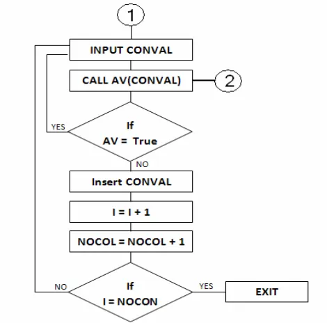
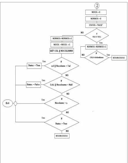
C.Checking Availability of a Rule
The following Fig. 5 and Fig. 6 present the pseudo code and flowchart respectively used to check the availability of a rule in the table or not before saving it, which means checking the Action of a rule and its Conditions.
10 INITILIZE NUMBER OF COLOUMN TO ZERO 20 INITILIZE NUMBER OF ROWS TO ZERO 30 SET STATUS IS EQUAL TO "FALSE" 40 IF VALUE IS NULL
50 SET NUMBER OF ROWS IS EQUAL TO NUMBER OF ROWS PLUS ONE
60 IF COLUMN1 IS EQUAL TO ACTION NAME 70 SET STATUS TO TRUE
80 ELSE GO TO 50
100 ELSE SET NUMBER OF ROWS IS EQUAL TO NUMBER OF ROWS PLUS ONE
120 SET NUMBER OF COLOUMN IS EQUAL TO NUMBER OF COLOUMN PLUS ONE 130 GET COLUMN CONCATONATE WITH NUMBER OF COLUMNS
140 IF COLUMN CONCATONATE WITH NUMBER
OF COLUMNS IS EQUAL TO VALUE 150 STATUS IS EQUAL TO TRUE
160 EXIT 170 ELSE
180 IF COLUMN CONCATONATE WITH
NUMBER OF COLUMNS IS EQUAL TO NULL 190 STATUS IS EQUAL TO FALSE
200 EXIT 210 ELSE
220 IF NUMBER OF COLUMNS IS EQUAL TO SIX
230 EXIT 240 ELSE
250 IF STATUS IS EQUAL TO TRUE 260 EXIT
270 ELSE
280 SET STATUS TO TRUE
[image:4.595.299.553.138.596.2]
[image:5.595.54.496.67.626.2]
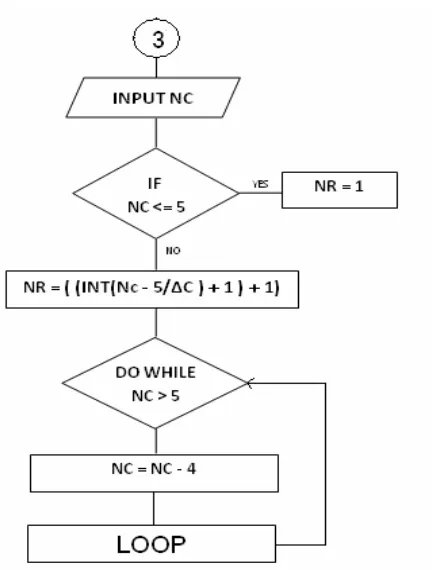
D.Algorithm of Calculating Number of Rows
The following formula is used to determine the number of rows required for a particular rule according to the number of conditions in the rule.
Where: Nc is Number of conditions
∆c: the difference between the conditions to be stored in each row, its value 4 because the table contains 6 columns and the maximum conditions to be stored is 5.
Fig. 7 and Fig. 8 below present the flowchart and pseudo code respectively. They are used to calculate the number of rows, for store a particular rule in the table, according to the number of conditions.
Fig, 7: presents the flowchart used to calculate the number of rows
10 INPUT THE NUMBER OF CONDITIONS 20 IF NUMBER OF CONDITIONS IS LESS THAN OR EQUAL TO 5
30 SET NUMBER OF ROWS IS EQUAL TO ONE 40 ELSE
50 SET NUMBER OF ROWS IS EQUAL TO INITIAL (NUMBER OF
COLUMNS-5/∆C)+1)+1)
60 WHILE NUMBER OF COLUMNS IS GREATER THAN FIVE
[image:6.595.308.552.51.199.2]70 SET NUMBER OF COLUMNS IS EQUAL TO NUMBER OF COLUMNSMINUS FOUR Fig. 8: The pseudo code for calculate the number of rows
E.The Representation of General Form of a Rule
[image:6.595.20.212.119.195.2]The following is the procedure for representing a rule in a table using the algorithm for calculating the number of rows required according to the number of conditions of the rule.
1) Applying the algorithm for calculate number of rows, n.
[image:6.595.47.263.367.652.2]2) If n<=5, then the representation as shown in table 2.
Table-2: The layout of the rule with conditions <= 5
Col-1 Col-2 Col-3 Col-4 Col-5 Col-6
A C1 C2 C3 C4 C5
3) If n>5, then the representation as shown in table 3.
Table-3: The layout of the general form of a rule
Col-1 Col-2 Col-3 Col-4 Col-5 Col-6
A C1 C2 C3 C4 Anumber of
rows-1
Anumber of rows-1 C5 C6 C7 C8 Anumber of rows-2
Anumber of rows-2 C9 C10 C11 C12 Anumber of rows-3
Anumber of rows-3 C13 C14 C15 C16 Anumber of rows-4
F.Illustration Examples for Rule Base
The following are three examples, which are demonstrating the layout of the rules.
Example (1):
Pregnancy Missed one male, Nausea,
Generalized weakness, Pregnancy test positive 5
>
5 <= +
+
∆ −
=
:NcNc : 1 1 5
1 C Nc
Table-4: The layout of the rule in example (1)
Cl-1 Cl-2 Cl-3 Cl-4 Cl-5
Preg nanc y
Missed one male
Nausea Generalized weakness
pregnancy test positive
The example in table 4, shows that the numbers of conditions are four which are stored in columns from Col-2 to Col-5 and the Col-6 not used, the action will be stored in Col-1.
Example (2):
Sinusitis Headache, Itching in nose, Sneezing, Watering of eyes, X-Ray show dizziness in the sinus
Table-5: The layout of the rule in example (2)
Col-1 Col-2 Col-3 Col-4
Col-5
Col-6 Sinusitis Headache Itching
in nose
Sneezing watering of eyes
x-ray show
dizziness in the
sinus
The example in table 5, shows that the numbers of conditions are five which are stored in columns from Col-2 to Col-6 means that all the columns in the table being engaged. The action will be stored in Col-1.
Example (3):
Tonsillitis Fever,
Generalized fetid, Pain in throat,
On examination redness,
Follicular, Some time pus Table-6: The layout of the rule in example (3)
Col-1 Col-2 Col-3 Col-4
Col-5 Col-6 Tonsillit
is
Fever generaliz ed fetid
pain in throat
On examine redness
Tonsilitis1
Tonsiliti s1
Follicula r
some time pus
The example in table 6 shows that the numbers to conditions are six, which are exceeding the numbers of columns, are allocated to store the conditions.
So the four conditions of the rule stored in Col-2, Col-3, Col-4, Col-5 and the head of the rule is stored in Col-1 and pretend that sub-action as a condition and store the sixth condition of the rule in Col-6 which has the same name of the head together with the index, in this example the index is 1. After that store the pretended condition in a new row as a new action and continue store the remaining conditions that have numbers five and six.
That is A C1, C2, C3, C4 ,A1
A1 C5, C6
Note that:
If we have a number of eleven conditions, the solution is A C1, C2, C3, C4, A1 A1 C5, C6, C7, C8, A2 A2 C9, C10, C11
G.Case Base
Usually, the human experiences for solving problems in a certain domain present the collections of cases; each case presents a problem and its solution. Organizing the storage of the cases and retrieval of cases is central for effective case-based reasoning method. Cases can be organized by the goal and retrieved when the case has the same goal as the current situation. Another organizing method is to use cases with most important features matched or the most number of features matched. The matching may first look for exactly matched case before looking for a more general case. Using the cases most frequently matched or most recently matched is also used when retrieving cases to match a new situation. Another method is to use the case that matches without much adjusting. Using these heuristics a similar case is retrieved.
Fig. 9 presents the relationships between tables
Table-7: The relationships between tables
Table (1) To Table (3) One – To – Many Table (2) To Table (3) One – To – Many Table (1) To Table (2) One – To – Many
Table-8: The keys types used for tables
Table (1) The Column (Case_Number) is Primary key Table (2) The Column (Condition_Number) is Primary key
Table (3) The Columns (Case_Number,
Condition_Number) is Primary key
Table (3) The Column (Case_Number) is foreign key Table (3) The Columns (Condition_Number) is foreign key
10 CREATE TABLE NAME CASES WITH TWO FIELDS 10.1 FIELD NAME: CASE_NO AND FIELD TYPE: NUMBER(4) 10.2 FIELD NAME: CASE_NAME AND FIELD TYPE:
VARCHAR2(100) NOT NULL
10.3 CREATE UNIQUE INDEX CASES_BRW_P1 ON CASES TABLE BY FIELD (CASE_NO) 10.4 CREATE PRIMARY KEY ON TABLE CASES USING FIELD CASE_NO ALTER TABLE CASES ADD ( CONSTRAINTCASES_BRW_P1 PRIMARY KEY (CASE_NO));
20 CREATE TABLE NAME CONDITIONS WITH TWO FIELDS
20.1 FIELD NAME: CONDITION_NO AND FIELD TYPE: NUMBER(4)
20.2 FIELD NAME: CONDITION_NAME AND FIELD TYPE: VARCHAR2(100) NOT NULL 20.3 TO MAKE RELATION FROM TABLE(1) TO TABLE(2) USING FIELD NAME: CASE_NO NUMBER(4)
20.4 CREATE UNIQUE INDEX
CONDITIONS_BRW_P1 ON CONDITIONS TABLE BY FIELD (CONDITION_NO) 20.5 CREATE PRIMARY KEY ON TABLE
CONDITIONS USING FIELD CONDITION_NO ALTER TABLE CONDITIONS ADD
(CONSTRAINT CONDITIONS_BRW_P1 PRIMARY KEY (CONDITION_NO)); 20.6 CREATE FOREIGN KEY ON TABLE CONDITIONS USING FIELD CASE_NO ALTER TABLE CONDITIONS ADD (CONSTRAINT CONDITIONS_BRW_F1 FOREIGN KEY (CASE_NO) REFERENCES CASES (CASE_NO));
30 CREATE TABLE NAME CASES_CONDITIONS WITH TWO FIELDS
30.1 FIELD NAME: CASE_NO AND FIELD TYPE: NUMBER(4) NOT NUL
30.2 FIELD NAME: CONDITIONS_NO AND FIELD TYPE: NUMBER(4) NOT NULL
30.3 CREATE UNIQUE INDEX
CASES_CONDITIONS_BRW_P1 ON CASES_CONDITIONS TABLE BY FIELD (CASE_NO, CONDITIONS_NO)
30.4 CREATE PRIMARY KEY ON TABLE CASES_CONDITIONS USING FIELDS CASE_NO, CONDITIONS_NO ALTER TABLE CASES_CONDITIONS ADD (CONSTRAINT CASES_CONDITIONS_BRW_P1 PRIMARY KEY (CASE_NO, CONDITIONS_NO)); 30.5 CREATE FOREIGN KEY ON TABLE CASES_CONDITIONS USING FIELD CASE_NO ALTER TABLE
CASES_CONDITIONS ADD (CONSTRAINT CASES_CONDITIONS_BRW_F1 FOREIGN KEY (CASE_NO) REFERENCES CASES (CASE_NO));
30.6 CREATE FOREIGN KEY ON TABLE
CASES_CONDITIONS USING FIELD CONDITIONS_NO ALTER TABLE CASES_CONDITIONS ADD
(CONSTRAINT CASES_CONDITIONS_BRW_F2 FOREIGN KEY (CONDITIONS_NO) REFERENCES CONDITIONS (CONDITION_NO));
[image:8.595.27.271.54.306.2]H.Illustration Examples for Case Base
In the following examples, there are ten cases which are stored in the column two of the table-9, while the first column stores the index numbers for the cases as shown below, each case contains a number of conditions depend on the case given which stored in the second column of the table-10 also the first column of the table-10 shows the index number for the conditions, so the total cases are ten and the total conditions are 54 given. By using the relation called One–To–Many between the tables; it will be produce a new table contains two columns: the first column called Case_Number which is refers to the index number for the cases and the second column called Condition_Number which is refers to the index number for the conditions as shows in table-11. From table-11, it's observed that the number of cases remains as it is while the number for conditions reduced to 43 instead of 54 without deleting any condition, i.e. 9 conditions are repeated in several cases which is not included in table-11. Thus the main advantages of this methodology is to avoid duplication in conditions, flexibility of marinating tables and easy for searching.
Table-9: CASES
Table-10: CONDITIONS
Condition_Number Condition_Name
1 MISSED ONE MENS
2 NEUSEA
3 GENRALIZED WEEKNESS
4 PREG. TEST POSITIVE
5 HEADECH
6 VOMITTING
7 ITCHING IN NOSE
8 SNEEZING
9 WATERING OF EYES
10 X-RAY SHOW HIZZINESS IN THE SINUS
11 FEVER
12 PAIN IN EAR
13 DISCHARGE FROM EAR
14 REDNESS IN TEMPANIC
MEMBRAN AND CANAL
15 PAIN IN ANAL AREA
16 CONSTIPATION
17 ITCHING
18 DISCHARGE
19 BLEEDING
20 REDNESS
21 TENDERNESS
22 DISCHARGE FROM EYES
23 PAIN IN TESTIS
24 HOTNESS
25 SWELLING
26 SOME TIME REDNESS
27 ABDOMENAL PAIN
28 EXAMINATION TENDERNESS ALL OVER ABDOMEN
29 DECREASED OR ABSENT
BOWAL SOUND
30 X-RAY SHOW MULTIPLE
FLOUD LEVEL
31 BLOOD TEST ELECTROLIT ABNORMALATIES
32 COGHT
33 DEFICULTY OF BREATH
34 CHEST X-RAY SHOW
ABNORMALATY
35 PAIN
36 GENERALIZED FETIQ
37 PAIN IN THROT
38 ON EXAMINATION REDNESS
39 FOLICULAR
40 SOME TIME PUS
41 COLLECTION OF PUS
42 HARDNESS
43 EXAMINATION OF THE AREA THERE IS FLUCTUATION
Table-11: CASES_CONDITION
Case_Number Condition_Number
1 1
1 2
1 3
1 4
1 5
1 6
2 5
2 7
2 8
2 9
2 10
3 11
3 12
3 13
3 14
4 15
4 16
4 17
4 18
4 19
Case_N umber
Case_Name
1 PREGNACY
2 SINUSITIS
3 OTITIS MEDIA
4 HEMERROID
5 ACUTE COJUCTIVITIS
6 EPIDIDEMOORCHITIS
7 INTESTINSL OBSTRUCTION
8 UPER RESPIRATORY TRACT
INFECTION
9 TONSILITIS
5 20
5 17
5 21
5 9
5 22
5 5
6 23
6 24
6 25
6 26
7 6
7 27
7 28
7 29
7 30
7 31
8 32
8 33
8 11
8 34
8 35
9 11
9 36
9 37
9 38
9 39
9 40
10 35
10 41
10 20
10 43
10 21
10 24
I.The Blackboard
The blackboard is a shared repository of problems, goals, partial solutions, suggestions and contributed information. The blackboard can be viewed as a dynamic library of requests and contributions that have been recently provided through the cooperation mechanism between the rule base knowledge and the case base knowledge. In a case-based, a problem is matched against cases in the case base, and one or more similar cases are retrieved. Case indexing involves assigning indices to cases to facilitate their retrieval. In order to decide whether or not there is a similar case to retrieve for further processes, witch means check the availability of case to retrieve as a condition or checking the Rule-base. In order to retrieve cases efficiently, it is crucial to decide what the key attributes of a case are and on which attributes the cases should be indexed, see table-8. All these processes will be done in the Blackboard.
A solution suggested by the matching cases is then reused. Unless the retrieved case is a close match, the solution will probably have to be revised, producing a new case that can be retained. The following Fig. 11 and fig. 12 present the flowchart and pseudo code respectively used for processing user query.
Fig.12 The pseudo code for processes using user query
J.Control and Cooperation Mechanisms
The control mechanism is to control and reorganize the knowledge bases and used them in the most effective and coherent fashion. The cooperation mechanism is the activities of passing the appropriate part of knowledge from one knowledge base to another and converting from one representation form into another. Control and cooperation mechanisms make use of the dynamic data base, the knowledge bases (Rule base and Case base) and the blackboard in order to decide whether there is a similar case to retrieve for further processes or not. This means check the availability of case to retrieve as a condition in a particular rule or checking the rule base to find a particular rule to apply. All these processes have been done in the Blackboard.
REFERENCES
[1] George F Luger. Artificial Intelligence Structures and Strategies for Complex Problem Solving. Addision Wesley, fifth edition, 2005.
[2] Carol E. Brown "Introduction to Artificial Intelligence and Expert Systems", Oregon State University 1993, 1994, 1995.
[3] MD Salim, Alvaro Villavicencio, & Marc A. "A Method for Evaluating Expert System Shells for Classroom Instruction" Timmerman, Journal of Industrial Technology, Volume 19, Number 1 November 2002 to January 2003.
[4] Hany I. Fahmy and Christos Douligeris, "Applications of Hybrid Fuzzy Expert Systems in Computer Networks Design ", Dept. of Electrical and Computer Engineering, University of Miami 1999.
[5] D. Aha and J.J. Daniels (eds.), “Case-Based Reasoning Integrations: Papers from the 1998 AAAI Workshop”. Technical Report WS-98-15, AAAI Press, 1998.
[6] G. Vossos, J. Zeleznikow, Th. Dillon, and V. Vossos, “An Example of Integrating Legal Case- Based Reasoning with Object-Oriented Rule Based Systems: IKBALS II”, in Proc. 1991 International Conference on Artificial Intelligence and Law, pp. 31-41.
[7] Jim Prentzas, Ioannis Hatzilygeroudis."Integrations of Rule-Based and Case-Based Reasoning", Dept. of Computer Engine. & Informatics, University of Patras, 26500 Patras, Hellas (Greece) & Research Academic Computer Technology Institute, Patras, Hellas (Greece), S. Craw and A. Preece (Eds.): ECCBR 2002, LNAI 2416, pp. 336–349,
Springer-Verlag Berlin Heidelberg 2002
[8] Aamodt, A. & Plaza, "Case-Based Reasoning: Foundational Issues, Methodological Variations, and System Approaches". AI Communications, 7(i): pp 39-59 E. (1994).
[9] J. Sabater, J.L. Arcos, and R. Lopez de Mantaras, “Using Rules to Support Case-Based Reasoning for Harmonizing Melodies”, in [12], pp. 147-151
[10] Robert Chi and Melody Kiang. "An integrated approach of rule-based and case-based reasoning for decision support." ACM Annual Computer Science Conference Proceedings of the 19th annual conference on Computer Science, pages 255–267, 1991.
[11] Chan C.W., Chen L.L., Geng L., ‘Knowledge Engineering of an intelligent case-based system for helpdesk Operations", Expert Systems with Applications, Vol. 18, No.2, PP 125-132, 2000.
[12] R. Bellazzi, S. Montani, L. Portinale and A. Riva, “Integrating Rule Based and Case-Based Decision Making in Diabetic Patient Management” in Proc. 1999 International Conference on Case-Based Reasoning, pp. 386-400.
[13] A.K.Sharma, Chander Kumar, Khurram Mustafa, Ashok Kumar, "A Fuzzy Frame Based Expert Shell", Proceedings: National Workshop on IT Services and Applications (WITSA2003) Feb 27-28, 2003
[14] Aref, MM; AlMuhtaseb, HA, Khabeer: "An Object-Oriented Arabic Expert System Shell", Arabian Journal for Science and Engineering; pp: 275-293; Vol: 22, 1997 King Fahd University of Petroleum & Minerals
[15] P. Smith, O. Taylor, J. MacIntyre and J.I. Tait, “Expert System Applications: Power Industry” in the Handbook of Expert Systems” Ed. J Lebowitz, CRC Press. 1998.
[16] Lawrence O. Hall Rule Chaining in Fuzzy Expert Systems This paper appears in: Fuzzy Systems, IEEE Transactions on
Publication Date: Dec 2001 Volume: 9, Issue: 6, pp 822-828
[17] Hussein H. Owaied, Monzer Moh’d Qasem Hybrid Knowledge representation scheme for expert system, International Conference on Artificial Intelligence (ICAI 2008) Volume II, July 14-17, 2008. Las Vegas Nevada, USA.
[18] Hussein H. Owaied, Abu-Arr’a M. Mahmoud: "Functional Model of Human System as knowledge Base System", The 2007 International Conference on Information & Knowledge, Engineering, June 25-28 2007, pp158-161.
10 INPUT NUMBER OF CONDITIONS
20 INITILIZE I TO ZERO 30 INPUT THE CONDITION
40 SET CONDITION OF I IS EQUAL TO CONDITION 50 GO TO CHECK AVALIABILITY ALGORITHM 60 IF THE AVALIABILITY IS EQUAL TO TRUE 70 SET CONDITION1 IS EQUAL TO CONDITION 80 SET A1 IS EQUAL TO A1 PLUS CONDITION OF I 90 ELSE
100 SET CONDITION0 IS EQUAL TO CONDITION 110 SET A0 IS EQUAL TO A0 PLUS CONDITION OF I 120 IF I IS EQUAL TO NUMBER OF CONDITIONS 130 IF CONDITION1 IS EQUAL TO NUMBER OF CONDITIONS RETRIEVE ACTION
150 ELSE IF CONDITION1 IS GREATER THAN OR EQUAL TO CONDITION
170 SET SIMILAR ACTION IS EQUAL TO A1 180 SET NEW CONDITION IS EQUAL TO SIMILAR ACTION CONCATONATE WITH A0 GO TO CHECK
AVALIABILITY ALGORITHM FOR NEW CONDITION