Collaborative Development of System Architecture - a Tool for Coping with
Inconsistency
Peter Henderson
Electronics and Computer Science
University of Southampton
SO17 1BJ, UK
[email protected]
Matthew J. Henderson
Mathematics and Computer Science
Berea College
Berea, KY 40404, USA
matthew [email protected]
Abstract
Very large systems have an architecture that is designed to allow them to evolve through a long life. Such systems are developed by teams of architects. One of thefirst things the architects do is make a model of their architecture. This model constitutes the formal architecture description based on which software engineers will eventually build the real system.
The architecture model is normally governed by a spe-cialised metamodel whose rules determine the consistency and completeness of the description. The development of a system architecture is carried out cooperatively but inde-pendently by team members. Consequently it is quite nor-mal for the architecture description as a whole to be both incomplete and inconsistent. The architects strive to even-tually produce a complete overall (i.e. merged) description and to eliminate the inconsistencies.
By means of an example, we show how and why the ar-chitecture model and the metamodel must co-evolve. We de-scribe a design tool that we have developed to support this process of co-evolution. The tool allows a team of architects to detect inconsistencies in their separate and merged mod-els. The tool tolerates inconsistencies. It produces reports of inconsistencies which then become targets for removal as the whole architecture description evolves.
1. Introduction
Very large systems have an architecture that is designed to allow them to evolve through a long life. The usual way in which such large systems are developed is byfirst mak-ing a model of their architecture. The language chosen for the architecture model is usually a mixture of diagrams (in UML or SysML, for example) and lots of documentation of requirements and of interfaces to the components that are to
be either procured or built. The model is thus a semi-formal architecture description.
The architecture is normally developed incrementally and independently by a team of system architects working collaboratively. While each may strive to keep their part-model of the evolving architecture consistent, there will be inconsistencies between their independent descriptions. These inconsistencies will need to be detected and resolved when, from time to time, the models of independent archi-tects are merged.
The more formal the architecture description, the more likely we are to be able to determine incompletenesses and inconsistencies at an early stage. A formal architecture model is governed by a specialised metamodel whose rules determine the consistency and completeness of the descrip-tion. During development of a system, it is quite normal for the architecture description to be both incomplete and inconsistent. The architects strive to produce a complete description and to eliminate the inconsistencies.
We describe a method of formalising the rules for the development of a new architecture, in a metamodel that the architects team can agree on, and which can co-evolve with the architecture description itself.
By means of an example, we show how architecture de-scriptions formalised in this way can aid the iterative pro-cess of architecture development and how the model and the specialised metamodel can co-evolve.
We then describe a design-support tool, WAVE, that we have developed to support this process of co-evolution. This tool will calculate inconsistencies within individual and merged models. It does not insist on the architecture model always being consistent. Rather it produces reports of inconsistencies. These inconsistencies are targets for the architects to eventually remove. This means of tolerating inconsistency supports both incremental and collaborative working, essential to the development of large systems by teams of engineers.
2. Background
System Architecture is an essential aspect of the design of large system. It forms the overall structure within which the components of the system interact with each other [19, 20, 23, 29] and consequently the basis on which architects negotiate with each other about how the system as a whole will eventually work.
There have been many approaches to the description of System Architecture, both formal and semi-formal. We have been influenced by both, but in particular the more pragmatic methods [1, 16, 17, 18], in particular those that combine familiar semi-formal methods with an element of evaluation [5, 10, 28, 30].
We are particularly concerned with methods that scale up to be applicable to very large systems [2, 12, 14, 20, 22], by which we mean those that will eventually require a large team of software engineers working over an extended period of time. Such methods necessarily involve a great degree of collaboration [8, 21, 25].
Large systems and collaborative development include long periods when the design is both incomplete and in-consistent. The inconsistencies arise when separate parts of the architecture description are developed independently. Many others have worked on the issue of ensuring consis-tency [6, 9, 26, 27], while others have addressed the issue of tolerating inconsistency [2, 22]. This work has been funda-mental in our development of the method and tool that we propose here.
We have also been influenced in the development of our tool, by the tools developed by others, in particular those based on a relational model of architecture [3, 4, 11, 17]. The relational algebra [7, 17, 18] is an ideal formal language for giving structural architecture descriptions and goes a long way towards being appropriate for behavioural de-scriptions. This, we believe, is because at the level at which architecture description needs to be performed (sufficiently detailed but appropriately abstract) a relational model intro-duces just the right level of formality. Note that UML (and SysML) have metamodels which are described relationally. This perhaps explains why relational models are a goodfit to the task of architecture description.
In the discussion at the end of the paper we mention ad-ditional areas of application, including documentation [15] and modular reasoning [24, 13], both of which require ar-chitectural support. Butfirst, we illustrate our method using familiar examples from software engineering.
3. A Method of Architecture Description
System Architects, building software intensive systems, start from a mixture of user requirements, system require-ments and legacy components and devise an architecture
1. The architects agree a preliminary metamodel,including entities, relationships and consistency rules.
2. Each architect develops their part of the model,obeying as nearly as possible the current meta-model.
3. Each architect strives to drive out inconsistenciesin their part of the model. 4. Periodically, models are merged so that
cross-model inconsistencies can be eliminated.
5. Periodically, the metamodel is evolved to encodethe architects’ evolving understanding of the prob-lem domain.
Table 1. Architecture Development Method
that meets the requirements while making effective use of existing components. They will describe the architecture using a mixture of diagrams and natural language that is ef-fective as a means of communication among them and their customers
Diagrams are most effective at indexing a description. The reader uses the diagrams to get an overview of the (part of the) architecture in which they are interested and then refers to a natural language description to learn the details. The reader will expect to find redundancy in the descrip-tions and consistency between related parts. For example, in the next section you will see (Figures 2 and 3) diagrams that exhibit redundancy and consistency - in this case, a class di-agram and an apparently consistent sequence didi-agram .
An essential adjunct to the diagrams-plus-natural-language presentation are the consistency rules that the ar-chitecture will obey. A judicious use of formal language can complement these necessary aspects of presentation. So the language we choose, to describe a proposed architec-ture, needs to be sufficiently formal that some consistency checking can be done but not so detailed that the work of de-scribing the architecture is as costly as building the whole system.
Hence many system architects use diagrammatic nota-tions such as those that constitute UML and SysML and specialise them to their specific needs. This specialisation can be represented by aspecialised metamodelwhich enu-merates the entities that will be used to describe the archi-tecture and defines the constraints that instances of these entities must obey.
The architecture development process that we advocate is shown in Table 1. It comprises an iterative co-evolution of the architecture model and the specialised metamodel. The architects use the “language” defined in the metamodel to capture the architecture description. Since they work as a team, working independently on parts of the description
Component Association source target Message sender receiver Operation method operations
Figure 1. A simple metamodel.
and then merging their efforts, they will introduce inconsis-tencies that eventually they will strive to remove. In particu-lar, inconsistencies arise when separately developed model-parts are merged. Sometimes, it in not the model that needs to change to eliminate inconsistencies, but the metamodel. The method of Table 1 covers all these aspects. It is of course an iterative process.
This process is supported by our tool, described in a later section, but can be carried out by a disciplined team using their normal development tools, checking the consistency manually by reading each others’ contributions when mod-els are merged. Mechanical checking of consistency re-quires a more formal approach, such as that supported by our tool. Before introducing that, we will develop a simple example showing an architecture model being developed collaboratively and its metamodel being evolved.
4. An Architecture Example
We consider a team of architects developing a large soft-ware system. The system is to be built from components that send messages to each other (probably by a mecha-nism such as RPC). Thefirst thing the architectural team must determine is their metamodel. Let us assume that they are going to construct a model comprising Class dia-grams (or Component diadia-grams) with associations between the classes recording client/server (i.e. uses) relationships. Let us also assume that they are going to record scenarios (e.g. details of Use Cases) in Sequence diagrams where messages are exchanged between components. The kind of consistencies they might wish to maintain are that mes-sages may only pass from clients to servers and that every operation of a Component will be exercised by at least one scenario.
Examples of the Class diagrams and Sequence diagrams that might be developed are shown in Figures 2 and 3 re-spectively. In practice we expect such diagrams to contain many more entities than this trivial example and to be split across many separate diagrams. This is why consistency becomes an issue. The full-scale examples that we have used to evaluate our tool have contained on the order of
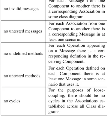
consistency rule description no invalid messages
For each Message from one Component to another there is a corresponding Association in some class diagram.
no untested messages
For each Association from one Component to another there is a corresponding Message in at least one scenario.
no undefined methods
For each Operation appearing on a Message there is a cor-responding defintion in the re-ceiving Component.
no untested methods
For each Operation defined on each Component there is at least one Message in some sce-nario that uses it.
no cycles
For the purposes of loose-coupling, there should be no cycles in the Associations es-tablished across all Class dia-grams.
Table 2. Some Consistency Rules.
fifty classes and comprised a few dozen independently de-veloped diagrams.
We will use a relational model to develop the formal as-pects of our architecture description as, we have discussed, many others have done before us [4, 11, 17, 18, 27].
The metamodel that the architecture team constructs at the outset might look like that shown in Figure 1 and have the consistency rules enumerated as in Table 2.
The metamodel says that the entities appearing on the diagrams will be Components, Associations, Messages and Operations. The Components and Associations will appear respectively as boxes and arrows on Class diagrams, such as in Figures 2 and 4. The Messages and Operations will appear on Sequence diagrams, such as in Figures 3 and 5. The diagrams record relational information about these en-tities. For example, the Class diagrams record the fact that each Association has a source and a target, both of which are Components. Similarly, the Sequence diagrams record the fact that each Message has a sender and a receiver (both Components) as well as a method, which is a operation of the receiver. The metamodel which captures these relation-ships, also assumes that we have an enumeration of the Op-erations of each Component.
Table 2 shows an initial set of consistency rules that we assume the architecture team have enumerated. These rules are simple, but typical of the structural consistencies that the team will be trying to achieve. Basically, the rules state
C1 C2
C3
Figure 2. Architect 1’s Class Diagram.
:C1 :C2 :C3
op2
op3
Figure 3. Architect 1’s Sequence Diagram.
that every Message should be from client to server, that every Message should be tested in some scenario and that (for loose-coupling) cycles in the Class diagrams are to be avoided. We will see that, while these rules can be obeyed, the architectural team eventually chooses to relax them (and consequently evolve the metamodel).
5. Consistency
Having agreed the metamodel and its rules, the team then begins independent development of separate parts of the ar-chitecture. Suppose Architect 1 comes up with the Class diagram in Figure 2 and the Sequence diagram in Figure 3. These two diagrams almost satisfy thefive rules of Table 2. In fact, our tool notes that there is an operation of C1 which is not tested (op1), but that is the only problem. Architect 1 is satisfied with this, because it is someone else’s task to exercise C1.
In practice, when an individual architect is working on a part of an architecture, they may be dealing with a few dozen Components and developing (say) a dozen or more scenarios. Arriving at an acceptable level of internal con-sistency will be an iterative process. Residual inconsisten-cies will be (the architect hopes) resolved when their part is combined with the other parts being developed concur-rently.
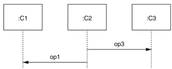
Architect 2 has, we imagine, concurrently developed the Class diagram shown in Figure 4 and the Sequence diagram shown in Figure 5. They receive much the same report as Architect 1 - all is consistent, except there is an operation of C2 that has not been tested (op2).
C1 C2
C3
Figure 4. Architect 2’s Class Diagram.
:C1 :C2 :C3
op1
op3
Figure 5. Architect 2’s Sequence Diagram.
However, when the two architects combine their models and run consistency checking again, they encounter a little difficulty.
While the inconsistencies that they knew about when de-veloping independently are resolved by the combination of models (now, all known Operations are tested), the com-bination of the Class diagrams has unfortunately created a loop in the Associations between C1 and C2. This is some-thing that will need to be resolved, either by one of the ar-chitects making modifictions to their contribution, or by a change to the metamodel.
The reason we are so concerned with inconsistency is that, for large systems, many components and many sce-narios will be defined and it will considerably improve the quality of the description if these individual descriptions are eventually made consistent, while for pragmatic reasons we must tolerate inconsistency during development.
In our example we have a choice of the remedial action to take. It may be possible for one architect to change their model. If not, the team will consider if the metamodel needs to be evolved.
In fact, here, we have probably made the loose-coupling constraint too strong. We might allow “local” loops within well defined subgraphs of the whole architecture. Here for example, it would be sufficient to allow loops between Components which are of length no greater than two. If A uses B, then allowing B to use A does not really damage the coupling, we could argue (a common feature in implemen-tations that use some form of callback).
In practice, we will wish to construct more complex rela-tions than those that we have exemplified here and for which
we will require more expressive forms than the simple rela-tional diagrams used in this section. In the next section we describe how we have based our tooling on the relational algebra, and how this both simplifies the encoding of the consistency rules and the evolution of the metamodel.
6. A Design Support Tool
The WAVE tool has been implemented to support the way of working outlined in Table 1 and illustrated in the previous section. The architects work concurrently on separate (over-lapping) parts of the architecture, recording their progress in a local copy of a “database”. In practice, we generate this database from whichever diagramming tool the architects choose to use, by dumping it as an XMIfile and importing it into the WAVE tool.
In the implementation we shall describe here (available from http://ecs.soton.ac.uk/˜ph/WAVE) the database is held as a set of relational tables and the consistency rules are implemented is scripts that compute new tables recording discovered inconsistencies.
The use of a relational model and of scripts to define the consistency rules makes the co-evolution of the metamodel particularly adaptable and straightforward.
For example, the script that computes the first consis-tency rule in Table 1 is written
invalid_messages =
diff(join(invert(sender),receiver), join(invert(source),target))
Here,joinis the relational join of two (binary) relations. The relations are those recorded in the metamodel (Figure 1) and the data in them records that displayed on the actual model diagrams. The operationinvert takes the inverse of a (binary) relation anddiffcomputes the set difference. So the above calculation constructs a relation which relates any two Components between which there is a Message (on some sequence diagram) but between which there is no cor-responding Association on any Class diagram. This com-puted relation is effectively an inconsistency report - listing those places where rule 1 is disobeyed.
The fact that WAVE is scripted and stores its data in re-lational tables (exportable as tables or as XML) means that generating reports of inconsistencies is also straightforward. Architects can thus work with independent copies of the database and work to extend their view of the architecture and to remove inconsistencies that are reported.
When databases are merged in WAVE the simplest, and apparently most effective, merge is simply to take the union of each copy of each relational table. WAVE has been specifically designed so that for most purposes this is the most effective merge. It does mean however that, if an entity appears in two copies of the database and is deleted by only
one of the architects, it will reappear on merge. If it was required that deletes by one architect would propagate on merge, then a more elaborate (diff3-like) merge is required. Since all operations on the database are scripted, including merge, making a domain-specific merge is as straightfor-ward as any metamodel evolution.
We have used WAVE on a number of small projects and a couple of fairly large ones. The largest has about fifty classes (actually, components) spread over about a dozen class diagrams and another dozen sequence diagrams. In the current version of the architecture described in this largest example, WAVE lists about twenty inconsistencies that are genuine inconsistencies between model-parts developed by different architects and a smaller number that are proba-bably going to require the metamodel (which includes the metamodel shown here as a subset) to be co-evolved. Run-ning the WAVE scripts against the XMIfiles for this archi-tecture (dumped, as it happens, from Sparx Systems’ En-terprise Architect) takes a few seconds. We have tested performance on an artificial example with around 1000 entries in each of the relational tables that are generated as intermediate structures in WAVE, to persuade ourselves that WAVE’s performance will scale to realistic large-scale models. These tests have shown that WAVE can process such tables with constraints such as those listed in Table 2 in seconds rather than minutes. A more comprehensive per-formance analysis will be completed soon.
7. Conclusions
We have described a method of developing architecture de-scriptions based on giving a sufficiently precise metamodel that consistency can be checked during architecture devel-opment.
Rather than insist that the architecture description is kept consistent at all times, we advocate a method of iterative and cooperative development that allows the description to be periodically inconsistent.
We have shown how the metamodel can be captured for-mally as a relational model and argued that this method is particularly appropriate to this style of development, not least of all because it encourages the architects to embrace the whole architecture at all times and to keep in mind how far from internal consistency the description may have drifted.
The tool we have described supports this method of working, where model and metamodel are co-evolved and where inconsistency is tolerated during development. For large scale systems, where iterative and cooperative work-ing is the norm, this tolerance of inconsistency is essential.
The method has been applied so far only to software in-tensive systems. It also seems appropriate to other domains. We have in hand experiments with metamodels for
docu-mentation [15], for reasoning [24, 13] and have an ambi-tion to extend the method to a broader range of systems, in particular those that have physical as well as logical struc-ture. Ultimately our plan is to combine these domains so that describing an architecture, documenting it and reason-ing about it will all be supported within the same frame-work.
References
[1] K. Balasubramanian, J. Balasubramanian, J. Parsons, A. Gokhale, and D. C. Schmidt. A platform independent component modeling language for distributed real-time and embedded systems. J. Comput. Syst. Sci., 73(2):171–185, 2007.
[2] B. Balzer. Tolerating inconsistency. InICSE ’91: Proceed-ings of the 13th international conference on Software
engi-neering, New York, NY, USA, 1991. ACM.
[3] D. Beyer. Relational programming with CrocoPat. InICSE. IEEE, 2006.
[4] D. Beyer, A. Noack, and C. Lewerenz. Efficient relational calculation for software analysis. Transactions on Software
Engineering, 31(2):137–149, 2005.
[5] K.-N. Chang. Consistency checks on UML diagrams. In International Conference on Software Engineering Research
and Practice, SERP07. IEEE, 2007.
[6] K.-N. Chang. Model checking consistency between se-quence and state diagrams. In International Conference
on Software Engineering Research and Practice, SERP08.
IEEE, 2008.
[7] C. Date.Database in Depth - Relational Theory for Practi-tioners. O’Reilly Media Inc., Sebastopol, CA, 2006. [8] U. Dekel and J. D. Herbsleb. Notation and representation in
collaborative object-oriented design: an observational study.
InSIGPLAN Notices, Volume 42 , Issue 10. ACM, 2007.
[9] A. Egyed. Instant consistency checking for the UML. In ICSE ’06: Proceedings of the 28th international conference
on Software engineering, pages 381–390, New York, NY,
USA, 2006. ACM.
[10] A. Egyed. Fixing inconsistencies in UML design models. In ICSE ’07: Proceedings of the 29th international conference
on Software engineering, New York, NY, USA, 2007. ACM.
[11] A. Egyed. UML/analyzer: A tool for the instant consistency checking of UML models. InICSE ’07: Proceedings of the
29th international conference on Software engineering, New
York, NY, USA, 2007. ACM.
[12] S. Fickas. Clinical requirements engineering. InIn ICSE 05: Proceedings of the 27th International Conference on
Soft-ware Engineering, pages 28–34. ACM Press, 2005.
[13] C. B. Haley, J. D. Moffett, R. Laney, and B. Nuseibeh. Ar-guing security: Validating security requirements using struc-tured argumentation. Inin Proceedings of the Third Sympo-sium on Requirements Engineering for Information Security (SREIS’05), co-located with the 13th International
Require-ments Engineering Conference (RE’05, 2005.
[14] P. Henderson. Laws for dynamic systems. InInternational
Conference on Software Re-Use (ICSR 98). IEEE, 1998.
[15] P. Henderson and N. de Silva. System architecture induces document architecture. In20th International Conference on Software Engineering and Knowledge Engineering (SEKE
2008). IEEE, 2008.
[16] P. Henderson and J. Yang. Reusable web services. In8th
International Conference on Software Reuse (ICSR 2004).
IEEE, 2004.
[17] R. C. Holt. Binary relational algebra applied to software architecture. InCSRI Technical Report 345. University of Toronto, 1996.
[18] D. Jackson. Software Abstraction. MIT Press, Cambridge, MA, 2006.
[19] P. Kruchten. Architectural Blueprints - the 4+1 view model of software architecture.IEEE Software, 12(6):42–50, 1995. [20] M. W. Maier and E. Rechtin.The Art of System Architecting,
2nd Ed.CRC Press LLC, Boca Raton, FL, 2002.
[21] S. Nejati, M. Sabetzadeh, M. Chechik, S. Easterbrook, and P. Zave. Matching and merging of statecharts specifications.
InIn 29th International Conference on Software
Engineer-ing (ICSE07), pages 54–64, 2007.
[22] B. Nuseibeh, S. Easterbrook, and A. Russo. Making incon-sistency respectable in software development. Journal of
Systems and Software, 58:171–180, 2001.
[23] N. Rozanski and E. Woods. Software Systems Architecture. Addison-Wesley, Upper Saddle River, NJ, 2005.
[24] J. Rushby.Modular Certification. SRI International, Menlo Park, CA, 2002.
[25] M. Sabetzadeh and S. Easterbrook. View merging in the presence of incompleteness and inconsistency.Requir. Eng., 11(3):174–193, 2006.
[26] M. Sabetzadeh, S. Nejati, S. Easterbrook, and M. Chechik. Global consistency checking of distributed models with tremer. InIn 30th International Conference on Software En-gineering (ICSE08), 2008. Formal Research Demonstration (To Appear.
[27] M. Sabetzadeh, S. Nejati, S. Liaskos, S. Easterbrook, and M. Chechik. Consistency checking of conceptual models via model merging. InIn RE, pages 221–230, 2007. [28] M. Shaw and P. Clements. The golden age of software
ar-chitecture. Software, March/April:31–39, 2006.
[29] M. Shaw and D. Garlan. Software Architecture -
Perspec-tives on an emerging discipline. Addison-Wesley, Upper
Saddle River, NJ, 1996.
[30] W. Shen, K. Compton, and J. Huggins. A toolset for support-ing UML static and dynamic model checksupport-ing. InIn Proc. 16th IEEE International Conference on Automated Software
Engineering (ASE, pages 147–152. IEEE Computer Society,