Abstract—The nodes in a wireless sensor network have limited energy and hence, lifetime maximization is the prime task during protocol design. Low Energy Adaptive Clustering Hierarchy (LEACH) protocol is a benchmark Clustering Protocol which imposes upon cluster heads the complete load of aggregation and relay of messages to base-station. Our protocol Assisted LEACH (A-LEACH) achieves lessened and uniform distribution of dissipated energy by separating the tasks of Routing and Data Aggregation. It introduces the concept of Helper Nodes which assist Cluster Heads for Multi-hop Routing. A new algorithm has been formulated to facilitate energy efficient Multi-hop Route Setup for helper nodes to reach base station. The proposed protocol extends the lifetime of the network, minimizes overall energy dissipation in the network and distributes dissipation among Cluster Heads, Sensor Nodes and Helper Nodes vis-´a-vis LEACH. This is substantiated by simulation results.
Index Terms—Clustering protocols, energy-efficient protocol, leach, multi-hop, routing protocols.
I. INTRODUCTION
There have been profound studies on Wireless Sensor Networks [1] during the recent years. As the sensors in the network have limited battery power, enhancing the lifetime of a network is the basic aim of designing an energy efficient routing protocol. Clustering protocols aim to achieve energy efficiency. The whole network is divided into clusters with a cluster head node for each cluster. The data from sensors inside a cluster is aggregated at cluster head. This eliminates a lot the redundancy in packet forwarding. Low Energy Adaptive Clustering Hierarchy (LEACH) [2] is considered to be benchmark protocol in Clustering/Hierarchical based protocols [3]. Multihop-LEACH [4], LEACH-MF [5], MR-LEACH [6], and Secure LEACH [7], or M-LEACH are examples of few Clustering Protocols derived from LEACH. In this paper, we propose Assisted-Leach Protocol abbreviated as A-LEACH. In most of the clustering protocols, the whole load of data aggregation and data routing is done by cluster heads. LEACH protocol [2] directly transmits aggregated data from cluster heads to the base station. This debilitate the lifetime of a network. We introduce the concept of Helper Nodes where a node closer to the base station in every cluster is assigned the routing job whereas cluster heads take care of data aggregation. We formulate a new idea for route formulation for the helper nodes to reach base station. Every helper node chooses as the next hop, the node nearest to the base station from all its neighboring helper
Manuscript received February 10, 2013; revise April 16, 2013. The authors are with the Computer Science and Engineering Department (e-mail: [email protected], [email protected]).
nodes. We use the Receive Signal Strength of Base Station Beckon signals to decide upon nodes nearer to base station in Helper nodes selection and route set up phases. Thus the dissipation energy is lessened due to multi-hop routing and the same is distributed among helper and cluster head nodes. We propose algorithms for helper node selection and multi-hop routing. Our algorithm for cluster head selection is an extension to LEACH's cluster head selection.
II. ALGORITHM FOR ASSISTED-LEACH
Assisted Leach protocol has the following sub-stages: Cluster Head Selection
Cluster Formation Helper Node Selection Routing Set-Up
Sensing, Aggregating and Routing A. Cluster Head Selection
The Cluster Head selection follows an extended procedure to Leach's [7] Cluster Head Selection. Each Node calculates its threshold based on the Formula:
𝑇 𝑛 =
𝑃
1 − 𝑃(𝑟 𝑚𝑜𝑑 𝑃1 ) 𝑖𝑓 𝑛 ∈ 𝐺
0.5 𝑃
1 − 𝑃(𝑟 𝑚𝑜𝑑 𝑃1 ) 𝑖𝑓 𝑛 ∈ 𝐻 0 𝑜𝑡𝑒𝑟𝑤𝑖𝑠𝑒
where
P: Desired Percentage of Cluster Heads r: Current Round in protocol operation
G: Set of Nodes that have neither been Cluster Heads nor
been Helper Nodes in the last 1𝑃 Rounds.
H: Set of Nodes that haven't been Cluster Heads but played
role of Helper Nodes in the last 1𝑃 Rounds
Each sensor elects itself to be a Cluster Head by picking up a random number between ’0’ and ’1’ and comparing it to be less than the threshold.
B. Cluster Formation
Cluster Heads broadcast a HEAD_BOAST message containing their IDs to facilitate cluster formation. It can happen that a non-cluster node receives such messages from different Cluster Heads. They decide upon the Cluster Head whose message possesses highest Received Signal Strength to be their head and send a JOIN_CLUSTER packet with their IDs to corresponding Cluster Heads showing consent to be part of their clusters.
Assisted-Leach (A-Leach) Energy Efficient Routing
Protocol for Wireless Sensor Networks
C. Helper Node Selection
Helper Node in a Cluster is the node which is nearer to the base station with sufficient remaining energy
Base Station sends a packet containing its ID to every node assuming that the base station can reach every node at single hop over a common channel
The nodes in each cluster store the Base Station ID from the received packet and then make a packet "RSS_PACKET" with the Received Signal Strength values (RSS Values) and (Self) Node ID as entries A copy of this "RSS_PACKET" is sent to the
corresponding Cluster Heads
Cluster Head elects the node which possessed packet with highest Received Signal Strength to be the Helper Node and sends an acknowledgement packet "Helper_BOAST" of the same to the respective node
In case of a tie with few nodes possessing same RSS values for the packets from base station, Cluster Head selects the one with highest remaining energy as the Helper Node This way, every Cluster possesses a Cluster Head and
Helper Node by now D. Routing Set-Up
This stage aims at finding the helper node at next hop for each helper node to route aggregated data to base station In this stage, only the helper nodes are operational and all
other nodes including cluster heads go into sleep mode Each Helper Node sends the "RSS_PACKET" made in
Helper Nodes Selection Phase to nodes in transmission range
Thereby, every helper node receives "RSS_PACKET" from all its neighbours
According to Helper Nodes Selection phase above, "RSS_PACKET" contains the Received Signal Strength (RSS) values of the packets received by corresponding neighbouring helper nodes from the base station as first entry and corresponding Node ID as second entry
Now, each helper node picks up the "RSS_PACKET" with maximum Received Signal Strength(RSS) value and stores the second entry Node ID as its next hop
Hence, every helper node chooses as its next hop the node nearest to base station out of its neighbouring helper nodes E. Sensing, Aggregation and Routing: Steady State Phase All above four stages form set-up phase and now, actual data transfer begins. Cluster Heads follow a TDMA schedule to assign timeslots for the sensor nodes inside the cluster. The sensor nodes send the sensed data to the corresponding Cluster Heads. The Cluster Heads aggregate the data, remove redundancies and forward the data to their Helper Nodes among which the actual Routing takes place. All other nodes except helper nodes go into sleep mode while routing takes place.
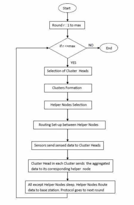
The Design of Protocol Operation is shown in Fig. 1. The data sensed at sensor nodes inside a cluster is sent to the Cluster Head. Cluster Heads Aggregate the data and send it to the Helper Node where all helper nodes are shown with links between them forming a virtual Routing Ground for routing aggregated data to the base station. Flow Chart of Operational Steps in shown in Fig. 2. Each round starts with the selection of cluster heads followed by formation of clusters by assigning cluster heads to all nodes in the network. This is followed by Helpers Nodes Selection and Route Set-Up between the Helpers Nodes by assigning next hop helper at each of the helper nodes to reach base station. This
is followed by actual sensing, data aggregation and routing the aggregated data to base station.
Fig. 1. Design for protocol operation.
Fig. 2. Flow chart for protocol operation.
III. ENERGY MODEL FOR COMMUNICATION
We assume a simple model accounting for the energy dissipation in routing packets inside the network similar to most of the clustering protocols [8].
𝑇𝑒 𝑑𝑖𝑠𝑠𝑖𝑝𝑎𝑡𝑖𝑜𝑛 𝑒𝑛𝑒𝑟𝑔𝑦 𝑓𝑜𝑟 𝑡𝑟𝑎𝑛𝑠𝑚𝑖𝑠𝑠𝑖𝑜𝑛 = k.Εelec + k.€amp.d2
d ≤ d0 = k.Εelec + k.€amp.d4 d > d0
𝑇𝑒 𝑑𝑖𝑠𝑠𝑖𝑝𝑎𝑡𝑖𝑜𝑛 𝑒𝑛𝑒𝑟𝑔𝑦 𝑓𝑜𝑟 𝑟𝑒𝑐𝑒𝑖𝑣𝑒𝑟 = k.Εelec
where
€amp: Energy dissipation of transmission amplifier
k: Message length in bits d: Distance between nodes d0: Threshold distance
The threshold distance d0 in the Simulations is assumed to be 70 percent of the maximum possible distance between the nodes in network during our simulations. Sensors transmit data to cluster head only when an event occurs. The base station node is assumed to be a high energy node or rechargeable node facilitating beckoning to all nodes during protocol operation.
IV. THEORETICAL ANALYSIS
LEACH [2] uses Single Hop transmission from Cluster Heads to Sink. Earlier Studies [9] show that Multi-hop relay from Nodes to Base Station is Energy Efficient than Single Hop Relay in most of the cases. We show here that Multi-hop Relay between Helper Nodes increases network lifetime compared to Multi-Hop between Cluster Heads [4] by reducing overall load of clustering and routing upon Cluster Heads.
Here, we compare the worst case energy dissipations for multi-hop transmission between Helper Nodes vs multi-hop transmission between Cluster Heads.
A. Multi-Hop via Cluster Heads
In worst case, the nearest possibility of a node to be cluster head again after once is 𝑃1 rounds later (𝑃 - cluster percentage). Consider two rounds '𝑟' and '𝑟 + 1𝑃 ' with two particular nodes (𝐶𝐻1, 𝐶𝐻2) from two different clusters which
are cluster heads in both rounds.
𝑇𝑒 𝐸𝑛𝑒𝑟𝑔𝑦 𝐷𝑖𝑠𝑠𝑖𝑝𝑎𝑡𝑒𝑑 𝑓𝑜𝑟 𝐶𝐻1
= 𝐴𝑔𝑔𝑟𝑒𝑔𝑎𝑡𝑖𝑜𝑛ˍ𝐸𝑛𝑒𝑟𝑔𝑦𝑟 + 𝑅𝑜𝑢𝑡𝑖𝑛𝑔ˍ𝐸𝑛𝑒𝑟𝑔𝑦𝑟+
𝐴𝑔𝑔𝑟𝑒𝑔𝑎𝑡𝑖𝑜𝑛ˍ𝐸𝑛𝑒𝑟𝑔𝑦𝑟+ 1 𝑃 + 𝑅𝑜𝑢𝑡𝑖𝑛𝑔ˍ𝐸𝑛𝑒𝑟𝑔𝑦𝑟+ 1
𝑃
= 2𝐴 + 2𝑅
(𝐴𝑠𝑠𝑢𝑚𝑒 𝑏𝑜𝑡 𝑛𝑜𝑑𝑒𝑠 𝑎𝑣𝑒 𝑠𝑜𝑤𝑛 𝑢𝑝 𝑠𝑎𝑚𝑒
𝐴𝑔𝑔𝑟𝑒𝑔𝑎𝑡𝑖𝑜𝑛 𝑒𝑛𝑒𝑟𝑔𝑦 ′𝐴′ 𝑎𝑛𝑑 𝑅𝑜𝑢𝑡𝑖𝑛𝑔 𝐸𝑛𝑒𝑟𝑔𝑦 ′𝑅′)
𝑇𝑒 𝐸𝑛𝑒𝑟𝑔𝑦 𝐷𝑖𝑠𝑠𝑖𝑝𝑎𝑡𝑒𝑑 𝑓𝑜𝑟 𝐶𝐻2
= 𝐴𝑔𝑔𝑟𝑒𝑔𝑎𝑡𝑖𝑜𝑛ˍ𝐸𝑛𝑒𝑟𝑔𝑦𝑟+ 𝑅𝑜𝑢𝑡𝑖𝑛𝑔ˍ𝐸𝑛𝑒𝑟𝑔𝑦𝑟+
𝐴𝑔𝑔𝑟𝑒𝑔𝑎𝑡𝑖𝑜𝑛ˍ𝐸𝑛𝑒𝑟𝑔𝑦𝑟+ 1 𝑃
+ 𝑅𝑜𝑢𝑡𝑖𝑛𝑔ˍ𝐸𝑛𝑒𝑟𝑔𝑦𝑟+ 1
𝑃
= 2𝐴 + 2𝑅
(𝐴𝑠𝑠𝑢𝑚𝑒 𝑏𝑜𝑡 𝑛𝑜𝑑𝑒𝑠 𝑎𝑣𝑒 𝑠𝑜𝑤𝑛 𝑢𝑝 𝑠𝑎𝑚𝑒
𝐴𝑔𝑔𝑟𝑒𝑔𝑎𝑡𝑖𝑜𝑛 𝑒𝑛𝑒𝑟𝑔𝑦 ′𝐴′ 𝑎𝑛𝑑 𝑅𝑜𝑢𝑡𝑖𝑛𝑔 𝐸𝑛𝑒𝑟𝑔𝑦 ′𝑅′)
B. Multi-Hop via Helper Nodes
This is the scenario shown up in our protocol A-LEACH. Consider two rounds '𝑟' and '𝑟 + 1𝑃 ' with two particular nodes which can be (𝐶𝑙𝑢𝑠𝑡𝑒𝑟𝐻𝑒𝑎𝑑, 𝐻𝑒𝑙𝑝𝑒𝑟) or
(𝐻𝑒𝑙𝑝𝑒𝑟1, 𝐻𝑒𝑙𝑝𝑒𝑟2) or (𝐶𝑙𝑢𝑠𝑡𝑒𝑟𝐻𝑒𝑎𝑑1, 𝐶𝑙𝑢𝑠𝑡𝑒𝑟𝐻𝑒𝑎𝑑2)
Applying the fact that Cluster Heads Aggregate Data (Aggregation Dissipation Energy - A) and Helper Nodes Route (Routing Dissipation Energy - R), Energy Dissipations are notated as follows for the possible cases:
𝐸(𝐶𝑙𝑢𝑠𝑡𝑒𝑟𝐻𝑒𝑎𝑑, 𝐻𝑒𝑙𝑝𝑒𝑟)
= 2𝐴 (𝐹𝑜𝑟 𝐶𝑙𝑢𝑠𝑡𝑒𝑟 𝐻𝑒𝑎𝑑 𝑖𝑛 𝐵𝑜𝑡 𝑅𝑜𝑢𝑛𝑑𝑠)
= 2𝑅 (𝐹𝑜𝑟 𝐻𝑒𝑙𝑝𝑒𝑟 𝑁𝑜𝑑𝑒 𝑖𝑛 𝐵𝑜𝑡 𝑅𝑜𝑢𝑛𝑑𝑠)
𝐸(𝐻𝑒𝑙𝑝𝑒𝑟1, 𝐻𝑒𝑙𝑝𝑒𝑟2)
= 2𝐴 (𝐹𝑜𝑟 𝐻𝑒𝑙𝑝𝑒𝑟1 𝑖𝑛 𝐵𝑜𝑡 𝑅𝑜𝑢𝑛𝑑𝑠) = 2𝑅 (𝐹𝑜𝑟 𝐻𝑒𝑙𝑝𝑒𝑟2 𝑖𝑛 𝐵𝑜𝑡 𝑅𝑜𝑢𝑛𝑑𝑠) 𝐸(𝐶𝑙𝑢𝑠𝑡𝑒𝑟𝐻𝑒𝑎𝑑1, 𝐶𝑙𝑢𝑠𝑡𝑒𝑟𝐻𝑒𝑎𝑑2)
= 2𝐴 (𝐹𝑜𝑟 𝐶𝑙𝑢𝑠𝑡𝑒𝑟𝐻𝑒𝑎𝑑1 𝑖𝑛 𝑏𝑜𝑡 𝑅𝑜𝑢𝑛𝑑𝑠) = 2𝑅 (𝐹𝑜𝑟 𝐶𝑙𝑢𝑠𝑡𝑒𝑟𝐻𝑒𝑎𝑑2 𝑖𝑛 𝑏𝑜𝑡 𝑅𝑜𝑢𝑛𝑑𝑠)
All the above three cases show that total energy dissipation in both rounds for each of the two considered nodes (2R or 2A) is less in section IV- 2 than that of individual nodes dissipation energy (2A + 2R) in Section IV-1.
Hence, we can say that the multi-hop routing with concept of sharing Routing and Data Aggregation between Helper Nodes and Cluster Heads increases Network Life Time.
V. PSEUDO CODES
A. Cluster Head Selection
Nodes ⇽ Set of all Nodes
∀n in Nodes:
if(RoundˍHistoryˍCH n ≥
P1 && 𝑅𝑜𝑢𝑛𝑑ˍ𝐻𝑖𝑠𝑡𝑜𝑟𝑦ˍ𝐻𝑁 n ≥ 1P )
Th ⇽ P 1−P∗(r mod 1
P )
/∗ n is neither cluster head nor helper in last 1P rounds ∗/
elseif(RoundˍHistoryˍCH n ≥ 1P )
Th ⇽ 0.5 ∗ P
1−P∗(r mod 1P )
/∗ n isn′t cluster head in last 1
P rounds but can be Helper ∗/
else Th ⇽ 0 endif
if(random number in 0,1 < 𝑇)
state n ⇽ HEAD endif
B. Cluster Formation
Nodes ⇽ Set of all Nodes
∀n in Nodes:
if(state n = HEAD)
broadcast HEADˍBOAST messages with node′s ID
wait for JOINˍCLUSTER messages
/∗ JOINˍCLUSTER is request of a node to it′s Cluster Head
to join it′s Cluster ∗/
/∗ HEADˍBOAST is declaration that node is a head ∗/
if(receive JOINˍCLUSTER from node with id = "ID")
ADD "ID" to clusterˍmembers[n]
endif endif
if(state n = NORMAL)
receive all HEADˍBOAST messages
Select the "Cluster Head" with maximum RSS
Send JOINˍCLUSTER messages to "Cluster Head"
myhead n ⇽ "Cluster Head"
𝑒𝑛𝑑𝑖𝑓
C. Helper Node Selection
Nodes ⇽ Set of all Nodes
∀n in Nodes:
if(state n = NORMAL) receive BaseˍStationˍBeckon
/∗ Beckon Signal sent from basestation to all nodes ∗/ send a copy of RSSˍPACKET(RSS BaseˍStationˍBeckon , NODE ID) to myhead[n]
/∗ All nodes send received signal strength of beckon from
basestation to their cluster heads ∗/
wait for HELPERˍBOAST from myhead[n] if(receive HELPERˍBOAST from myhead[n]) state n ⇽ HELPER
/∗ HELPERˍBOAST is declaration of node to be helper ∗/ endif
endif
𝑖𝑓(𝑠𝑡𝑎𝑡𝑒 𝑛 = 𝐻𝐸𝐴𝐷)
𝑟𝑒𝑐𝑒𝑖𝑣𝑒 𝑅𝑆𝑆ˍ𝑃𝐴𝐶𝐾𝐸𝑇 𝑓𝑟𝑜𝑚 𝑐𝑙𝑢𝑠𝑡𝑒𝑟ˍ𝑚𝑒𝑚𝑏𝑒𝑟𝑠 𝑛
/∗ 𝑅𝑆𝑆ˍ𝑃𝐴𝐶𝐾𝐸𝑇 𝑐𝑜𝑛𝑡𝑎𝑖𝑛𝑠 𝑅𝑆𝑆 𝐵𝑎𝑠𝑒ˍ𝑆𝑡𝑎𝑡𝑖𝑜𝑛ˍ𝐵𝑒𝑐𝑘𝑜𝑛 𝑖. 𝑒. 𝑟𝑒𝑐𝑒𝑖𝑣𝑒𝑑 𝑠𝑖𝑔𝑛𝑎𝑙 𝑠𝑡𝑟𝑒𝑛𝑔𝑡 𝑜𝑓 𝑏𝑒𝑐𝑘𝑜𝑛 𝑠𝑖𝑔𝑛𝑎𝑙 𝑓𝑟𝑜𝑚 𝑏𝑎𝑠𝑒
𝑏𝑎𝑠𝑒𝑠𝑡𝑎𝑡𝑖𝑜𝑛 𝑎𝑛𝑑 𝑁𝑂𝐷𝐸 𝐼𝐷 ∗/
𝑠𝑒𝑙𝑒𝑐𝑡 "member" with highest 𝑅𝑆𝑆 𝐵𝑎𝑠𝑒ˍ𝑆𝑡𝑎𝑡𝑖𝑜𝑛ˍ𝐵𝑒𝑐𝑘𝑜𝑛 𝑠𝑒𝑛𝑑 𝐻𝐸𝐿𝑃𝐸𝑅ˍ𝐵𝑂𝐴𝑆𝑇 𝑡𝑜 "𝑚𝑒𝑚𝑏𝑒𝑟"
𝑒𝑛𝑑𝑖𝑓
/∗ 𝐻𝐸𝐿𝑃𝐸𝑅ˍ𝐵𝑂𝐴𝑆𝑇 𝑖𝑠 𝑑𝑒𝑐𝑙𝑎𝑟𝑎𝑡𝑖𝑜𝑛 𝑜𝑓 𝑛𝑜𝑑𝑒 𝑡𝑜 𝑏𝑒 𝑒𝑙𝑝𝑒𝑟 ∗/
D. Routing Set-Up Phase to Find Next Hop in Routing
HelperˍNodesˍList ⇽ Set of all Helper Nodes
∀n in HelperˍNodesˍList:
send RSSˍPACKET over it′s transmission range /∗ To Neighbouring Helper Nodes ∗/
/∗ RSSˍPACKET is the packet made in Helper Node selection
phase section V. 3 which contains received signal strength of beckon signal sent by basestation and node id ∗/
∀n in HelperˍNodesˍList:
wait for RSSˍPACKET from neighbours
/∗ Neighbours are neighbouring helper nodes whose
transmission range includes node n ∗/
if(receive RSSˍPACKET from Neighbours) Add RSSˍPACKET to NextˍHopsˍList endif
Select Node with highest RSS value inside RSSˍPACKET
from NextˍHopsˍList as "Next Hop"
VI. PERFORMANCE RESULTS TABLEI:SIMULATION PARAMETERS
K 600
Εelec 50nJ/bit
€amp 100pJ/bit/sq.unit
Bit Compression Cost 5pJ/bit
Energy of Node 2J
Nodes Number 100
Rounds 2000
Area 100X100 sq.units
Cluster Percentage 0.1
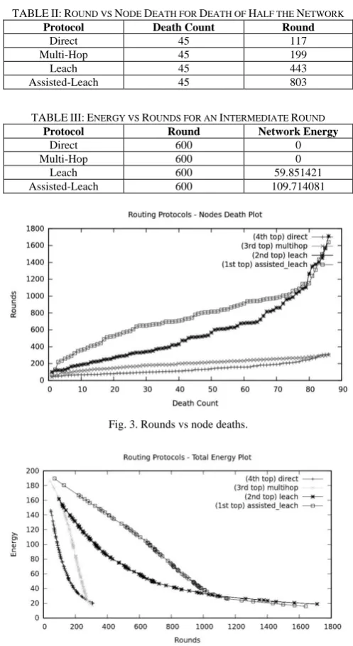
We have simulated direct transmission, multi-hop transmission, Leach and our proposed protocol Assisted Leach in C language. We have substantiated our theoretical analysis with simulation results using the parameters shown in Table I. We have collected the round numbers for deaths of
all nodes during simulation of the four protocols. For optimal comparison, data for death of half the network is shown in Table II and Fig. 3 is the plot for the whole data. We have collected the values of total energy in the network after every death in nodes for all the four protocols. Table III has the data for an intermediate round depicting the network energies and Fig. 4 is the plot for all the data. Half of the network in other protocols dies at almost half the rounds taken for death of half the network in Assisted-Leach.
TABLEII:ROUND VS NODE DEATH FOR DEATH OF HALF THE NETWORK
Protocol Death Count Round
Direct 45 117
Multi-Hop 45 199
Leach 45 443
Assisted-Leach 45 803
TABLEIII:ENERGY VS ROUNDS FOR AN INTERMEDIATE ROUND
Protocol Round Network Energy
Direct 600 0
Multi-Hop 600 0
Leach 600 59.851421
Assisted-Leach 600 109.714081
Fig. 3. Rounds vs node deaths.
Fig. 4. Network energy vs rounds.
VII. CONCLUSION
Helper Nodes in Assisted LEACH (A-LEACH) protocol has improved the lifetime of the network by distributing the minimized energy dissipation throughout the nodes. Theoretical analysis and simulation results substantiate this.
ACKNOWLEDGEMENT
Thanks to Professor Ajit Pal and few other Professors at CSE, IIT Kharagpur for assistance in idea formulation and validating the simulation results.
REFERENCES
[1] F. Akyildiz and W. Su, “A survey on sensor networks,”
Communications Magazine, IEEE, vol. 40, no. 8, pp. 102-114, 2002.
[2] W. Heinzelman, A. Chandrakasan, and H. Balakrishnan, “Energy-Efficient communication protocol for wireless sensor networks,” in Proc. the Hawaii International Conference on System
Sciences, Hawaii, January 2000.
[3] A. Joshi and P. M. Lakshmi, “A survey of hierarchical routing protocols in wireless sensor networks,” International Journal of
Wireless and Mobile Networks, vol. 4, no. 4, Aug. 2012.
[4] R. V. Biradar, S. R. Sawant, R. R. Mudholkar, and V. C. Patil, “Multihop routing in self-organizing wireless sensor networks,” in
Proc. IJCSI International Journal of Computer Science Issues, vol. 8,
issue 1, January 2011, pp. 155-164.
[5] J. F. Yan and Y. L. Liu, “Improved leach routing protocol for large scale wireless sensor networks routing,” in Proc. 2011 International
Conference on Electronics, Communications and Control (ICECC), pp.
3754-3757.
[6] M. O. Farooq, A. B. Dogar, and G. A. Shah, “MR-LEACH: Multi-hop routing with low energy adaptive clustering hierarchy,” in Proc. 2010 Fourth International Conference on Sensor Technologies and Applications, pp. 262-268.
[7] J. Wang, G. Yang, and S. Chen, “Secure LEACH routing protocol based on low-power cluster-head selection algorithm for wireless sensor networks,” in Proc. 2007 International Symposium on
Intelligent Signal Processing and Communication Systems,
Nov.28-Dec.1, 2007 Xiamen, China, pp. 341-344.
[8] E. Abdellah, S. Benalla, A. B. Hssane, and M. L. Hasnaoui, “Advanced low energy adaptive clustering hierarchy,” International Journal on Computer Science and Engineering, vol. 02, no. 07, pp. 2491-2497, 2010.
[9] S. Fedor and M. Collier, “On the problem of energy efficiency of multi-hop vs one-hop routing in wireless sensor networks,” in Proc. 21th International Conference on Advanced Information Networking and Applications Workshops (AINAW’07).
Sunkara Vinodh Kumar was born in Visakhapatnam, Andhra Pradesh on April 10, 1991. He is currently pursuing Fourth Year B. Tech (Honors) from computer science and engineering department, IIT Kharagpur, India. He was SUMMER INTERN at Telecommunication Networks Group, TU Berlin, Germany in the year 2012. He was an Indian Academy of Sciences, Bangalore SUMMER FELLOW in the year 2011. He is placed as Software Engineer at Yahoo, India during campus placements in IIT Kharagpur for the year 2013. He is first author of Technical Report published at TKN Technical Report Series, TKN-12-003, Telecommunication Networks Group, TU Berlin, 2012. He is first author of” Demo Abstract: TWIST Actu-A RESTful Testbed Platform for Remote Experimentation With Building Automation Sensors and Actuators” published at ACM BuildSys 2012 workshop, part of Sensys’12, Toronto, Canada. His Research Interests include Computer Networks, Wireless Sensor Networks. Mr. Kumar has been a Winner at Hack U, 2013 conducted by YAHOO company in IIT Kharagpur, India.