Stereo Vision Based Depth Estimation Algorithm
In Uncalibrated Rectification
Abstract— In stereo vision application, the disparity between the stereo images allows depth estimation within a scene. Detecting conjugate pair in stereo images is a challenging problem known as the correspondence problem. In this paper, an overview of stereo vision is introduced as well as an efficient algorithm and a simple method in depth estimation. We use in this paper the well known matching algorithm, S URF, and we remove the outliers by applying geometric and epipolar constraints. Unlike most of the researchers, we calculate the depth without disparity map. We used the difference s between the inliers points resulting from epipolar constraint to get the maximum and the minimum disparity. The depth can be calculated easily from the minimum and the maximum disparity by taking the mean value. To confirm the results we apply on all methods used in estimating the fundamental matrix. Experimental results show that our algorithm in depth estimation works quite robustly.
Index Term— Stereo vision, depth estimation, SURF, disparity, correspondence problem,fundamental matrix
I. INTRODUCTION
Stereo vision systems are used to determine depth from two images taken at the same time but from slightly different viewpoints using two cameras.
Any two images of a common scene are related by an epipolar geometry, and corresponding points in the two images are constrained to lie on pairs of conjugate epipolar lines [1]. An assignment of the stereo matching algorithm is to find such points in the both images that represent the same scene point A stereo vision application such as a stereo vision mobile robot navigation requires a number of various capabilities, including the ability to execute uncomplicated goal-achieving actions, like reaching a given location; to react in real time to unexpected events, like the sudden appearance of an obstacle; to build, use and maintain a map of the environment; to determine the robot's position with respect to this map; to form plans that pursue specific goals or avoid undesired situations; and to adapt to changes in the environment [2]. In order to achieve the pre-mentioned goals, depth estimation of the navigated mobile robot is an essential demand. In literature, there are two approaches: the first one that try to get depth estimation based on disparity map computation using modern stereo vision system for images that are captured by the cameras placed in such positions so that a scene is taken from two slightly different views . Such systems required knowing the intrinsic and the extrinsic parameters of the used camera via camera calibration in order to make the rectification process in preprocessing stage before stereo matching [3-8 ]. The second approach proceeds
to rectify images directly from a set of matched points [9,10 ]. We follow a similar approach and present a simple
algorithm to get depth estimation directly from the inlier points resulting from the fundamental matrix. The fundamental matrix is estimated using point correspondences between two images. The difficulties in estimating the fundamental matrix lies in fact that there are often a fair portion of mismatches in a given set of point correspondences. It is therefore important that the method used for estimating the matching points and the method used to estimate the fundamental matrix should be robust. The known algorithms for stereo matching can be classified in two basic categories: Feature-based algorithms and area based algorithms [2]. The algorithms of both categories often use special methods to improve the matching reliability. Matas et al [11] find maximally stable extremely regions (MSER) correspondences between image elements from two images with different viewpoints. This method of extracting a comprehensive number of corresponding image elements contributes to the wide-baseline matching, and it has led to better stereo matching and object recognition algorithms. David. G and Lowe [12] proposed a scale invariant feature transform (SIFT) detector and descriptor, which detects a set of local feature vectors through scale space extremes and describe this feature using 3D histogram of gradien t and orientation. Also Hess [13] introduced an open source SIFT library. Herbert Bay, et. al, [14] proposed SURF (Speeded-Up Robust Features) as a fast and robust algorithm for local, similarity invariant image representation and comparison. SURF selects interest points of an image from the salient features of its linear scale-space, and then builds local features based on the image gradient distribution. An open source SURF library is introduced by Evans, C. [15]. There are several algorithms for robust estimation of the fundamental matrix [1]: The norm8point algorithm is the simplest method of computing the fundamental matrix, involving no more than the construction and least squares solution of a set of linear equations. M-Estimators [16] reduce effect of inliers with large noise or outliers by applying weight functions. RANSAC (RANdom Sample Consensus) technique [17] is a simple and successful method, it removes the effect of outliers by using random sampling as a search engine for inliers in the data set, the one that maximizes the cost function is chosen. A group of robust methods are developed based on RANSAC. LMeds (Least Median of squares) and LTS (Least Trimmed Squares) are similar to RANSAC, except for the way to determine the best solution.
Ashraf Anwar Fahmy
In this paper, we use SURF matching algorithm for collecting interest points from each image because it gives better matching results. The fundamental matrix is obtained by the five pre-mentioned methods and we compare between them from point of view of accuracy of depth estimation. The depth estimated is then calculated by getting the median between maximum and minimum disparity resulting from the inlier points in the left image and in the right image. We use the surveyor robot SVS [18], in Fig. 1, in this research paper to get the stereo images from different distances from an object. This paper is organized as follows: section II presents the stereo vision. Methodology is illustrated in section III. proposed algorithm is shown in section IV. Experimental results are presented in section V. Finally section VI concludes this paper.
Fig. 1. SVS surveyor robot
II. STEREO VISION
A. Basics
The geometric basis key problem in stereo vision is to find corresponding points in stereo images. Corresponding points are the projections of a single 3D point in the different image
Fig. 2. Stereo vision basics
spaces. The difference in the position of the corresponding points in their respective images is called disparity, Fig. 2. Two cameras: Left and Right, Optical centers: Ol and Or. Virtual image plane is projection of actual image plane through optical centre. Baseline, B is the separation between the optical centers . Scene Point, P, imaged at Pl and Pr. Disparity, is the amount by which the two images of P are displaced relative to each other.
d = xr – xl. (1)
Disparity Depth, Z=Bf/d (2)
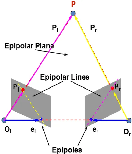
In addition to providing the function that maps pair of corresponding images points onto scene points, a camera model can be used to constraint the search for corresponding image point to one dimension. Any point in the 3D world space together with the centers of projection of two cameras systems, defines an epipolar plane. The intersection of such a plane with an image plane is called an epipolar line, Fig. 3. Every point of a given epipolar line must correspond to a single point on the corresponding epipolar line. The search for a match of a point in the first image therefore be reduced to a one-dimensional neighborhood in the second image plane.
Fig. 3. Epipolar lines and epipolar planes B. Correspondence problem:
There are two issues, how to select candidate matches? and how to determine the goodness of a match? Two main classes of correspondence (matching) algorithm: First, Correlation-based, attempt to establish a correspondence by matching image intensities, usually over a window of pixels in each image. Second Feature-based, attempt to establish a correspondence by matching sparse sets of image features, usually edges. Disparity map is sparse, and number of points is related to the number of image features identified . Feature-based methods, suitable when good features can be extracted from the scene, faster than correlation -based methods, provide sparse disparity maps, suitable for applications like visual navigation, and relatively insensitive to illumination changes.
III. METHODOLOGY
A. Data source.
500MHz Analog Devices Blackfin BF537 Processor (1000 integer MIPS), 32MB SDRAM, 4MB SPI Flash, JTAG, external 32-pin i/o header w/ 2 UARTS, 4 timers (PWM/PPM), SPI, I2C, 16 GPIO
Omnivision OV9655 1.3 megapixel sensor with AA format header and interchangeable lens - M12 P0.5 format - 3.6mm f2.0 (90-deg FOV) or optional 2.2mm f2.5 (120-deg FOV)
B. Feature detection.
Speeded Up Robust Features (SURF) is a robust local feature detector, first presented by Herbert Bay et. [14], that can be used in computer vision tasks like object recognition or 3D reconstruction. SURF is based on sums of 2D Haar wavelet responses and makes an efficient use of integral images. The steps of features detection as follows:
Interest points are selected at distinctive locations in the image, such as corners, blobs, and T-junctions. The most valuable property of an interest point detector is its repeatability, i.e. whether it reliably finds the same interest points under different viewing conditions. Next, the neighborhood of every interest point is
represented by a feature vector. This descriptor has to be distinctive and, at the same time, robust to noise, detection errors, and geometric and photometric deformations.
Finally, the descriptor vectors are matched between different images. The matching is often based on a distance between the vectors, e.g. the Mahalanobis or Euclidean distance. The dimension of the descriptor has a direct impact on the time this takes, and a lower number of dimensions is therefore desirable.
C. Stereo matching.
The detection feature points must be matched. There exist several matching techniques based on various algorithms, e.g. Correlation (C), Normalized Cross Correlation (NCC), Sum of Squared Differences (SSD) and Sum of Absolute Differences (SAD) algorithms.
The SAD algorithm is one of the simplest of dissimilarity measures of the left and right stereo images corresponding with square windows. Hence, the algorithm was chosen for the proposed algorithm. It computes the intensity differences for each center pixel (i, j) in a window W(x, y) as follows:
( ) ∑( ) ( )| ( ) ( )| (3)
Where IL and IR are pixel intensity functions of the left and right image respectively, W( x, y) is square window that surrounds the position (x, y) of the pixel. The disparity SAD (x, y, d) calculation is repeated within the x-coordinate frame in the image row, defined by zero and maximum possible disparity dmax of the searched 3D scene. The minimum difference value over the frame indicates the best matching pixel, and position of the minimum defines the disparity of the actual pixel [7].
D. The Fundamental matrix.
The fundamental matrix F is a 3×3 matrix which relates corresponding points in stereo images. In epipolar geometry, with homogeneous image coordinates , x and x′, of corresponding points in a stereo image pair, Fx describes a line (an epipolar line) on which the corresponding point x′ on the other image must lie. That means, for all pairs of corresponding points holds
(4)
The correctly matched points must satisfy epipolar constraints. This means that a point must lie on the epipolar line determined by its corresponding point. There are different algorithms for estimating the fundamental matrix given a set of point correspondence between two images:
Norm8-point algorithm: It is the simplest method of computing the fundamental matrix, involving no more than the construction and applying least –squares solution of linear equations. The key process with the 8-point algorithm is proper careful normalization of the input data before constructing the equations to solve [1]. MSAC: estimator Sample Consensus. The aim of M-estimators is to follow maximum-likehood formulations by deriving optimal weight for the data under non -Gaussian conditions. The estimators minimize the sum of a symmetric, positive definite functions of the errors [18 ]
RANSAC: RANdom SAmple Consensus. It can be considered like a search engine. It selects repeatedly a random sample of 7 correspondences and computes the inliers realizing the fundamental matrix. The solution with the most inliers retained [1].
LMeds: Least Median of Squares . It is similar to RANSAC except for the way to determine the best solution [18].
LTS: Least Trimmed Squares . It is a robust statistical method that fits a function to a set of data whilst not being unduly affected by the presence of outliers. It is one of a number of methods for robust regression. Instead of the standard least squares method, which minimizes the sum of squared residuals over n points, the LTS method attempts to minimize the sum of squared residuals over a subset, k, of those points. The n -k points which are not used do not influence the fit.
E. Depth Estimation
We can get disparity ( max, min) from the inlier points in both the left image and in the right image, obtained as output from fundamental matrix
[∑ | ( ) ( )|] (5)
[∑ | ( ) ( )|] (6)
Where, InL, InR are the inlier points in the left and in the right image respectively
(7)
(8)
Where, B base line between the left and right camera, focal length
(9)
The min. depth accuracy is calculated according to the following formula:
|
| (10)
The depth accuracy of the mean is calculated according to the following formula:
|
| (11)
IV. PROPOSED ALGORITHM
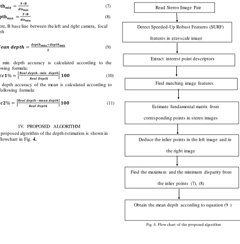
The proposed algorithm of the depth estimation is shown in the flowchart in Fig. 4.
Fig. 4. Flow chart of the proposed algorithm Read Stereo Image Pair
Detect Speeded-Up Robust Features (SURF)
features in grayscale image
Extract interest point descriptors
Find matching image features
Estimate fundamental matrix from
corresponding points in stereo images
Deduce the inlier points in the left image and in
the right image
Find the maximu m and the minimum disparity from
the inlier points (7), (8)
Fig. 5. T ested Image pair
A. Processing Steps.
In order to assess the performance of the algorithm, we test
on a set of images captured by stereo vision system of SVS surveyor robot. The image-pairs are captured at different distances, 50cm, 100cm, 150cm, 200cm, 250cm, and 300cm, as shown in Fig. 5.
B. Scope and Limitations.
This research has focused on the study of developing stereo vision depth estimation algorithm for mobile robot applications. Mobile robots are able to navigate both indoor and outdoor environments. Due to the large amount of material and also rough terrain in outdoor environments, our stereo vision depth perception algorithm have been executed for indoor applications
V. EXPERIM ENTAL RESULT
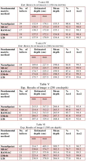
The simulation is performed us ing matlab software (R2012a). The computer processor is Intel ® core TM, i5, M430, 2.27 GHz. The proposed algorithm is simulated and processed on every image pair a, b, c, d, e, f, for all the specified methods used in fundamental matrix estimation in section III. We perform 50 run simulations for every image pair and then take the mean value. The experimental results for every image pair a, b, c, d, e, f are tabulated in Table 1 to Table 6 respectively.
TABLE I
EXP. RESULTS OF IMAGE A (50CM-DEP TH)
Fundament al matrix method
No. of inli ers
Estimated depth (cm)
Mean de pth
% Acc1
% Acc2
min max
Norm8point 77 49.4 63.1 56.3 99.0 87.4
MS AC 28 50.1 65.4 57.7 99.8 84.6
RANS AC 29 50.3 58.3 54.3 99.4 91.4
LMeds 41 50.2 58.1 54.2 99.6 91.6
LTS 34 49.4 61.9 55.9 99.8 88.2
TABLE II
EXP. RESULTS OF IMAGE B (100CM-DEP TH)
Fundament al matrix method
No. of inlie rs
Estimated depth (cm)
Mean depth
% Acc1
% Acc2
min max
Norm8point 83 92.3 118.3 105.3 92.3 94.7
MS AC 29 93.1 113.6 103.4 93.1 96.6
RANS AC 28 93.0 113.8 103.5 93.0 96.5
LMeds 39 92.9 113.9 103.4 92.9 96.6
LTS 40 93.0 115.0 104.0 93.0 96.0
a
b
c
d
e
We can deduce the following from the previous results: At near depth (50 cm), the depth accuracy gives better
results when the minimum estimated depth (%Acc1) is provided.
The Norm8point gives the maximu m number of the inliers and it is the fastest one, although it gives slightly lower accuracy results than the other methods.
The accuracy of the mean depth range (%Acc2) in all tested ranges is reasonable, robust, and consistent.
The metric threshold in SURF algorithm is setting to 1000 at all ranges except at 250cm and 300cm, it is setting to 500 to increase the detected matching points and then the inliers are increased (min. is 7).
VI. CONCLUSION
We have presented an efficient and robust algorithm in depth estimation suitable for mobile robot navigation and obstacle detection in real time applications. The depth is calculated directly from the inliers resulting from the fundamental matrix, by getting the mean value between the maximum disparity and the minimum disparity. To confirm the results, we compare the accuracy of depth estimation, between different methods used in obtaining the fundamental matrix and we get reasonable, robust, and consistent results. We reached 97.5% accuracy in depth estimation in average. Future research in this area is to implement SURF algorithm in real time stereo vision based navigation and obstacle avoidance for autonomous mobile robot
REFERENCES
[1] Hartely, R.I., Zisserman, A., "Multiple View Geometry in Computer Vision. 2edn. Cambridge Press 2004
[2] Nalpantidis, Lazaros; Gasteratos, A.; Sirakoulis, G.C.,(2008)"Review of stereo vision algorithms : From software to hardware'', International Journal of Optomechatronics, Vol. 2, No. 4, 435-462, 2008
[3] Harkanwal, et al. (2011)," A robust area based disparity estimation technique for stereo vision applications", proceeding of the 2011 International conference on image processing.
[4] Meng Chen, et al.,"A method for mobile robot obstacle avoidance based on stereo vision", proceeding 10th IEEE International conference on components, circuits, devices, and systems, 2012 [5] Zhao Yong-guo, et al. "T he obstacle avoidance and navigation based on stereo vision for mobile robot" proceeding international conference on optoelectronics and image processing., 2010 [6] Ming Bai, et al., "Stereovision based obstacle detection appro ach
for mobile robot navigation", proceeding international conference on intelligent control and information processing, 2010. [7] Patrik Kamencay, et al., "Improved depth map estimation from
stereo images based on hybrid method", Radio engineering, vol. 21, NO. 1, pp. 70-78, 2012.
[8] Kanade, T ., and M. Okutomi. "A stereo matching algorithm with and adaptive window' T heory and experiment. IEEE T ransactions on Pattern Analysis and Machine Intelligence, (TPAMI) 16: 920 -932, 1994.
[9] Wu, H.H., Yu, Y.H., "Projective rect ification with reduced geometric distortion for stereo vision and stereoscopic video", Journal of Intelligent and Robotics Systems 42 , 71 -94, 2005. [10]Isgro, F., T rucco, E., "Projective rectification without epipolar
geometry", Computer Vision and Pattern Recognition. 1, 119-128, 1999.
[11]J. Matas, O. Chum, M. Urban, and T . Pajdla.,( 2002) "Robust wide baseline stereo from maximally stable extremal regions." Proc. of British Machine Vision Conference, pages 384 -396, 2002. [12] Lowe, D.G. "Distinctive image feature from scale-invariant
keypoints". International Journal of Computer Vision, 60(2): 91 -110, 2004
[13] Hess, R. "An open source SIFT library". Proceedings of t he International Conference in Multimedia Firenze, Italy. p. 1493 -1496, 2010.
[14] Herbert Bay, H., A. Ess, T . T uytelaars, and L. Van Gool., "Speeded-up robust features (SURF)". Computer Vision ECCV 2006, Vol. 3951. Lecture Notes in Computer Science. p. 404-417, 2006.
[15] Evans, C., "Notes on the Open SURF library". UK Publication Papers. Issue 1,Citeseer. p. 25, 2008.
TABLE III
EXP. RESULTS OF IMAGE C (150 CM-DEP TH) Fundamental
matrix me thod
No. of inlie rs
Estimate d de pth (cm)
Me an de pth % Acc1 % Acc2
min max
Norm8point 39 132.9 178.1 155.5 88.6 96.3
MSAC 15 138.5 173.4 155.9 92.3 98.0
RANSAC 17 138.3 172.0 155.1 92.2 98.3
LMe ds 19 137.5 172.1 154.8 91.6 98.4
LTS 19 137.9 170.9 154.4 91.9 98.5
TABLE IV
EXP. RESULTS OF IMAGE D (200 CM-DEP TH) Fundamental
matrix me thod
No. of inlie rs
Estimate d de pth (cm)
Me an de pth % Acc1 % Acc2
min max
Norm8point 18 169.6 227.5 198.6 84.8 99.3
MSAC 10 173.8 225.7 199.8 86.9 99.9
RANSAC 12 174.7 225.2 199.9 87.4 99.9
LMe ds 10 174.8 222.1 198.5 87.4 99.3
LTS 9 175.7 227.5 199.2 97.9 99.6
Table V
Exp. Results of image e (250 cm-depth) Fundamental
matrix me thod
No. of inlie rs
Estimate d de pth (cm)
Me an de pth % Acc1 % Acc2
min max
Norm8point 9 215.5 317.3 266.4 86.2 93.4
MSAC 8 214.4 312.2 263.3 85.8 94.7
RANSAC 8 214.2 313.5 263.9 85.7 94.4
LMe ds 17 204.5 330.2 267.3 81.8 93.0
LTS 16 207.4 329.4 268.4 82.9 92.6
T able VI
Exp. Results of image f (300 cm-depth) Fundamental
matrix me thod
No. of inlie rs
Estimate d de pth (cm)
Me an de pth % Acc1 % Acc2
min max
Norm8point 42 214.7 405.3 309.7 71.5 96.7
MSAC 12 230.0 374.7 302.3 76.7 99.2
RANSAC 13 227.3 375.8 301.6 75.8 99.5
LMe ds 21 223.4 383.7 303.5 74.5 98.8
[16] C.L. Feng, Y.S. Hung, "A roboust method for estimating the fundamental matrix", In proc. VIth digital image computing, techniques and applications, 633-642, 2003.
[17] P.H.S T orr, D.W. Murray, "The development and comparisons of robust methods foe estimating the fundamental matrix", International journal of computer vision, 24 (3), 271 -300, 1997 [18] http://www.surveyor.com/stereo/stereo_info.html