R E S E A R C H
Open Access
Recaptured video detection based on
sensor pattern noise
Dae-Jin Jung, Dai-Kyung Hyun and Heung-Kyu Lee
*Abstract
With the advances in digital camcorders, video recapturing (screen camcording), which is also called camcorder theft, is becoming a significant problem. Nevertheless, little research on recaptured video detection has been undertaken. In this paper, an automated method for the detection of recaptured videos is proposed based on the shot-based sensor pattern noise (SPN). The SPN, which is considered to be the fingerprint of digital imaging sensors, is used due to its identifiable attribute. Furthermore, the differences between the production processes of the original videos and recaptured videos are analyzed, and this results in the shot-based method being proposed. Moreover, the SPN merging and high-frequency map are derived in order to overcome the low quality of the shot-based SPN. Empirical evidence from a large database of test video, including compressed and scaled video, indicates that superior performance of the proposed method.
Keywords: Recaptured video, Screencast, Camcorder theft,Sensor pattern noise, Recapture, Digital forensics
1 Introduction
With greater accessibility to the Internet than ever before, a significant amount of information is being shared online. Furthermore, many people are now able to communicate with each other through the Internet without the limita-tions of the time and space. The advantages of the Internet has improved the quality of life; however, the increased use of the Internet has also resulted in many misuses. The most common misuse is copyright infringement. Various types of digital content have been uploaded by pirates, and they have spread quickly through illegal pathways. Among these types, pirated movies have resulted in sig-nificant problems in the film industry worldwide. Most illegal copies are pirated by video recapturing, which includes screencasting and screen camcording. Screen-casting, which is also known as video screen capture, is a digital recording of the output from a computer screen; however, it is not a common video recapturing technique because direct access to the machine that is playing the movie is required. In contrast, screen camcording, which is the most common method of video recapturing, records a movie that is being projected on a movie screen. It only
*Correspondence: [email protected]
School of Computing, Korea Advanced Institute of Science and Technology (KAIST), 291 Daehak-Ro, Yusong-Gu, Daejon, South Korea, 34141
requires a single camcorder to pirate a movie in a movie theater.
The most significant problem of pirated movies recap-tured by camcorders is that the illegal copies appear on the Internet just a few hours after a film’s release and before the legal DVDs become available. Only one camcorder is needed to copy a movie and to trigger massive unautho-rized reproductions and distribution of millions of illegal copies of the movie. The annual amount of revenue loss caused by these illegal copies has reached US$ 6.1 billion, and approximately 90 % of these illegal copies are pirated via video recapturing [1]. For this reason, many movie associations including the Motion Picture Association of America (MPAA) and the Federation Against Copyright Theft (FACT) refer to this act as camcorder theft, which is a type of content theft, and they consider it to be the most significant problem facing the film industry in the modern era.
In order to mitigate the amount of unauthorized recap-turing activities, most countries have enacted statutes that prohibit unauthorized recording in motion picture exhi-bition facilities, and they have conducted anti-recapturing campaigns including public education/training and re-ward programs for identifying illegal recorders. With these efforts, the frequency of illegal recapturing has
decreased; however, the very nature of the digitalized con-tent allows one successful recapture in any theater in the world to become significant through duplication and distribution of the recaptured video. As a result, video recapturing remains one of the most significant threats to the film industry worldwide.
A key problem with catching pirated and bootlegged copies of movies is that it requires significant amounts of man-hours to manually inspect the downloaded con-tent. Furthermore, with high-end camcorders and the increasing quality of camcording, the quality of the recap-tured videos is improving, which contrasts with the early recaptured videos that were easily detected by the naked eye. The increase in the quality of the recap-tured videos has accelerated the revenue loss in film industries.
In order to counter camcorder theft, we present an auto-mated recaptured video detection method that is based on the characteristics of sensor pattern noise (SPN). The proposed method is based on the recaptured video being recorded by a single digital camcorder. In the experi-ments, 400 recaptured videos were used to verify the performance of the proposed method. Originally, video recapturing included screen camcording, and screencast-ing, among other methods. However, this study focuses on the detection of screen camcording.
The remainder of this paper is organized as follows. Section 2 discusses the related work in recaptured content detection. Section 3 presents the preliminary understand-ing and approach to detectunderstand-ing recaptured videos. The proposed method is presented in Section 4. The experi-mental results and conclusion are presented in Sections 5 and 6, respectively.
2 Related work
In order to counter content recapturing, various tech-niques have been investigated. These techtech-niques can be classified into four categories. The first category is related to camcorder recapture resilient watermarking. Various watermarking schemes that are robust to analog-digital conversion attack have been proposed [2–5]. In partic-ular, Lee et al.’s method estimates the position of the camcorder piracy through geometric distortion estima-tion based on the auto-correlaestima-tion funcestima-tion [2]. However, the watermark degrades the quality of the original video and the watermark needs to be inserted before the film screening.
The second category involves video recapturing preven-tion. Yamada et al. have undertaken a number of studies [6–8]. In these studies, an infrared light is projected on the theater screen to contaminate the video content of the recaptured videos. Furthermore, the real-time warning system is provided using reflected infrared light. However, a significant installation cost is required and the infrared
light is blocked by IR-cut or IR-absorb filters inside digital camcorders. Furthermore, the real-time warning system suffered from poor detection results when the pirate was positioned in a diagonal (5°) seat.
The third category is recaptured image detection. The support vector machine (SVM) classifier is the most fre-quently used means of recaptured image detection. Cao et al. proposed a method of identifying the images recap-tured from LCD screens [9]. They extracted 155 features (local binary patterns, multi-scale wavelet statistics, and color features) from a single image. Gao et al. presented a general model for image recapturing [10] and 166 features (specularity, surface gradient, color histogram, chromatic-ity, contrast, and blurriness) were used to identify the recaptured images.
3 Approach to detecting recaptured videos This section presents our approach to detecting recaptured videos. First, we discuss some preliminary knowledge. Afterwards, we describe the video recapturing process and the properties of the recaptured videos. Then, we give our assumptions of the recaptured videos. Finally, the approach to identifying the recaptured videos is deduced based on the suggested assumptions.
3.1 Preliminary understandings 3.1.1 Shot
A shot, which is recorded by one camera, is a basic tempo-ral unit in a film. The term “shot” can refer to two different parts in the filmmaking process: first, in production, a shot is the moment from when the camera starts record-ing until the moment it stops. Second, in film editrecord-ing, a shot is the continuous footage or sequence between two edits or cuts. The second definition of a shot is used in this paper because it is more suitable for the proposed method. When one shot ends and another begins, it is called a “shot change.” Shot changes can be detected using shot change detectors [16].
3.1.2 Sensor pattern noise (SPN)
Digital recording devices such as digital cameras and digital camcorders adopt various types of digital image sensors, e.g., a charge-coupled device (CCD), complemen-tary metal-oxide-semiconductor (CMOS), and a junction field-effect transistor (JFET). The digital image sensor consists of numerous photon detectors that convert pho-toelectrons into electrical signals using the photoelectric effect. The strength of the electrical signal is affected by the sensitivity of the photon detectors to light. The light sensitivity of the photon detectors varies slightly depend-ing on the imperfections created durdepend-ing the manufactur-ing process of the silicon that forms the photon detectors. This difference in light sensitivity of each pixel generates uncorrelated multiplicative pattern noise. Consequently, every digital sensor casts a unique sensor pattern noise (SPN) onto images (frames) it takes. The SPN acts as a sensor fingerprint that identifies a source digital imaging device. Using the identifiable attribute of SPN, source dig-ital camera (camcorder) identification methods have been proposed [17–19]. In order to identify the source digital camera, the fine quality of the reference SPN is estimated from uniform images, e.g., blue sky images. Then, the test SPN is estimated from the test image. If the correlation value calculated using the reference SPN and test SPN is higher than a specified threshold, the digital camera is determined to be the source camera of the test image.
3.2 Video recapturing model
The video recapturing process can be modeled through expanding the general image recapturing model presented
by Gao et al. [10]. Figure 1 depicts the overall process of the original video shooting and recapturing. The video recapturing process includes three steps: the first capture (scene shooting), the display on a mediumm (including the beam projector and the LCD screen), and the recap-ture. Assume that N1 camcorders (c(1,1),. . .,c(1,N1)) and
N2camcorders (c(2,1),. . .,c(2,N2)) are set up for the first capture and the recapture, respectively. Then, the shot (first capture)s(x), which captures the real scene radiance
R(x)using theith (i = 1,. . .,N1) camcorderc(1,i)of the first camcorder set, is described as follows:
s(x)=f(1,i)(R(x)), (1)
wheref(1,i)denotes the camera response function (CRF) of the camcorderc(1,i). The term “shot” is used instead of “frame” because each frame belonging to one shot has common properties. After the first capture, s(x) under-goes various post-processingP1, and then the shot˜s(x)is completed.
˜
s(x)=P1(s(x))=P1(f(1,i)(R(x))) (2)
The post-processing P1 includes geometric operations, A/D conversion, frame rate change, recompression, inserting computer graphics (CGs), and so on. The shot screened on the medium m, which includes the beam projector and wide screen in the example of Fig. 1b, is expressed as follows:
sm(x)=fm(˜s(x)). (3)
The recaptured shotS(x), which is recorded using the
jth (j = 1,. . .,N2) digital camcorderc(2,j) of the second camcorder set, is written as follows:
S(x)=f(2,j)(Pm(sm(x)α(x)+E(x)(1−α(x)))), (4)
wheref(2,j),Pm,E, andαdenote the CRF of the camcorder
c(2,j), the geometric processing, which includes rotation, shearing, and translation that occurs from the piracy camera positioning during recapturing, the radiance of the recapture environments, and the weight factor ofE, respectively. The recaptured shot s2(x) also undergoes post-processingP2, which only includes simple operations such as cropping, scaling, and recompression to reduce the file size for uploading. Then, the final recaptured shot is acquired as follows:
˜
S(x)=P2(S(x)). (5)
3.3 Assumptions of recaptured videos
Based on the video recapturing model, the assumptions of the recaptured videos are condensed into lists below.
(a)
(b)
Fig. 1An example of the video recapturing process in a theater.aScene shooting and original video frames andboriginal video projection/recapturing and recaptured video frames
B. A single recaptured video is recorded by a single digital camcorder.
C. Recaptured videos undergo minimal post-processing.
From the listed assumptions of the recaptured videos, the shot-based analysis method is proposed as a favor-able solution for detecting recaptured videos. Because the CRF signal of the recapturing camcorder remains clearly in recaptured shots and every recaptured shot is recorded using a single camcorder, the recaptured videos can be detected by verifying the coherence of the CRFs that are estimated from each shot.
In this context, SPN is suggested as the suitable fea-ture for the recapfea-tured video detection. SPN is the best solution for identifying a digital recording device and it usually withstands video processing. The shot-based SPNs estimated from each shot in a recaptured video are corre-lated to each other because every shot is recorded using the same digital camcorder and undergoes minimal post-processing. In contrast, the shot-based SPN estimated from each shot in an original video could not be cor-related to each other. Furthermore, analog cameras do not leave SPN on the video frames. Even if only digi-tal camcorders were used in the original video shooting, the source camcorder for each shot would vary. Finally, the heavy post-processing in the original videos makes the shot-based SPNs decorrelated.
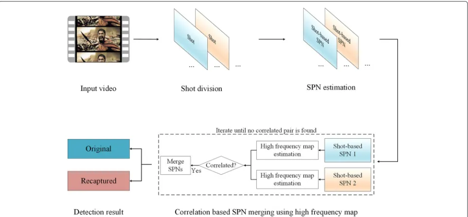
4 Proposed method
In this section, the recaptured video detection method is described in detail. Figure 2 depicts the proposed method, which is divided into three steps. First, the input video is divided into shots in the shot division step. Then, the shot-based SPNs are estimated from the divided shots. Finally, the input video is determined to be a recaptured video or an original video using correlation-based SPN merging. In the last step, each pixel in the estimated SPN is examined using a high-frequency map (HFM) to exclude the high-frequency components from the estimated SPN.
4.1 Shot division
Once an input video is selected, it is divided into mul-tiple shots using the shot change detector. An accurate shot change detector is important because incorrect shot change declarations can affect the results of the proposed method. Figure 3 depicts two different shot change detec-tion errors in original videos. If a shot change is missed, as depicted in Fig. 3a, two actual successive shots are declared to be a single shot. The declared shot in Fig. 3a might have two different source camcorders. It results in a mixture of two SPNs and it can be correlated to any SPN that is estimated from a shot recorded by the source camcorders of those shots. As a result, it increases the false positive ratio (FPR) in the calculation of the SPN cor-relation. In contrast, the false shot change alarm in the original video does not have an enormous effect on the result of the proposed method. The actual single shot is divided into two different shots in Fig. 3b. It only increases the count of the correlation calculation and shortens the length of the falsely divided shots. In addition, a wrong shot change declaration in the recaptured video does not have an enormous effect on the result of the proposed method because every shot in the recaptured video is assumed to be recorded by an identical digital camcorder. Therefore, the performance of the shot change detector needs to be tuned in order to minimize the missed shot changes.
From the various shot detection techniques available, the histogram comparison is used. The histogram com-parison is discriminant, easy to compute, and mostly insensitive to translational, rotational, and zooming shots [16, 20]. In the proposed method, two detectors (one for intensity and the other for hue) are used in order to min-imize the missed shot changes. The detail of the shot change detectors is described as follows:
SDp=
G−1
q=0
|Hp(q)−Hp+1(q)|, (6)
Fig. 2An overview of the proposed recaptured video detection method
possible levels of the histogram.SDp, which is the criterion for the shot change, is the sum of the absolute differences between the histograms derived from thepth frame and the (p+1)th frame. In order to utilizeSDpfor shot change detection with any frame size,SDpis normalized using the frame size. If the normalizedSDpis greater than a given threshold, the shot change is declared. As a result, the con-secutive frames between two successive shot changes are declared as one shot.
4.2 SPN estimation
In this step, the shot-based SPN is estimated from each shot. Before the estimation, inappropriate shots for the estimation including dark shots and short-length shots are excluded. Each shot-based SPN is estimated using the maximum likelihood estimation method based on the SPN model [18, 19]. Assuming that the shot is composed of d grayscale frames (I1,I2,. . .,Id), the detailed SPN estimation process is as follows:
K=
d
n=1WnIˆn d
n=1(ˆIn)2
, (7)
whereK,Wn, andˆInrepresent the estimated SPN, a noise frame and a noiseless frame that correspond to the nth frame In, respectively. Each noise frame, which is used in the SPN estimation, is obtained by filtering the frame using a wavelet-based Wiener filter [21]. After the SPN estimation, the codec noise that is generated by the video codec is removed. Normally, the videos are transformed using the differential pulse-code modulation block dis-crete cosine transform and it produces block artifacts in each video frame [19]. These block artifacts should be removed prior to the correlation calculation between estimated shot-based SPNs because they make uncorre-lated pairs of SPNs correuncorre-lated. These artifacts are periodic with a 16×16 block size and have a high energy in the frequency domain. They are removed using the Wiener filter in the frequency domain after zeroing out the means of rows and columns of the estimated shot-based SPN [18, 19]. The codec noise-free SPN is denoted bySPN.
4.3 Correlation-based SPN merging using high-frequency map
In this step, every shot-based SPN, which was estimated in the previous step, is examined to make the final decision.
(a)
(b)
However, each estimated shot-based SPN is low in quality so that the wrong decision might be driven at the decision-making step. To resolve the low-quality problem of the estimated shot-based SPN, Warshall’s algorithm was used in Jung et al.’s method [14]. However, Warshall’s algorithm only helped the erroneously uncorrelated shot-based SPN pairs to be linked to each other. Furthermore, none of the techniques that enhanced the quality of the estimated SPN was used.
In the proposed method, correlation-based SPN merg-ing and a HFM are used to resolve the low-quality prob-lem of the estimated shot-based SPN. A better quality of SPN, which minimizes the false decisions of the pro-posed method, can be obtained using correlation-based SPN merging. Furthermore, HFM helps to remove the regions that might have a detrimental effect on the SPN merging and the correlation calculation.
4.3.1 High-frequency map (HFM)
The estimated shot-based SPNs are investigated to deter-mine whether they are correlated with each other using correlation-based SPN merging. However, estimated shot-based SPNs have low quality. The low quality of the estimated SPN influences the correlation calculation and SPN merging. If SPNi is the shot-based SPN estimated from theith shotShoti(i=1,. . .,NS), then it is expressed as follows:
SPNi=SPNi+i, (8)
where SPNi andi denote the ideal SPN and the com-posite error, which is caused during the SPN estimation process, corresponding to SPNi, respectively. The lower energy ofiresults in better quality ofSPNi; furthermore, the lower variance of the sequencei[x,y] for each pixel (x,y) provides the better quality of the merged SPN. Thus, both a better quality of the merged SPN and a low false negative correlation can be achieved if high-energy regions ini are suppressed. High-energy regions in i are typically introduced by high-frequency components such as the strong edges in the video frames. Therefore, the high-frequency components need to be excluded from the estimated SPN. If only the high-quality regions in the SPNs are selected before the SPN merging, high quality of the merged SPN is guaranteed.
Li proposed an approach to attenuating the influ-ence of the high-frequency components on the estimated SPNs [22]. Li’s method improved the accuracy of the source camera identification by assigning weighting fac-tors inversely proportional to the magnitude of the test SPN components. However, this method was designed for the source digital camera identification using fine qual-ity of reference SPN. Furthermore, two different SPNs still can be correlated after Li’s method is applied if they
have correlated high-frequency components in the same position.
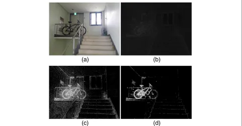
Based on the above observation, we propose a HFM, which is a Boolean matrix that has the same frame size as the estimated SPN, to determine whether any pixel of the estimated SPN is contaminated by a high-frequency component. The high-high-frequency components in the scene leave relatively high absolute pixel values because denoising filters are applied in the noise estima-tion. Figure 4 depicts the histogram difference caused by high-frequency components. Figure 4a, which is a his-togram that is calculated from each pixel value of a high-quality SPN, presents a small variance; Fig. 4b, which is a histogram that is calculated from each pixel value of a low-quality SPN contaminated by the high-frequency components, presents a relatively large variance. There-fore, high absolute values are filtered to remove the high-frequency components in the estimated SPN. How-ever, it is not desirable to set a fixed pixel threshold to remove high-valued pixels because the pixel values in the estimated SPN vary depending on the recording environ-ment. A normal distribution fitting is used to avoid the fixed thresholding. Afterward, the SPN is standardized using the mean and variance of the estimated normal dis-tribution model. Moreover, a certain portion of the HFM is marked by thresholding the standardized SPN. The HFM is calculated as follows:
HFM[x,y]=
1, SPNZ[x,y] > zα
0, SPNZ[x,y] ≤ zα , (9)
whereSPNZis the standardizedSPN using the estimated model andzα is the critical point of the standard normal distribution (1= high-frequency component, 0= clean SPN).
After the HFM is created, it is refined by removing the erroneously detected parts. Since high-frequency com-ponents are normally connected and grouped together, the connected pixel groups that are extremely small are pruned. The HFM is morphologically dilated and eroded, then the eight-way connected components with sized smaller than a specified percent (0.01 % in the proposed method) of the frame size are converted to zero.
The HFM indicates the high-frequency components so that the relative regions in the estimated SPN are removed using HFM, as follows:
SPN=SPN · ¬HFM, (10)
−5 −4 −3 −2 −1 0 1 2 3 4 5 x 10⁻³
0 0.5 1 1.5 2 2.5 3 3.5x 10
5
Values
Count
n vs. xout PRNU
(a)
−5 −4 −3 −2 −1 0 1 2 3 4 5
x 10−3
0 2 4 6 8 10 12 14x 10
4
Values
Count
n vs. xout PRNU
(b)
Fig. 4SPN histograms.aAn estimated high-quality SPN andban estimated SPN contaminated by high-frequency components
4.3.2 Correlation-based SPN merging
In order to determine whether a given video is recaptured or not, the estimated shot-based SPN is investigated. If
N shots are selected from the given video, thenN shot-based SPNs are estimated and the corresponding HFMs are applied. Let SPNi be a shot-based SPN estimated from the ith shot Shoti (i = 1,. . .,N). Two different shot-based SPNs shall be correlated if the correspond-ing shots are recorded by the identical digital camcorder. In order to verify this, the correlations between the esti-mated shot-based SPNs are measured. The correlation
betweenSPNi andSPNj (i = j) is measured by calculat-ing the peak-to-correlation energy (PCE) value between them. The PCE is described as follows:
PCE SPNi,SPNj=
Corr SPNi,SPNj[ucenter,vcenter]2
u,vCorr SPNi,SPNj[u,v]2
,
(11)
whereCorr(·,·)[u,v] represents the value of the normal-ized cross-correlation (NCC) surface that is calculated
(a)
(b)
(c)
(d)
between the SPN pair at the position of(u,v). The center coordinate of the correlation plane was used in the PCE calculation rather than using the peak coordinate because the coordinate offset of each shot is synchronized in the recaptured video, while it might not be in the original video. If the PCE value is greater than a given thresh-old T, then two shotsShoti andShotj are determined to have been recorded using the identical digital camcorder. Otherwise,Shoti andShotjare determined to have been recorded using two different digital camcorders.
The input video is declared to be a recaptured video if every possible pair of the estimated shot-based SPNs presents greater PCE values than the thresholdT. How-ever, the low-quality problem of the estimated shot-based SPN still remains. The low quality of the estimated SPNs increases the false negative correlations. To minimize the false negative correlation, the correlation-based SPN merging is used. The SPN merging increases the number of frames in the SPN estimation of the merged SPN; and a large number of frames produce a small variance of the estimated SPN [17, 18].
The correlation-based SPN merging on a given shot-based SPN array is divided into 4 steps (refer to Fig. 2): (1) iterate steps 2 to 4 until the size of the shot-based SPN array does not change; (2) the HFM of each shot-based SPN is estimated; (3) the PCE value of every pair in the shot-based SPN array is calculated using HFM; (4-1) if a correlated pair is found, it is merged using HFM; (4-2) the shot-based SPN array is updated by replacing the correlated pair with the newly merged SPN.
In the SPN merging step, the HFMs are used. LetSPNi andSPNjbe merged intoSPNM, then each pixel inSPNM is computed as follows:
SPNM=
⎧ ⎪ ⎪ ⎨ ⎪ ⎪ ⎩
Ave(SPNi[x,y] ,SPNj[x,y]), HFMi[x,y]=0∧HFMj[x,y]=0
SPNj[x,y] , HFMi[x,y]=1∧HFMj[x,y]=0
SPNi[x,y] , HFMi[x,y]=0∧HFMj[x,y]=1
0, otherwise
,
(12)
whereAve(·,·),HFMi,HFMj,SPNi, andSPNjdenote an averaging operation based on the number of frames that are used in the SPN estimation (including SPN merg-ing), the HFMs and the high-frequency-component-free SPNs that correspond to SPNi and SPNj, respectively. The final decision is made after the correlation-based SPN merging process is finished. If the final output is a sin-gle merged SPN, then the input video is declared to be a recaptured video. Otherwise, the input video is declared to be an original video.
Finally, we analyze the computational complexity of the proposed method. Let Fs, NT, NTS, and NS denote the maximum value between the row and column sizes of a test video, the total length of the video frames, the
sum of the frame lengths of selected shots, and the num-ber of selected shots. The shot division step is processed in time O Fs2·NT
and the SPN estimation step is in timeO Fs2·NTS
+ O Fs2logFs·TS
by assuming that the size of the wavelet filter is negligible compared toFs [23]. Computing the NCC takes O Fs2logFs
by a fast Fourier transform; thus, the computational complexity of correlation-based SPN merging is O Fs2logFs·NS3
. SinceNT ≥TTS NS, the computational complexity of the proposed method can be expressed as below.
O Fs2logFs·NT
(13)
5 Experimental results
In this section, the performance of the proposed method is evaluated. The specific settings for the experiments are also provided. Furthermore, the results of the experiments are presented and analyzed.
5.1 Experiment settings
For the experiments, 130 original videos were used. Most of the videos were originally shot partially or com-pletely using digital camcorders [24]. The original video list includes Attack on Titan (TV animation), Game of
Thrones (season 3), Homeland (seasons 1 and 2), The
Office (season 7), andSherlock (seasons 1 and 2). Seven
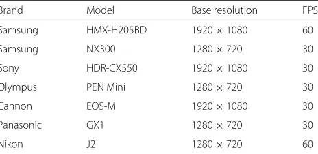
digital camcorders (refer to Table 1 for specifications) were used to recapture the original videos. In total, 400 videos were created via recapturing. The original videos with a resolution of 1280×720 were collected, and the video recaptures were conducted with the same resolution conditions. In the high-definition (HD) resolution videos, the robustness of the proposed method was tested at dif-ferent video quality factors (QFs) and scaling factors (SFs). The recaptured videos were recompressed with QFs of 100, 90, 80, 70, and 60. In addition, they were resized with SFs of 80 and 60 and recompressed with QFs of 100 and 80. As a result, a total of 3600 recaptured videos were cre-ated for the experiments. In the shot division step, the 20 longest shots (NS=20) were selected from each test video for the SPN estimation step. Each selected shot had more
Table 1Specifications of the cameras used in the experiments
Brand Model Base resolution FPS
Samsung HMX-H205BD 1920×1080 60
Samsung NX300 1280×720 30
Sony HDR-CX550 1920×1080 30
Olympus PEN Mini 1280×720 30
Cannon EOS-M 1920×1080 30
Panasonic GX1 1280×720 30
than 100 frames in general and the average shot length of the selected shots was approximately 130.
An auditorium was selected for the video recapturing. The auditorium was approximately 18 m wide and 21 m long, and it had 286 fixed seats. The width of the screen in the auditorium was approximately 4m, and the video clips projected using an NEC PA600X projector on the screen were displayed at a size of 4×2.25 m in the hor-izontal and vertical directions, respectively. Because the auditorium had its own slope between the seating rows and the zooming of the digital camcorders was restricted, four seats, which are indicated using red dashed circles in Fig. 6, were selected for the recapturing in order to have the entire projected video screen within the camera angle. Furthermore, every light source (except the beam projec-tor) was blocked in order to simulate a movie theater; thus, the average luminance was 0.2 LUX while the recaptur-ing was conducted. The camcorders were also mounted on tripods for the recapturing.
In the experiments, several modified decision-making measures of the SPN merging were tested. The proposed SPN merging uses a strict criteria that declares a detection only if a single merged SPN remains after the SPN merging iterations stop. However, two or more SPNs will remain if one or more shot-based SPNs that have extremely low quality are included. In order to take this case into account, the modified measures that tolerate remaining
k additional SPNs, which were never merged, except a single merged SPN. Three different k values (0 original criteria, 1, and 2) were used in the tests. Furthermore, in order to demonstrate the performance of the proposed
method, it was compared with two recaptured image detection methods (Cao and Kot’s method [9], Gao et al.’s method [10]) and three recaptured video detection methods (Wang and Farid’s method [11], Bestagini et al.’s method [13], and Jung et al.’s method [14]). In order to apply the recaptured image detection methods to the obtained videos, every I frame was extracted from theNS shots that were used in testing the proposed method. We randomly selected 80 % of the extracted frames for train-ing and the remaintrain-ing for testtrain-ing. Furthermore, thoseNS shots were used to examine the above listed recaptured video detection methods. The parameters for Wang and Farid’s method were set as follows: the number of points for feature matching was 32 and the number of fundamen-tal matrices for skew estimation was 5. In Bestagini et al.’s method, two detectors for two different video recording environments were proposed. Therefore, the detector that fits our test environment (video frame rate=camcorder frame rate) was tested.
5.2 HFM experiment
To evaluate the performance of the proposed HFM, we conducted an experiment. The PCE values that were cal-culated from each pair of the shot-based SPNs were ana-lyzed. Since 20 shots were selected from each test video, 190 PCE values were calculated per a test video. In this test, six values (0.0005, 0.001, 0.005, 0.01, 0.05, and 0.1) were used forα, which is the parameter of the HFM. Fur-thermore, Li’s method [22] was benchmarked. Model 5, which presented the best results in source digital cam-era identification, was used in the experiment. Figure 7
Fig. 7The 1.5 IQR of the HFM test (the PCE values were calculated from pairs of SPNs)
presents the PCE values from both the original video and the recaptured video (including the recompressed and scaled video) using 1.5 interquartile range (IQR) boxplots. As Fig. 7 describes, a wide overlapping range was exhib-ited in the PCE values between the original video and the recaptured video when no post-processing was applied. The overlapping range caused a significant number of false positive SPN correlations. However, the overlapping range was significantly narrowed after the techniques that degrade the influence of the high-frequency components were applied. This indicates that the number of false posi-tive SPN correlations decreased. Li’s method was effecposi-tive in attenuating the influence of high-frequency compo-nents. However, the attenuation in the pixel values of the high-frequency components still creates a false positive correlation. Since the proposed HFM changes the pixel values with the high-frequency components to zero, the range of the overlap is narrower than that of Li’s method. The increment ofαvalue did not have a significant effect on the test results because the majority of the detected pixels in the HFM was filtered by post-processing. The range of the overlap was minimized where α was 0.005. Therefore, we used 0.005 for the HFM parameterαin the following experiments. Furthermore, Li’s method was not
tested in the rest of the experiments because Li’s method cannot be applied to SPN merging.
5.3 Quality factor experiment
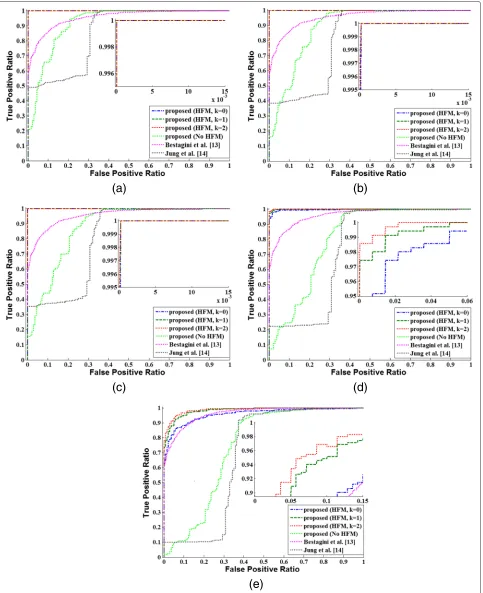
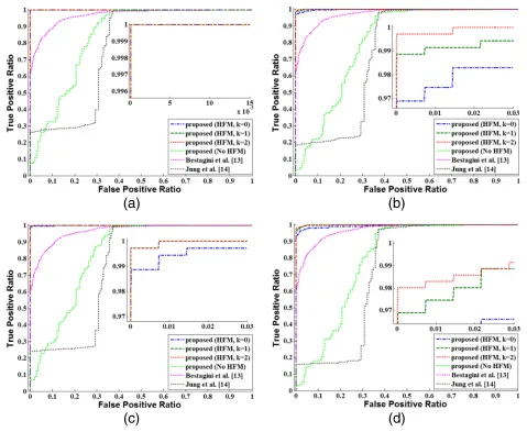
In general, the recaptured videos are recompressed in order to reduce their file size before the online distribution. For this reason, we tested the robustness to compression. The recaptured videos were compressed using various quality factors (QFs) while other compres-sion attributes, including the resolution and frame rate, were not changed. The range of QFs for the test was set from QF100 to QF60 with a step size of 10. The ffdshow H.264 codec and TMPGEnc 4.0 Xpress video encoder were used to recompress the test videos. In addition, we used the variable key frame interval, which was the default setting. The parameterαof the HFM was set to 0.005.
(a)
(b)
(c)
(d)
decreased. However, the detection results were not satis-factory. The frame rate change, which was used to unite various shots in the original video production, might have produced false positive detection. The proposed method without the HFM produced slightly better results than Jung et al.’s; however, it also did not provide satisfactory detection results. In contrast, the proposed method with the HFM exhibited a high level of detection ratios. Overall, the every recaptured video detection method that utilized the SPN exhibited a decreasing detection ratio as the QF decreased.
The recompression lowers the quality of the estimated shot-based SPN and results in low correlation values between the shot-based SPNs. Furthermore, the severe quality degradation of the shot-based SPN disturbs the SPN merging and makes the shot-based SPN uncorre-lated even to the high-quality SPN. In the high QF tests (Fig. 8a–c) with the strict criteria (k = 0), most missed detections resulted from the low correlations between the merged SPN and several shot-based SPNs that had the severely degraded quality due to the recompression. How-ever, with a less strict criteria (k=1, 2), the detection ratio increased because the number of the shots that under-went the severe quality degradation was small. In contrast, in the low QF tests (Fig. 8d–e), most missed detections arose from the failure of the SPN merging because the quality of most of the estimated shot-based SPNs was heavily degraded. The proposed method presented a low detection ratio in the QF60 test. However, in general, QF60 is not a common quality factor that is used in video compression due to the severe visual quality degradation. Thus, the low detection ratio in the QF60 test is acceptable considering that QF60 is a rare compression parameter for recaptured videos.
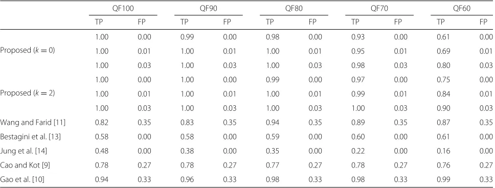
Table 2 presents the test results for Cao and Kot’s method, Gao et al.’s method, and Wang and Farid’s
method. The test results of these methods could not be presented in graph form; thus, we compared the proposed method by fixing the false positive ratio. In addition, we also included the test results for Bestagini et al.’s method and Jung et al.’s method at a zero false positive ratio. The table demonstrates that the proposed method out-performed the other methods, except in the QF60 test where Gao et al.’s method outperformed the proposed method.
5.4 Scaling factor experiment
The recaptured videos were scaled using various scaling factors (SFs). Because up-scaling is rare for videos, only SFs lower than 100 (%) were tested. SFs lower than 60 were excluded in the experiment considering that the res-olution of the original recaptured videos was 1280×720. Normally, the video quality is also adjusted when the scal-ing is adjusted; thus, the experiments for QF80, which is a common default recompression quality factor, were also conducted.
The detailed settings of recompression followed the quality factor experiment except for the QF and SF. Figure 9 presents the experiment results for the scaled test videos. The proposed method (k = 2) with the HFM outperformed the other methods. The proposed method exhibited good results for QF80 and SF0.8, which are common parameters for video scaling. Table 3 presents the test results compared with Cao and Kot’s method, Gao et al.’s method, Wang and Farid’s method, Bestagini et al.’s method, and Jung et al.’s method. The table demonstrates that the proposed method out-performed the other methods at every SF level. The compared methods that did not utilize the SPN exhib-ited a constant detection ratio while the QF and SF decreased.
Table 2Detection result at different levels of video quality factors
QF100 QF90 QF80 QF70 QF60
TP FP TP FP TP FP TP FP TP FP
Proposed (k=0)
1.00 0.00 0.99 0.00 0.98 0.00 0.93 0.00 0.61 0.00
1.00 0.01 1.00 0.01 1.00 0.01 0.95 0.01 0.69 0.01
1.00 0.03 1.00 0.03 1.00 0.03 0.98 0.03 0.80 0.03
Proposed (k=2)
1.00 0.00 1.00 0.00 0.99 0.00 0.97 0.00 0.75 0.00
1.00 0.01 1.00 0.01 1.00 0.01 0.99 0.01 0.84 0.01
1.00 0.03 1.00 0.03 1.00 0.03 1.00 0.03 0.90 0.03
Wang and Farid [11] 0.82 0.35 0.83 0.35 0.94 0.35 0.89 0.35 0.87 0.35
Bestagini et al. [13] 0.58 0.00 0.58 0.00 0.59 0.00 0.60 0.00 0.61 0.00
Jung et al. [14] 0.48 0.00 0.38 0.00 0.35 0.00 0.22 0.00 0.16 0.00
Cao and Kot [9] 0.78 0.27 0.78 0.27 0.77 0.27 0.78 0.27 0.76 0.27
Gao et al. [10] 0.94 0.33 0.96 0.33 0.98 0.33 0.98 0.33 0.99 0.33
(a)
(b)
(c)
(d)
Fig. 9Scaling factor experiment results.aSF80,bSF60,cSF80 with QF80, anddSF80 with QF80
Table 3Detection result at different levels of scaling factors
SF80 SF80 (QF80) SF60 SF60 (QF80)
TP FP TP FP TP FP TP FP
Proposed (k=0)
0.99 0.00 0.95 0.00 0.98 0.00 0.92 0.00
1.00 0.01 0.97 0.01 0.99 0.01 0.94 0.01
1.00 0.03 0.98 0.03 1.00 0.03 0.97 0.03
Proposed (k=2)
1.00 0.00 0.99 0.00 1.00 0.00 0.96 0.00
1.00 0.01 1.00 0.01 1.00 0.01 0.98 0.01
1.00 0.03 1.00 0.03 1.00 0.03 0.99 0.03
Wang and Farid [11] 0.84 0.35 0.86 0.35 0.86 0.35 0.92 0.35
Bestagini et al. [13] 0.61 0.00 0.60 0.00 0.62 0.00 0.61 0.00
Jung et al. [14] 0.26 0.00 0.23 0.00 0.18 0.00 0.16 0.00
Cao and Kot [9] 0.77 0.27 0.78 0.27 0.78 0.27 0.78 0.27
Gao et al. [10] 0.98 0.32 0.97 0.32 0.98 0.33 0.97 0.33
6 Conclusions
This paper investigated a recaptured video detection method. The proposed method operates automatically for a given video and does not use additional information such as watermarks. The proposed method is based on the SPN, which is the unique fingerprint of digital imag-ing sensors. The proposed method consists of three steps: first, the video is divided into shots; second, the shot-based SPN is estimated from the divided shots; and third, the video is determined to be a recaptured video or not using the correlation-based SPN merging. Furthermore, an HFM was used to exclude the low-quality regions in the estimated SPNs during the SPN correlation calculation and merging processes. We demonstrated the superior performance of the proposed method by comparing the test results for various quality factors and scaling factors with other recaptured content detection methods. How-ever, the proposed method remains weak against severe video compression. The next research focus will include considerations of this weakness.
Competing interests
The authors declare that they have no competing interests.
Acknowledgements
This research project was supported by Ministry of Culture, Sports and Tourism (MCST) and from Korea Copyright Commission in 2015.
Received: 16 December 2014 Accepted: 26 November 2015
References
1. Motion Picture Association of America. http://www.mpaa.org. Accessed 2 Dec 2015
2. M-J Lee, K-S Kim, H-K Lee, Digital cinema watermarking for estimating the position of the pirate. IEEE Trans. Multimed.12(7), 605–621 (2010) 3. M Celik, J Talstra, A Lemma, S Katzenbeisser, inIEEE International
Conference on Image Processing. Camcorder capture robust
low-complexity watermarking of mpeg-2 bit-streams, vol. 5 (IEEE, 2007), p. 489
4. D Delannay, J-F Delaigle, BM Macq, M Barlaud, inProceedings of Electronic Imaging. Compensation of geometrical deformations for watermark extraction in digital cinema application, vol. 4314 (SPIE, San Jose, CA, 2001), pp. 149–157
5. A van Leest, J Haitsma, T Kalker, inProceedings of Electronic Imaging. On digital cinema and watermarking, vol. 5020 (SPIE, Santa Clara, 2003), pp. 526–535
6. T Yamada, S Gohshi, I Echizen, inIEEE International Conference on Image Processing. Preventing re-recording based on difference between sensory perceptions of humans and devices (ICIP, Hong Kong, 2010), pp. 993–996 7. T Yamada, S Gohshi, I Echizen, inDigital Forensics and Watermarking, 10th
International Workshop, IWDW 2011, LNCS 7128. Ir hiding: method to prevent re-recording screen image built in short wavelength pass filter detection method using specular reflection (Springer, Atlantic City, NJ, USA, 2012), pp. 111–125
8. T Yamada, S Gohshi, I Echizen, inIEEE International Conference on Image Processing. Countermeasure of re-recording prevention against attack with short wavelength pass filter (ICIP, Belgium, 2011), pp. 2753–2756 9. H Cao, AC Kot, inProceedings of the IEEE International Conference on
Acoustics, Speech, and Signal Processing. Identification of recaptured photographs on lcd screens (ICASSP, Dallas, Tex, USA, 2010), pp. 1790–1793
10. X Gao, T-T Ng, B Qiu, S-F Chang, inProceedings of the IEEE International Conference on Multimedia and Expo. Single-view recaptured image
detection based on physics-based features (ICME, Singapore, 2010), pp. 1469–1474
11. W Wang, H Farid, inInformation Hiding, Lecture Notes in Computer Science. Detecting re-projected video (Springer, Berlin, 2008), pp. 72–86 12. M Visentini-Scarzanella, PL Dragotti, inIEEE 14th international Workshop on
Multimedia Signal Processing. Video jitter analysis for automatic bootleg detection (MMSP, Canada, 2012), pp. 101–106
13. P Bestagini, MV Scarzanella, M Tagliasacchi, PL Dragotti, S Tubaro, inIEEE International Conference on Image Processing. Video recapture detection based on ghosting artifact analysis (ICIP, Melbourne, Australia, 2013), pp. 4457–4461
14. D-J Jung, D-K Hyun, S-J Ryu, J-W Lee, H-Y Lee, H-K Lee, inDigital Forensics and Watermarking, 10th International Workshop, IWDW 2011, LNCS 7128. Detecting re-captured videos using shot-based photo response non-uniformity (Springer, Atlantic City, NJ, USA, 2012), pp. 281–291 15. S Warshall, A theorem on boolean matrices. J. ACM.9, 11–12 (1992) 16. C Cotsaces, N Nikolaidis, I Pitas, Video shot detection and condensed
representation. a review. IEEE Signal Proc. Mag.23(2), 28–37 (2006) 17. J Lukas, J Fridrich, M Goljan, Digital camera identification from sensor
pattern noise. IEEE Trans. Inf. Forensics and Security.1(2), 205–214 (2006) 18. M Chen, J Fridrich, M Goljan, inProceedings of SPIE Electronic Imaging,
Security, Steganography, Watermarking of Multimedia Contents IX. Digital imaging sensor identification (further study), vol. 6505 (International Society for Optics and Photonics, San Jose, California, 2007), pp. 65050–65050
19. M Chen, J Fridrich, M Goljan, J Lukáš, inProceedings of SPIE Electronic Imaging, Security, Steganography, Watermarking of Multimedia Contents IX. Source digital camcorder identification using sensor photo response non-uniformity, vol. 6505 (International Society for Optics and Photonics, San Jose, California, 2007), pp. 65051–65051
20. H Zhang, A Kankanhalli, SW Smoliar, Automatic partitioning of full-motion video. Multimedia systems.1(1), 10–28 (1993)
21. MK Mıhçak, I Kozintsev, K Ramchandran, inProceedings of the IEEE International Conference on Acoustics, Speech, and Signal Processing. Spatially adaptive statistical modeling of wavelet image coefficients and its application to denoising, vol. 6 (ICASSP, 1999), pp. 3253–3256 22. C-T Li, Source camera identification using enhanced sensor pattern noise.
IEEE Trans. Inf. Forensics and Security.5(2), 280–287 (2010) 23. AC Bovik,Handbook of Image and Video Processing. (Academic press,
Austin, Texas, 2010)
24. The Internet Movie Database. http://www.imdb.com. Accessed 2 Dec 2015
Submit your manuscript to a
journal and benefi t from:
7Convenient online submission
7Rigorous peer review
7Immediate publication on acceptance
7Open access: articles freely available online
7High visibility within the fi eld
7Retaining the copyright to your article