International Journal of Emerging Technology and Advanced Engineering
Website: www.ijetae.com (ISSN 2250-2459,ISO 9001:2008 Certified Journal, Volume 4, Issue 7, July 2014)
918
Video Compression Using Hybrid DWT-DCT Algorithm
L. Escalin Tresa
1, Dr. M. Sundararajan
21Research Scholar, Sathyabama University, Chennai 2Principal, Alpha College of Engineering & Technology, Puducherry Abstract- Videos and images are one of the most important
approaches to represent some data. Now a day’s all the communication process are working on such media. The main problem with this kind of media is its large size. Also this large data contains a lot of redundant information. Compressing the video helps to reduce the size and thus saves the transmission bandwidth and storage space. By considering the role played by image and video in communication it is necessary to develop a compression scheme that can achieve a high compression ratio while preserving the video quality. DWT (Discrete Wavelet Transform) and DCT (Discrete Cosine Transform) are the most commonly video compression techniques. DCT has high energy compaction and requires less computational resources, DWT on the other hand is a multiresolution transformation. But the compression ratio that can be achieved is low. The proposed method uses a Hybrid DWT-DCT algorithm on motion compensated frame by taking the advantages of both the method. The performance of the proposed method can be evaluated using compression ratio, PSNR and mean square error.
Keywords - Compression, Discrete cosine transform, Discrete wavelet transform, Motion compensation, Motion estimation.
I. INTRODUCTION
Video has been an essential part of entertainment and communication now a day. But it requires a large amount of storage space and transmission bandwidth. For example a movie of 90 minutes of 30 frames per second frame rate and resolution of 750*570 will require 2.78 GB. The storage and bandwidth requirement of this uncompressed movie is very high. If this can be compressed to a size of certain MB’s the storage requirements can be reduced to a great extent. Video compression helps in achieving this without affecting the quality of the video. Videos and images contain a large amount of redundant information. The main technique of video compression relies in discarding this redundant information to which the human eyes are insensitive. While compressing the video there is a tradeoff between the video quality and the amount of compression achieved [1]. If the compression achieved is high the quality of the reconstructed video is low. Also the latency in compressing the video should be considered. Thus a good compression scheme aims in obtaining a better compression while considering the all the parameters.
Discrete cosine transforms (DCT) and discrete wavelet transform (DWT) are the most commonly used methods for video compression. DCT has high energy compaction and requires less computational resources, DWT on the other hand is a multiresolution transformation. But the compression ratio that can be achieved is low. A hybrid method by combining DWT and DCT can achieve a better result than individually applying the two methods. Most of the existing DCT based and DWT based codec’s achieve a low compression ratio, and the computation time is more. On the other hand the hybrid approach has shown much better results in terms of compression ratio, latency, PSNR and the quality of the reconstructed frame.
II.TRANSFORM METHODS
A. Discrete Wavelet Transform
The wavelet transform of a signal gives its time frequency representation. On the wavelet transform which was developed to overcome the shortcomings of the short time Fourier transform (STFT) is a multiresolution transformation. This property of the Fourier transform helps to analyse different frequencies of signals at different resolutions. In contrast to a wave which is an oscillating function of time or space the wavelets are localized waves and are non periodic [2]. The energy of the wavelets is concentrated in time or space.
B. Discrete Cosine Transform
International Journal of Emerging Technology and Advanced Engineering
Website: www.ijetae.com (ISSN 2250-2459,ISO 9001:2008 Certified Journal, Volume 4, Issue 7, July 2014)
919
C. Hybrid DWT – DCT Transform
The Hybrid DWT-DCT transform exploits the properties of both the DWT and DCT techniques and provides a better compression. The input frame obtained from the video is first converted into 32*32 blocks. Each block is then transformed individually. The 32*32 block is converted into 16*16 after one level dwt and discarding all the coefficients except the LL (i.e. LH, HH, and HL). The second level of the 2 dimensional DWT is applied on the retained LL coefficients. And this yields an 8*8 block after discarding all the LH, HH, HL coefficients and preserving only LL. The DCT is applied on this block. After the transformation by DCT, quantization is applied on the DCT coefficients which rounds off the high frequency components to zero [4]. The reconstruction can be performed by the reverse process i.e. first the inverse quantization is done and then the IDCT is performed which yields an 8*8 block. The first level IDWT gives a16*16 blocks and the second level of IDWT gives the 32*32 block. This process is applied for the entire image.
III. THE PROPOSED VIDEO CODEC
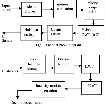
The proposed algorithm aims to achieve a high compression ratio with less latency while preserving the original video quality by optimizing the available methods for video compression. A tradeoff between the different performance parameters is to be considered. The block diagrams of the proposed encoder and the decoder are given below fig.
Input Video
[image:2.612.44.267.482.703.2]
Bit Streams
Fig 1. Encoder block diagram
Bitstreams
Decompressed frame
Fig 2. Decoder block diagram
A. Encoder
The input video of any format is converted into frames. The resolution of the frames is converted into 782*582 and the format is .bmp. The frames are processed one after the other. For the intra frame (first frame) motion estimation and compensation are not performed. They are transformed by hybrid DWT-DCT transform and are reconstructed back by the inbuilt decoder at the encoder and are stored in the memory. From the second frame onwards (inter frames) the motion estimation and compensation is performed. The motion estimation is done by the adaptive rood pattern search algorithm by finding the difference between the current and the reference frames and then the second frame is predicted from the first frame and then the error frame between the first and the second frame is generated. The transform for the inter frames is applied to these kind of error frames generated. After quantization these frames are entropy coded with Huffman coding and the generated bit streams are transmitted to the decoder side. The size of the compressed frame is and thus there is a saving in the storage space.
B. Decoder
The encoded bit stream is first inverse variable length coded and then the decoded bit streams are first inverse cosine transformed and further inverse wavelet transformation is applied to the obtained coefficients. To this decompressed image, intensity motion compensation is applied. The motion compensation performed at the encoder side removes the high intensity pixels in the image and these are reconstructed at this decoder stage. The intensity motion compensated image has a better visual quality than the decompressed image.
IV. PERFORMANCE CRITERION
A. Compression ratio
The reduction in the size of data due to the compression is given by compression ratio [5]. Space savings obtained by compression can be also shown by compression ratio.
CR= Discarded Data / Original Data
B. Peak signal to noise ratio (PSNR)
PSNR is the ratio between the powers of the reconstructed image to that of the noise in the image. It is used to measure the quality of the reconstructed image. It is given by
(3)
Where MSE is mean square error
International Journal of Emerging Technology and Advanced Engineering
Website: www.ijetae.com (ISSN 2250-2459,ISO 9001:2008 Certified Journal, Volume 4, Issue 7, July 2014)
920
C. Mean square error (MSE)
MSE measures the average of the squared error in the reconstructed image [6]. It is the difference between the square of the original and the reconstructed image.
∑
∑ (4)
V. SIMULATION RESULTS
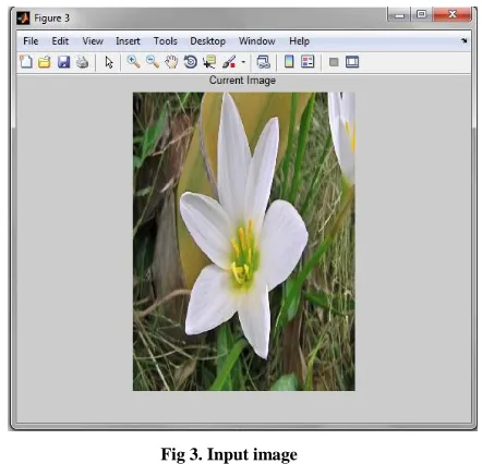
[image:3.612.334.554.130.343.2]One of the input frames from the video is shown in figure 3.
Fig 3. Input image
[image:3.612.63.284.264.477.2]The input frame i.e. the current frame is compared with the reference frame and the motion estimation is performed on these frames. This process yields the motion vector. The motion vectors are used for the compensation to yield the predicted frames. The rest of the process functions on these predicted frames. The motion compensated frame is shown in figure 4.
Fig 4. Motion compensated frame
After the motion compensation, the wavelet transform is applied on the predicted frame. Here one level and two level dimensional wavelet transform is used and the filter used is biorthogonal. The wavelet transformed frame is shown in figure 5.
[image:3.612.335.553.414.612.2]International Journal of Emerging Technology and Advanced Engineering
Website: www.ijetae.com (ISSN 2250-2459,ISO 9001:2008 Certified Journal, Volume 4, Issue 7, July 2014)
921
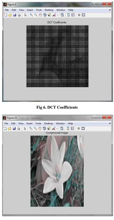
[image:4.612.334.553.183.577.2]After the wavelet transform, cosine transformation is applied on the wavelet transformed frame. The DCT coefficients are shown in figure 6. After the hybrid transform, the quantization is performed and then the entropy coding is done. The compressed frame is shown in figure 7.
Fig 6. DCT Coefficients
Fig 7. Hybrid DWT DCT compressed frame
After the compression, the process is reversed for decoding. First the inverse VLC and then dequantization is performed. Then the IDCT is applied and then the IDWT is performed. The decompressed frame obtained is shown in figure 8.
The motion compensation at the encoder results in loss of some intensity which is regained at the decoder through intensity based motion compensation. The intensity based motion compensated frame is shown in figure 9.
[image:4.612.57.279.207.636.2]Fig 8. Decompressed frame
Fig 9. Intensity motion compensation applied to decompressed frame
VI. CONCLUSION
[image:4.612.334.553.391.604.2]International Journal of Emerging Technology and Advanced Engineering
Website: www.ijetae.com (ISSN 2250-2459,ISO 9001:2008 Certified Journal, Volume 4, Issue 7, July 2014)
922
Wavelet decomposition is applied to the compensated image and DCT is applied further to this frame. The hybrid compressed frame is quantized and entropy coded with Huffman coding. The encoded bit stream is first inverse Huffman coded and IDCT transformed. It is further IDWT transformed and intensity compensated. It gives a high compression ratio and gives a better reconstructed quality.
REFERENCES
[1] Thazni Aziz, D. Raveena Judie Dolly Motion Estimation and Motion Compensated Video Compression Using DCT And DWT, International Journal of Emerging Technology and Advanced Engineering,(ISSN 2250-2459, ISO 9001:2008 Certified Journal, Volume 2, Issue 12, December 2012).
[2] Kohtaro Asai, Tokumichi Murakami, Shuichi Yamagishi, Akira Minezawa, Yusuke Itani, “New Video Coding Scheme Optimized for High-Resolution Video Sources”, IEEE journal of selected topics in signal processing, Vol. 5, No. 7, November 2011.
[3] Mayank Nema, Lalita Gupta, N.R. Trivedi , ”Video Compression using SPIHT and SWT Wavelet”, International Journal of Electronics and Communication Engineering. Volume 5, Number 1 (2012).
[4] Dishant Khosla, Amandeep Kaur, ”Design of Hybrid Compression Model using DWT-DCT-HUFFMAN Algorithms for Compression of Bit Stream”,International Journal of Engineering Research & Technology (IJERT) Vol. 1 Issue 5, July – 201.2
[5] MuzhirShaban, Al-Ani1andTalal Ali Hammour, ” Video Compression Algorithm Based on Frame Difference Approaches”,International Journal on Soft Computing ( IJSC ) Vol.2, No.4, November 2011.