2018 International Conference on Computer, Communications and Mechatronics Engineering (CCME 2018) ISBN: 978-1-60595-611-4
Joint Power and Bit-rate Allocation for Multi-carrier Wireless
Bidirectional Relaying Systems
Xiao-dong JI
*School of Electronics and Information, Nantong University, Nantong, China, 2260192, Nantong
Research Institute for Advanced Communication Technologies, Nantong China, 226019
*Corresponding author
Keywords: Power allocation, Bit-rate allocation, Wireless bidirectional relaying, Multi-carrier.
Abstract. This paper studied a power and bit-rate allocation optimization problem of a multi-carrier wireless bidirectional relaying system with the aim of minimizing the total transmit-power of the system. By using channel knowledge at the transmitters, the optimization problem was solved analytically, resulting in a joint power and bit-rate allocation algorithm. Simulation results confirmed the effectiveness of the proposed algorithm. It is shown that with the proposed power and bit-rate allocation algorithm, the total transmit-power of the system can be significantly reduced in contrast to the compared schemes.
Introduction
Recently, the realization of energy efficient wireless communications has attracted lots of interest in the research community. As such, the power minimization problem (i.e., saving as much energy as possible) has become a hot research topic for wireless bidirectional relaying systems (WBRSs) [1]-[9].
By using the channel statistics, the authors of [1] proposed a transmit-power allocation algorithm with the aim of reducing the overall transmit-power of the WBRS having asymmetric traffic requirements. By exploiting the statistic channel knowledge at transmitters, a joint power allocation and relay location algorithm was developed in [2] to minimize the power consumption of an asymmetric WBRS and meanwhile ensure the require quality-of-service of the system. In [3], a hybrid unidirectional and bidirectional relaying scheme developed in [4] was extended to an orthogonal frequency division multiplexing (OFDM) modulated WBRS. Moreover, the study of energy efficiency and spectrum efficiency trade-off for WBRSs can be found in [5] and references therein. By using the instantaneous and statistical channel knowledge, the authors of [8] developed two optimal power adaptation algorithms with the aim of achieving energy efficiency, while satisfying the individual peak-power limit on each node and the quality-of-service requirement of the system.
[image:1.595.196.396.661.748.2]It should be noted that most of the existing studies as mentioned earlier focus only on the single-carrier systems. Thus, it is natural to question how to extend the proposed algorithms to multi-single-carrier systems? Do they need to be improved or they should be completely re-devised? So far, this issue has not been well studied and deserves a though investigation. In this paper, an OFDM modulated WBRS is
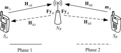
Figure 1. Wireless bidirectional relaying system model.
the system, and meanwhile allocating the end-to-end rates to different sub-carriers so as to reduce the overall transmit-power of the system, while ensuring the rate requirements of the two source nodes.
System Model
An OFDM modulated multi-carrier WBRS is considered, where each node is equipped with a single antenna and operates in a half-duplex style. Figure 1 presents the system model under investigation, where two source nodes SA and SB would like to send messages to each other with the help of an AF
relay node SR. Denote by Mi = [mi(1) , mi(2),· · ·, mi(T)] , i∈{A, B}, the OFDM symbol transmitted
by node Si, where T is the number of the sub-carriers that can be used, and mi(t) is the message send
by the source node Si on the t-th sub-carrier, t∈{1, 2, · · ·, T}. Denote by Pj = diag{pj(1), · · · ,
pj(T)}, j∈{A, B, R} the transmit-power at the source node Sj. The channel gain from node Si to node
Sj is denoted by Hij= diag{hij(1) , · · · , hij(T)}, i, j∈{A, B, R} and i≠j. Here, hij(t) is modeled as
ij ij
ij g d
h , where gij and dij denote the large-scale behavior and the distance, respectively, and α is
the corresponding path-loss coefficient. Without loss of generality, it is assumed that gij obeys CN(0,
1), and the channels are reciprocal, namely, Hij = Hji. Denote by wi, i∈{A, B, R}, the additive white
Gaussian noise (AWGN) at the node Si. It’s assumed that all the elements of the AWGNs obey i.i.d.
0,1
CN .
Figure 1 shows that one-round of communication between the two sources consists of two phases. During phase 1, the two source nodes SA and SB, respectively, send MA and MB to the relay SR.
During phase 2, the relay SR first scales each sub-carrier of the received signal by a factor F [3].
Next, the relay broadcasts the resulting signal to the two sources. At the end of phase 2, after decoding, the source Si can obtain the mutual information given by [3], [9]
2
1 1
1 log 1 2
T T
i i i
t t
I I t t
(1)where I ti and i t are the mutual information and the signal-to-noise ratio (SNR) for the
-th
t sub-carrier. Here, i t can be written as [3], [9]
2 2
2 2
1
j R AR BR
i
i R iR j jR
p t p t h t h t t
p t p t h t p t h t
(2) where t∈{1, 2, · · ·, T}.
Problem Description and Solution
The objective here is to develop a joint power and bit-rate allocation algorithm to reduce the total transmit-power of the system. Thus, a general optimization problem can be formulated as
* * * *
, , , 1
, , ,
arg min
A B R
A B R
T
A B R
p t p t p t t
t
p t p t p t t
p t p t p t
1 subject to
T
t
t
min IA,IB
(3) where is the end-to-end rate requirement of the two sources, t is the bit-rate allocated to the t
-th sub-carrier, and IA and IB are the mutual information obtained by the source nodes at the end of
For ease of solving the optimization problem, the solution is divided into two-stages. First, we study a per-sub-carrier optimization problem minimizing the system transmit-power. Next, a bit-rate allocation problem is studied so as to reduce the system transmit-power further. The per-sub-carrier optimization problem can be formulated as
, ,
, ,
arg min
A B R
c c c
A B R
A B R
p t p t p t
p t p t p t
p t p t p t
subject to minIA t ,IB t t
(4) where t is the bit-rate allocated to the t-th sub-carrier.
Proposition 1: The optimal solution of the per-sub-carrier optimization problem (4) can be given by
2
AR BR
c A
AR BR
t h t h t p t
h t h t
(5)
2
AR BR
c B
AR BR
t h t h t p t
h t h t
(6)
2
2 2
AR BR AR BR
c R
AR BR
t h t h t h t h t p t
h t h t
(7) where 2
2 t 1
t
.
Proof: Using the same methods proposed in our earlier works [1], [8] and [9], (5), (6) and (7) can be derived accordingly.
Based on the framework of the above per-sub-carrier optimization problem, we next address the problem of bit-rate allocation. The objective is to allocate the end-to-end rate of the two sources to all the used sub-carriers so as to reduce the total transmit-power further. The bit-rate allocation problem is formulated as
*
1 arg min
T
c c c
A B R
t t
t p t p t p t
1 subject to
T
t
t
t 0,t 1, 2, ,T
(8) where c
A
p t , c B
p t and c R
p t are the solution of problem (4) and give in (5), (6) and (7), respectively, is the end-to-end rate requirement of the two sources, and t is the bit-rate allocated to the t-th sub-carrier.
Proposition 2: Regardless of the last constraint of (8), the solution of problem (8) can be classified as the following two cases.
Case 1: t1 or tT. The solution is given by (9) or (10).
1
*
1 1
T
n
T n n
T T
1 * 1 T m m m T T T
(10) Case 2: t1, 2, ,T and t1,T. The solution is given by 1 1
*
1
t T
m n t
m m T n n t
T T T
. (11) Here, function t is defined as
2
1 1
= log
1 1 +
AR BR AR BR
AR BR AR BR
h t h t h t h t t
h t h t h t h t
. (12) Proof: The Lagrangian function of (8) without the last constraint is given by
2 2 2 2 1 1
2 2 t 1
T
AR BR AR BR
t
AR BR
T
t
h t h t h t h t
L
h t h t
k
where is a Lagrangian multiplier. Thus, the Karush–Khun–Tucker (KKT) conditions are formulated as 2 2 1 2 2 1
ln 2 2
0 0 t AR BR AR BR T t
h t h t
h t h t
t
(13) According to (13), it can be deduced that the optimal solution should satisfy (14) and (15), simultaneously. 1 0 T t t
(14) 2 2 1 2 2 2 2 1 12 2
ln 2 2
ln 2 2 1 1
1 1 t AR BR AR BR t AR BR AR BR
h t h t
h t h t
h t h t
h t h t
(15) Here, (14) and (15) can be rewritten as Xyv , namely,
1 1 0 0 0 0
1
0 1 1 0 0 0 1
2
0 0 1 1 0 0 2
3
0 0 0 0 1 0 1
0 0 0 0 1 1
1 1 1 1 1 1 1
T T
1
1 2 3 4 1 1
1 2 3 4 1 1
1 2 3 4 1 1
1 2 3 4 1 1
1 2 3 4 1 1
1 2 3 4 1 1
T T T T
T T T T T T
T T T
T T T T T T
T T
T T T T T T
T
T T T T T T
T T T T T T
T
T T T T T T
X
. Then according to 1
y X v, the final solution can be derived and is given in Proposition 2.
Remark: The solution presented in Proposition 2 is actually a solution of problem (8) without the last constraint. Since the allocated bit-rate for each sub-carrier must be larger than or equal to 0, the value of * t , t∈{1, 2, · · ·, T}, given in Proposition 2 should be checked. In case that * t given in Proposition 2 can satisfy the last constraint of (8), they are recognized as the final solution of problem (8). Otherwise, the sub-carrier with the minimum bit-rate will be discarded and the end-to-end rate of the two sources will be reallocated to the other sub-carriers until all the allocated bit-rates can satisfy the last constraint of (8).
Then, based on Proposition 2, we proposed a bit-rate allocation algorithm given as the following. Algorithm 1: The bit-rate allocation for reducing the system transmit-power is classified as the following steps.
Step 1. Set LT.
Step 2. Calculate the allocated bit-rate according to Proposition 2 and then obtain * l , 1, 2, ,
l L .
Step 3. Check the value of * l , l1, 2, ,L. If * l 0, l1, 2, ,L, go to Step 4. Otherwise, discard the sub-carrier with the minimum allocated bit-rate and set L L 1, and then go to Step 2.
Step 4. End of the algorithm.
Based on the above discussions, we propose a joint power and bit-rate allocation algorithm minimizing the total transmit-power of the WBRS, and it can be classified as the following 3 steps.
Algorithm 2: Optimal power and bit-rate allocation minimizing the total transmit-power of the WBRS can be classified as the following three steps.
Step 1. Calculate the allocated bit-rate on each used sub-carrier according to Algorithm 1.
Step 2. Based on the allocated bit-rate on each used sub-carrier, the individual transmit-powers c
A
p t , c B
p t and c R
p t are calculated according to (5), (6) and (7), respectively.
Step 3. End of the algorithm.
Simulation Results
Here, simulation results are provided to evaluate the performance of the proposed algorithm. Assume that the relay SR is located on the line between the two sources SA and SB and the distance between
SA and SB is 1, i.e., dAB = 1, meaning that the distances between SA and SR, and SB and SR, denoted by
dAR and dBR, respectively, are larger than 0 and less than 1, and dAR + dBR = 1. The path loss
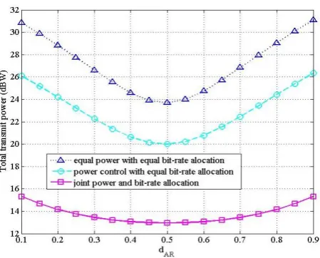
coefficient is set to 4 to model radio propagation in urban areas [10]. The number of sub-carriers T and the end-to-end rate requirement of the two sources are set to 16 and 10bit/s/Hz, respectively.
In Figure 2, we plot the total transmit-power as a function of dAR, where “equal power with equal
Figure 2. Total Transmit-power versus dar of the three compared schemes.
allocation” means that optimal power allocation of the three noes is used, and the end-to-end rate is equally allocated to all the sub-carriers. Of note is that the two compared schemes use all the T sub-carriers. It can be observed that the proposed joint power and bit-rate allocation algorithm can significantly reduce the system transmit-power in contrast to the schemes of “equal power with equal bit-rate allocation” and “power control with equal bit-rate allocation”. It is worth-mentioning that for the proposed joint power and bit-rate allocation algorithm, not all the T sub-carriers are used, and only the sub-carriers with high channel quality are adopted to deliver messages.
Conclusions
In the paper, an energy-efficient problem of a multi-carrier wireless bidirectional relaying system was investigated, where two source nodes communicate with each other via an amplify-and-forward relay, and the three individual nodes’ transmit-powers and the end-to-end rate requirements of the two sources are jointly optimized. As a result, a joint power and bit-rate allocation algorithm was proposed so as to minimize the system transmit-power. Our simulation results validated the derived expressions and confirmed the efficiency of the proposed algorithm. It is shown that with the proposed algorithm, the total transmit-power is significantly reduced compared with the conventional schemes with equal power and bit-rate allocation, and with power control only.
Acknowledgment
This work is supported in party by the National Natural Science Foundation of China (Grant Nos. 61401238 and 61871241), and by the Nantong University-Nantong Joint Research Center for Intelligent Information Technology (Grant No. KFKT2017A03).
References
[1] X. Ji, W-P. Zhu, and D. Massicotte, “Transmit power allocation for asymmetric bi-directional relay networks using channel statistics,” IET Commun, vol. 9, no. 13, pp. 1649-1660, Sept. 2015. [2] X. Ji, W.-P. Zhu, D. Massicotte, and M. Ahmed-Ouameur, "Energy efficient power allocation and relay location for asymmetric bi-directional relaying," in Proc. of IEEE GlobalSIP2015, UAS, Orlando, 2015, pp. 1225-1229.
[3] C. Sun, Y. Cen, and C. Yang, “Energy efficient OFDM relay systems,” IEEE Trans. Commun., vol. 61, no. 5, pp. 1797-1809, May 2013.
[5] C. Zhang, J. Ge, J. Li, F. Gong, Y. Ji and M. A. Farah, “Energy efficiency and spectral efficiency tradeoff for asymmetric two-way AF relaying with statistical CSI,” IEEE Trans. Veh. Technol., vol. 65, no. 4, pp. 2833-2839, April 2016.
[6] Q. Cui, T. Yuan and W. Ni, “Energy-efficient two-way relaying under non-ideal power amplifiers,” IEEE Trans. Veh. Techno, vol. 66, no. 2, pp. 1257-1270, Feb. 2017.
[7] Z. Sheng, H. D. Tuan, T. Q. Duong and H. V. Poor, “Joint power allocation and beamforming for energy-efficient two-way multi-relay communications,” IEEE Trans. Wirel. Commun, vol. 16, no. 10, pp. 6660-6671, Oct. 2017.
[8] X. Ji, Z. Bao, C. Xu, and J.-F. Gu, “Power adaptation for energy efficient bi-directional relaying with quality-of-service requirement and individual peak-power limit,” Wire. Personal Commun, vol. 95, no. 3, pp. 2413-2435, Aug. 2017.
[9] X. Ji, W.-P. Zhu, and D. Massicotte, “Transmit power minimization for two-way amplify-and-forward relaying with asymmetric traffic requirements,” IEEE Trans. on Veh. Technol., vol. 65, no. 12, pp. 9687-9702, 2016.