International Doctorate School in Information and Communication Technologies
DISI - University of Trento
Power Management and Power Consumption
Optimization Techniques in Wireless Sensor
Networks
Andrey Somov
Advisor:
Prof. Roberto Passerone
Universit`a degli Studi di Trento
Abstract
ing, WSN Synchronization, Gas Sensor, Wireless Brain-Machine]
This is a great opportunity to express my gratitude and respect to all the people who
supported me while I was doing my PhD. They all contributed to this work each in his/her
own way.
It is difficult to overstate my gratitude to my PhD supervisor Prof. Roberto Passerone.
First, I would like to thank him for guiding and inspiring me during my research period
at the University of Trento and for showing me what research is about. Secondly, I highly
appreciate his support not only in my research work but also in different life situations
where he was assisting me in any possible way. Finally, I should thank him for provided
encouragement throughout my thesis-writing period and the final prove ready of this
work. I would have been lost without him.
I would like to express my gratitude to Prof. Alexander Baranov (Moscow Aviation
Technological University) who encouraged me to enter the University of Trento and
in-vigorated me throughout the entire period of research.
I would like to thank Prof. Jan Rabaey, for giving me a great opportunity to work
during four months in his research group at UC Berkeley. A special thank I need to
give to one of the members of his group Michael Mark, who, since my arrival, became
my research companion. We performed a lot of research work together and continue our
collaboration. I am also pleased to thank other researchers I met at the UC Berkeley and
in particular Christine Ho, Louis Alarcon, and David Chen.
I would like to thank all the administrative and technical staff of the University of
Trento, and in particular Galina Kamburova, Manuel Zucchellini, Alessandro Tomasi,
and Sebastiano Perisi.
I am indebted to my many student colleagues from University of Trento for providing
a stimulating and fun environment in which all of us learn and grow. I am especially
grateful to Anton Ageev, Andrei Papliatseyeu, Ivan Minakov, Olga Zlydareva, Nadzeya
always ready to help and support me. I would also acknowledge my friends from an
enor-mous Russian-spoken community at our university, and in particular I am very thankful
to Marina Repich, Ruslan Asaula, Alena Simalatsar, Ivan Tankoyeu, and Denis Babenko.
Lastly, and most significantly, I wish to thank my parents Nina Somova and Sergey
Somov and my girlfriend Julia. They helped me, believed in me, supported me, and loved
me. To them I dedicate this thesis.
1 Introduction 1
1.1 The Context . . . 1
1.2 The Problem . . . 3
1.3 The Solution . . . 4
1.4 Innovative Aspects . . . 5
2 State of the Art 8 2.1 System-Level Design Methodologies . . . 8
2.1.1 Platform-Based Design . . . 9
2.1.2 Rialto Framework . . . 9
2.1.3 COSI Framework . . . 10
2.2 SystemC: System-level Design Language . . . 10
2.3 Network Simulators . . . 11
2.3.1 NS-2 simulator . . . 11
2.3.2 OMNet++ simulator . . . 11
2.3.3 TOSSIM . . . 12
2.3.4 VIPTOS and VisualSense . . . 12
2.3.5 AVRORA . . . 13
2.4 Battery Models . . . 13
2.5 Energy Harvesting . . . 14
2.6 Energy Storage Devices . . . 16
2.6.1 Basic Battery Theory . . . 17
2.6.2 Rechargeable Nickel Metal Hydride Batteries . . . 19
2.6.3 Rechargeable Lithium-based Batteries . . . 19
2.6.4 Solid-state Thin Film Batteries . . . 20
2.6.5 Supercapacitors . . . 21
2.6.6 Solid-state Electrochemical Capacitors . . . 21
2.7 Energy Efficiency and Power Management . . . 23
2.8 Energy Scavenging Platforms for WSN . . . 24
2.8.1 Everlast and ZebraNet Platforms . . . 24
2.8.2 Heliomote, Prometheus, and Trio Platforms . . . 26
2.8.3 VIBES, PMG Perpetuum, and PicoCube Platforms . . . 27
2.8.4 Electroacoustic Liner System . . . 28
2.8.5 AmbiMax Platform and Platform by Cymbet . . . 28
2.9 Power Saving Techniques . . . 29
2.9.1 Adaptive Power Management in Energy Harvesting Systems . . . . 29
2.9.2 Adaptive Duty Cycling for Energy Harvesting Systems . . . 29
2.9.3 Energy Management Architecture for Wireless Sensor Networks . . 29
2.9.4 High-level Model for Estimating Power Consumption of Bluetooth Devices . . . 31
2.10 Synchronization in WSN . . . 31
2.10.1 Approaches to WSN synchronization . . . 31
2.10.2 Synchronization Uncertainty Sources . . . 32
2.10.3 The Time-Stamp Synchronization protocol . . . 33
2.10.4 The Reference-Broadcast Synchronization protocol . . . 33
2.10.5 The Timing-sync Protocol for Sensor Networks . . . 33
2.10.6 The Flooding Time Synchronization Protocol . . . 34
3 A Methodology for Power Consumption Evaluation in Wireless Sensor Networks 35 3.1 Methodology . . . 36
3.2 Case Study . . . 39
3.2.3 The Energy Source . . . 42
3.3 Spice Compatible NiMH Battery Model . . . 43
3.4 Battery Model Verification . . . 45
3.5 Experimental Resullts . . . 48
4 An Energy Scavenging Module 51 4.1 System Concept . . . 51
4.1.1 The Energy Scavenging Module Architecture . . . 52
4.1.2 The Algorithm for Efficient Power Supply Switching . . . 53
4.2 Implementation . . . 54
4.3 EnTick Evaluation . . . 55
4.3.1 Experimental Setup . . . 55
4.3.2 Results and Analysis . . . 56
4.3.3 Potential Application . . . 58
4.4 TreBer module . . . 61
4.4.1 Printed Capacitors . . . 61
4.4.2 Printed Capacitor Prototype . . . 63
5 An Optimal Synchronization in Wireless Sensor Networks 65 5.1 Problem Formulation and Model Description . . . 66
5.2 Simulation Results . . . 71
5.3 Experimental Results . . . 72
6 Combustible Gases and Early Fire Detection 76 6.1 Background and Motivation . . . 77
6.2 System Overview and Principles of Operation . . . 78
6.3 Gas Sensor Module Implementation . . . 80
6.4 Experimental Results . . . 81
6.4.1 Pre-fire Detector Response . . . 81
6.4.2 Gases Detection . . . 82
6.4.3 Sensitivity Investigation . . . 82
6.4.4 Energy Consumption . . . 83
6.4.5 ESM as a Power Supply . . . 85
6.4.6 System Deployment . . . 86
7 Powering of Wireless Brain-Machine Interfaces 95 7.1 Powering via RF . . . 96
7.2 E-Class Amplifier . . . 98
7.2.1 E-Class Amplifier Design . . . 98
7.3 Inductive Power Link . . . 101
7.4 Receive Circuit vs Receive Circuit Transformed into Resistor . . . 102
7.5 Voltage Feedback . . . 102
7.6 Final Results . . . 103
8 Conclusion 107 8.1 Summary . . . 107
8.2 Future Work . . . 108
Bibliography 110
2.1 Ambient power sources [98]. . . 15
2.2 Energy Storage Devices . . . 18
2.3 Energy Scavenging Platforms . . . 25
3.1 Energy conditions of the Telosb mote . . . 42
3.2 Battery model validation results . . . 47
3.3 Battery run time (simulation results) . . . 50
6.1 Gas sensor module energy consumption during the sensor heating up to 450 ◦C. . . 84
6.2 Gas sensor module energy consumption during the sensor heating up to 550 ◦C. . . 85
7.1 The efficiency dependance on C2 (Figure 7.7). . . 105
7.2 The efficiency dependance on L1 (Figure 7.7). . . 105
List of Figures
1.1 Typical WSN architecture and networking. . . 2
1.2 Sensor node anatomy. . . 2
1.3 Modular uniform technology. . . 6
2.1 Schematic of direct write, pneumatic dispenser printer [courtesy of C. Ho, UC Berkeley]. . . 22
2.2 The Energy Management Architecture [69]. . . 30
3.1 Methodology. . . 37
3.2 Input pulses used to discharge the battery. . . 40
3.3 Example of a zoomed pulse. . . 41
3.4 Controllable resistor. . . 43
3.5 Controllable capacitor. . . 44
3.6 Spice model of a NiMH battery. . . 45
3.7 Battery discharging with continuous 23 mA current. . . 46
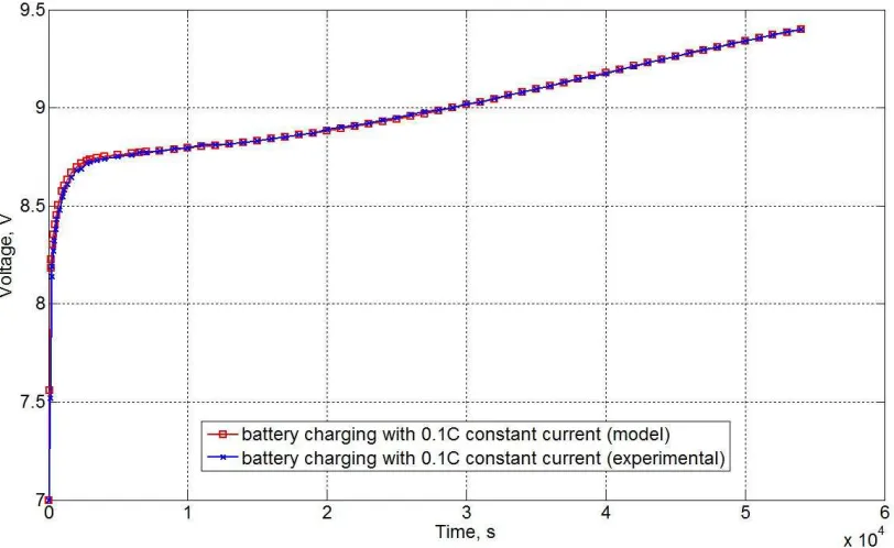
3.8 Continuous battery charging (0.1C). . . 47
3.9 Pulse battery discharging (0.1C). . . 48
3.10 Pulse battery discharging (0.2C). . . 49
3.11 100% duty cycle. . . 50
4.1 Architecture of energy scavenging module. . . 52
4.2 FSM explaining the choice of power supply for a sensor node. . . 53
4.3 The energy scavenging module - EnTick platform. . . 54
4.5 The charging and discharging of super capacitors. . . 57
4.6 The charging of Li-ion battery with solar panel. . . 58
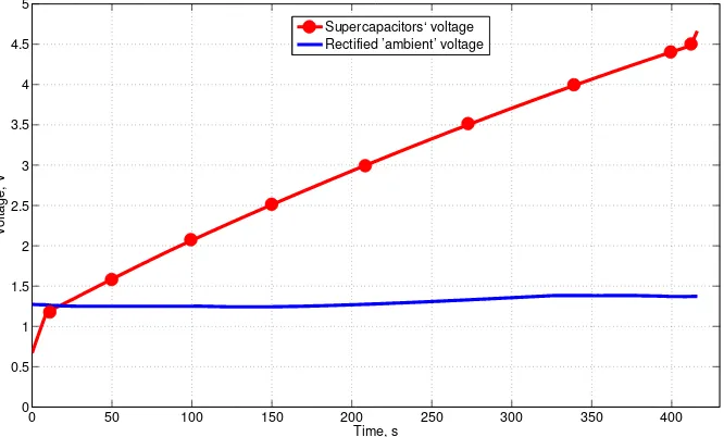
4.7 The charging of super capacitors with AC source. . . 59
4.8 Sketched paintball principles of our system. . . 60
4.9 Schematic of a carbon electrochemical capacitor [courtesy of C. Ho, UC Berkeley]. . . 62
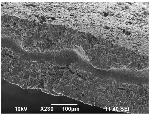
4.10 Micrograph showing the morphology of the carbon electrode and electrolyte active layers [courtesy of C. Ho, UC Berkeley]. . . 62
4.11 The prototype of printed capacitor. . . 63
4.12 Printed capacitor charge and self-discharge. . . 64
5.1 Qualitative power consumption patterns during the execution of monitoring and synchronization tasks on various nodes of a WSN. . . 66
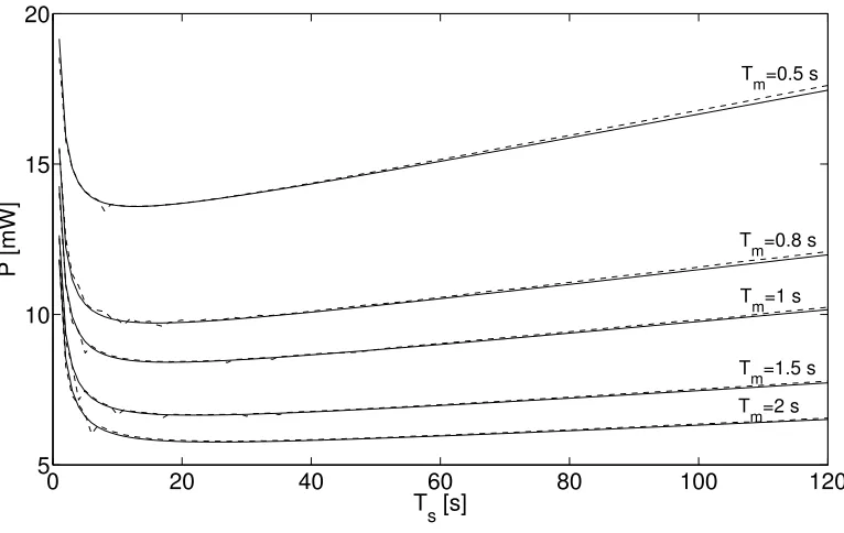
5.2 Average dissipated power as a function of the synchronization interval Ts for different periods of the monitoring task (i.e., Tm= 0.5,0.8,1,1.5,2 s). The solid lines result from (5.1), whereas dashed lines are obtained through simulations. In all cases the value of the worst–case frequency offset is νmax= 100 ppm. . . 70
5.3 Average dissipated power as a function of the synchronization interval Ts for different worst–case relative frequency offsets (i.e., νmax= 40,80,60,100 ppm). The solid lines result from ( 5.1), whereas the dashed lines are obtained through simulations. In all cases the period of the monitoring task is Tm = 0.5 s. . . 71
5.4 Experimental setup. Five Xbow TelosB nodes are programmed to run
both a periodic humidity monitoring task and the synchronization protocol
described in [25]. The applied voltage and current drain of a generic node
are measured simultaneously by means of two DMMs Agilent 34411A which
are connected to a PC collecting both measurement results and sensor
information by means of a further node (i.e. a sniffer). . . 73
5.5 Average power consumption as a function of the synchronization interval Ts for νmax = 22 ppm (namely the estimated maximum relative frequency skew in the considered WSN). In the picture, the solid line refers to the mea-surement values collected using the setup shown in Figure 5.4, the dashed line results from (5.1), and the bubble points correspond to simulations. The optimal synchronization period is T∗ s = 29.5 s. . . 74
6.1 Architecture of autonomous gas detection system. . . 79
6.2 Gas sensor module. . . 80
6.3 (a) 50% PWM generated by microcontroller, (b) variation in the sensitive layer’s resistance of the bulk-substrate sensor in relative units (upper graph) and PWM generated by microcontroller (lower graph), (c) variation in the sensitive layer’s resistance (in relative units) of the sensor made using the aluminum-oxide membrane (upper graph) and PWM generated by micro-controller (lower graph), and (d) variation in current running through the sensor’s (the sensor made using the aluminum-oxide membrane) heating element. . . 88
6.4 Sensor’s response to various gases at 500 ◦C: 1 the air; 2 pyrolysis; 3 -0.2% methane; 4 - alcohol fume. . . 89
6.5 Temperature of sensitive layer against various PWM modes under normal conditions. . . 90
6.6 Sensor response against various PWM heating modes. . . 90
6.7 Sensitivity of the sensor. . . 91
6.8 The charging and discharging of super capacitors. . . 91
6.11 Interface for network control. . . 93
6.12 Voltage level on solar panel, super capacitors, and Li-ion battery during 12-hour period. . . 94
7.1 How a fully-implantable BMI could restore limb mobility in paralyzed sub-jects or amputees [75]. . . 96
7.2 A generic wireless neural implant. . . 97
7.3 E-Class amplifier. . . 98
7.4 Desirable transistor waveforms of voltage and current in e-class ampli-fier [103]. . . 99
7.5 Class-E amplifier voltage [70]. . . 100
7.6 Inductive power link. . . 101
7.7 The final circuit in Cadence environment. . . 101
7.8 Inductive power link without the voltage feedback. . . 102
7.9 Capacitive voltage divider. . . 103
7.10 The efficiency dependance onC2 (Figure 7.7). . . 106
7.11 The Class-E voltage waveform. . . 106
Chapter 1
Introduction
This section introduces the problem and provides its positioning in the framework of the
main research areas of ICT (telecommunications, computer science, electronics).
1.1
The Context
From the very beginning, Wireless Sensor Networks (WSN) have been applied to
vari-ous difficult-to-access areas: environment and industrial monitoring, emergency services
and tracking of movements. WSNs provide the opportunity to build autonomous
sys-tems without the need to wire up an entire network, thus progressively replacing wired
embedded systems.
A WSN consists of wireless nodes which measure physical conditions using sensors
(i.e., temperature, humidity, vibration, pressure), digitize it and keep or distribute the
measured data over the network. The typical WSN architecture and data distribution is
depicted in Figure 1.1.
According to the application requirements, the wireless sensor nodes can be deployed
over a large area or can be amassed in a small section for the specific data measurements.
Applying a multi hop paradigm [27] the sensor nodes communicate the data to one or more
gates. The gate is a device which serves as a data sink and manages the “usual” nodes. In
fact, either one or more sensor nodes are able to operate as the gates, or another wireless
Figure 1.1: Typical WSN architecture and networking.
communications network, e.g., Internet. However, the feed back “user-sensor node” allows
the user to monitor the network, and do appropriate configuration and management, if
necessary.
A WSN contains a number of sensor nodes connected by a radio channel. A typical
sensor node block diagram is presented in Figure 1.2. It has four main blocks on a board:
a Central Processing Unit (CPU), memory (e.g., program memory, flash memory, volatile
memory), input-output (I/O) ports and a radio. Depending on the application, the sensor
node may have various extra hardware components on board.
Figure 1.2: Sensor node anatomy.
The sensor nodes have to meet several important requirements:
1.2. THE PROBLEM
operate using power efficient hardware and software technologies to increase its
life-time. Energy scavenging technology can improve the WSN lifetime and decrease the
cost of the network maintenance: the nodes are usually powered by AA cells, but
the batteries must be replaced when exhausted. According to OnWorld Research
the battery replacement cost will be $1 Billion in 2013 [44]. Energy scavenging
techniques are aimed at decreasing or even canceling the network maintenance cost;
Small form factor: to make it possible to embed the WSN into the daily environment, a high level of component integration of sensor node is required;
Low cost implementation: to increase the network reliability and accuracy of mea-sured data the density of the network must be high, therefore the cost per node
must be minimal.
Along with the listed advantages there is a serious limitation which will be described
below.
1.2
The Problem
Nowadays, WSNs are adopted in various applications: environmental and industrial
mon-itoring, vehicle detection, agriculture, entertainment and in military application.
How-ever, the challenges associated with the efficient power management and lifetime of WSN
nodes significantly constrain their functionality and potential applications. Moreover, the
energy constraints lead to the cost increase of WSN maintenance, especially for the
net-works deployed in remote areas. Thus, the problem of WSN long-term operation is of
vital importance.
The lifetime problem is a complex problem of WSN and can not be resolved one-sidedly.
It has to be addressed at three main levels:
Design - application, modeling, simulation;
Software - communication protocol, middleware, energy saving techniques.
At the design level the entire network operation and configuration depends on the
ap-plication. This application may determine the hardware architecture and power
manage-ment strategy of the sensor node and network. Besides, prior to hardware implemanage-mentation
of the node it should be modeled and the entire network has to be simulated.
The lifetime problem at the hardware level includes the correct HW components choice
along with energy efficient conversion and storage. Energy scavenging technology may
considerably increase the WSN lifetime, but for the maximum efficiency it is desirable to
apply it with the maximum power point tracking (MPPT) technique [89]. MPPT refers
to drawing power from an energy harvesting source at a level that maximizes the power
output. In fact, the MPPT can be either hardware or software.
Software plays an important role in WSN lifetime as well. For example, the adaptive
duty-cycling algorithm [66] allows the utilization of up to 58% more environmental
re-sources in comparison to the systems without this technique. Due to the fact that the
radio is the most power “hungry” component on board, the energy efficient middleware
and energy efficient techniques are required.
1.3
The Solution
To overcome the lifetime problem of WSN we address it at three main levels: the design
level, the hardware and the software, as defined previously in Section 1.2.
At the design level we propose a methodology for power consumption evaluation. This
methodology is a flexible and extensible simulation framework for power consumption
estimation of sensor network applications for arbitrary HW platforms. This framework
allows designers of sensor networks to estimate power consumption of the explored HW
platform which permits the selection of an optimal HW solution and SW implementation
for the specific projects.
The designed EnTick platform is aimed to resolve the WSN lifetime problem from
the HW point of view. This platform supports an energy scavenging technology which
1.4. INNOVATIVE ASPECTS
energy buffer based on off-the-shelf components such as rechargeable batteries and super
capacitors, so that the sensor node can be supplied either from super capacitors or the
battery or directly from the ambient source. The energy is delivered to the sensor node
in accordance to an efficient energy supply switching algorithm. In addition, we have
developed a modification of the EnTick platform called “TreBer”. The TreBer platform
is identical to the EnTick architecture and uses the same HW components, but instead
of off-the-shelf super capacitors we use an electrochemical supercapacitor (with improved
electrical characteristics) printed directly on the bottom of the module using the
“di-rect write” technology [29]. The smaller size of this platforms increases the potential
applications of WSN, and support the harvesting components of different kinds.
Since the radio module is usually the most energy-consuming component in tiny,
low-cost sensor devices, node long-term operation can be extended by duty cycle reduction of
the radio chip. The second way of energy saving on the radio is simply to turn it on to run
the task of assigned application, whereas it could be in sleep mode at the remaining time.
In fact, this approach is effective in case when the tasks are scheduled periodically and if
the nodes are synchronized well, i.e., have a common clock. In reality, if the network is
unsynchronized, some of the nodes may wake up while others are sleeping, so that some
connections can not be established. Due to the fact that time synchronization among
the nodes can be maintained within the bounds of known uncertainty solely by
recur-rently adjusting the local clocks, synchronization tasks can also be scheduled periodically.
According to this, we devised an analytical criterion which determines the value of the
synchronization period to minimize the average power consumed by a sensor node. The
proposed approach is validated by both simulations and experiments.
1.4
Innovative Aspects
At the design part of the thesis we present a methodology for power consumption
es-timation of a sensor node. Except for the traditional three layers of abstraction, i.e.,
event-driven simulation engine and HW model composer, and allows a user to describe the
ap-plication using a set of service calls and user functions described in the C/C++ language.
Another contribution of the framework is that the evaluation procedure is automatic.
Be-sides that, we have strengthened current tools for power consumption analysis by adding
the energy source layer which enables a power management of the entire system on the basis of battery model. Therefore, the developed methodology provides a user with a
flexible and detailed analysis of power consumption of the sensor node.
The core idea of the HW part is to apply a modular uniform technology for WSN
(see Figure 1.3) with a power management technique. The entire system contains three
main parts: a harvesting component - the energy scavenging module (the EnTick) - the
wireless sensor node. Of course, we have in mind that ambient power source is the main
power source for the all the blocks in the system. A harvesting component, for instance
a solar panel or a piezoelectric converter, converts ambient energy into electric energy.
As a matter of fact, the EnTick platform is a mediator between a harvesting component
and the sensor node: any sensor node can be connected to any harvesting component
via the mediator which enables the harvesting of both (AC) and (DC) based ambient
energy. Besides, the mediator enables to keep the collected energy in twolevel storage
-rechargeable battery and two super capacitors wired in series.
The TreBer platform has the printed capacitors on board manufactured using the
“direct write” technology.
Figure 1.3: Modular uniform technology.
Afterwards, we investigated how synchronization of WSN affects the power
consump-tion. An optimal synchronization technique conduces to lifetime increase of the network.
This approach proves that the average power consumption of a generic WSN node can be
minimized without undermining communication reliability if the interval between
1.4. INNOVATIVE ASPECTS
has been validated by means of both simulations and experimental results and opens new
perspectives in the design of long-term monitoring applications for WSNs. The devised
formula for optimal period of synchronization will support the long-term operation of the
State of the Art
This chapter presents the state of the art pertaining to the research work presented in this
doctorate thesis. It includes the most relevant materials that form the background of the
presented research activity as well as a selection of the significant works performed by other
research groups in the world. The first four sections are dedicated to power management
at the design level. They introduce the system-level design methodology, system-level
design language, simulation frameworks, and overview of battery models. After that we
talk about energy harvesting technologies, energy storage devices, and discuss how to
scavenge, convert, and store ambient enery efficiently. Next we provide a description and
critical discussion of academic as well as industrial wireless sensor platforms with energy
harvesting technology application. Finaly, we overview recent software power management
techniques and describe the synchronization uncertainty together with synchronization
protocols used in WSN.
2.1
System-Level Design Methodologies
In this section we are going to present several System-Level Design (SLD) methodologies
2.1. SYSTEM-LEVEL DESIGN METHODOLOGIES
2.1.1 Platform-Based Design
Platform-Based Design (PBD) is a methodology that combines the specification,
valida-tion and synthesis steps of the design flow, while maintaining a clear separavalida-tion between
the corresponding models [35, 100]. By doing so, the designer can operate separately on
the distinctive steps and maintain a global view of the impact of his/her design decisions
on the final implementation. The methodology includes hardware and embedded software
design, where the design of the system starts at a high level of abstraction (initial
de-sign description) and proceeds to a detailed implementation by mapping the executable
functional model onto progressively more detailed architectures under a set of constraints.
2.1.2 Rialto Framework
There exist several SLD methodologies applying PBD principles developed in the area of
WSN design space exploration. Bonivento et al. have presented a new methodology for
the design of WSN [30], which is well correlated with the nature of our research work.
They introduced a framework called Rialto that initially included two basic platforms, the
application interface called Sensor Network Service Platform (SNSP) and the hardware
platform layer called Sensor Network Implementation Platform (SNIP). Lately this
frame-work was extended by a third intermediate layer called Sensor Netframe-work Adhoc Protocol
Platform (SNAPP) that defines a library of communication protocols and the interfaces
that these protocols offer to the SNSP. This framework allows the application description
independently from the network architecture. The sensor network service platform is used
to describe an application in a Rialto Model in terms of logical component queries and
commands. This model is then translated into RialtoNet format that allows exploration
of the possible sequence of queries and commands from the application. Later the
func-tional description is mapped into an architecture platform instance. This work is focused
mainly on high level operating system services, while we will focus on single node platform
2.1.3 COSI Framework
The COmmunication Synthesis Infrastructure (COSY) [91] developed by Alessandro Pinto
et al. is a framework for the design exploration and synthesis of interconnection networks,
where “interconnection networks” refers to networks on-chip (NoC) as well as distributed
embedded systems. They introduce a general methodology for the design space
explo-ration of networks that allows studying of the optimization algorithms, communication
protocols, partial designs, and models for interconnection design in terms of network
per-formance and cost. We can apply this methodology in the future while extending our
methodology for being used for a whole WSN power consumption estimation.
2.2
SystemC: System-level Design Language
SystemC is a language created by the Language Open Group (LOG) of the Open SystemC
Initiative (OSCI), and is targeted to a wide range of designers. SystemC supports different
models of computation and allows the design of heterogeneous systems [108], [59].
Basi-cally, SystemC is a C++ class library, where C++ plays the role of language foundation
while the library provides both a notion of process and interface, and a simulation
ker-nel based on the Discrete-Event model. The SystemC library includes its own structural
elements like modules, ports, interfaces and channels (signals, FIFO, mutex, semaphores
etc.). It also introduces new data types, such as 4-valued logic, bits and bit vectors,
arbitrary precision integers and fixed-point types, which are useful in the specification of
hardware components. Additional libraries, like the Verification Library and the
Hetero-geneous System Specification Methodology Library (HetSC), have also been developed to
extend the original functionality of the language. SystemC suits very well for building
executable hardware and software models, but it does not support mapping of functional
2.3. NETWORK SIMULATORS
2.3
Network Simulators
This section reviews the most popular network simulators in the WSN research
commu-nity.
2.3.1 NS-2 simulator
NS-2 [11], perhaps, is the most popular general purpose network simulator. NS-2
sup-ports simulation for widely used IP network protocols. These include TCP, routing and
multicasting protocols for conventional wired and wireless networks. NS-2 has a highly
ex-tensible object-oriented architecture with discrete-event engine. Its object-oriented model
allows extension of simulation functionality by adding customers components and libraries.
The simulation in NS-2 environment is based on a combination of C++ and OTcl [14]
languages where protocols are implemented in C++. OTcl is used as a scripting language
to describe and control the simulation process. The complexity of NS-2 object-oriented
model creates substantial dependencies and execution overheads. It makes impossible
to scale simulation for a large number of network units, which is inherent to WSNs.
While object-oriented model is advantageous in terms of extensibility, it is a restriction
for scalability and performance. Besides, NS-2 does not provide representation for the
HW network components.
2.3.2 OMNet++ simulator
Like NS-2, OMNet++ [13] provides deep analysis of network activities at the packet layer.
Besides, OMNet++ provides a GUI front-end for simulation and debugging processes. It
has a component-based architecture with a discrete-event simulation kernel. It exploits
modules and channels to implement and connect simulation components, where
compo-nents are connected in a hierarchical fashion via generic interfaces (gates). OMNet++ has
extension for sensor network simulation, called SenSim [67]. It represents sensor node as
modular hierarchical structure of simple OMNet++ components. This simulatorprovides
more scalability and runs faster than NS-2. However, despite the apparent benefits of
in turn, does not allow to study sensor networks from an energy perspective.
2.3.3 TOSSIM
TOSSIM simulation environment is included in the TinyOS [21] framework. TinyOS has
gained general acceptance as a standard operating system for WSN applications. It has
a component-oriented programming model, based on the nesC language [9]. A TinyOS
program is presented as set of components, where each componnet is an independent
computational entity. The TinyOS framework includes a simple FIFO task scheduler
and hardware independent drivers for abstract HW components. The inter-component
communications occur through command-event mechanism. By changing a small
num-ber of TinyOS components, TOSSIM simulates the behavior of the low-level hardware.
It includes models for CPUs, analog-to-digital converters (ADCs), clocks, timers, flash
memories and radio components. The network communication over the wireless channel
is abstracted as a directed graph, where vertexes and edges represent nodes and links
between them, respectively. TOSSIM simulation architecture provides high level of
scala-bility and execution speed for the networks with large number of sensor nodes. However,
the abstract HW model of TOSSIM does not capture low-level details of timings and
interrupts, which can be important for precise power analysis. In addition, simulation is
supported only for the single HW platform (Micaz [43]). Obviously, it largely restricts
the applying scope.
2.3.4 VIPTOS and VisualSense
VIPTOS (Visual Ptolemy and TinyOS) is a graphical development and simulation
envi-ronment for TinyOSbased WSN applications [40]. VIPTOS bridges together the
Visu-alSense [22] simulator and the TinyOS framework. VisuVisu-alSense is a Ptolemy II [17] based
graphical simulation environment designed for WSNs. It exploits the actor-oriented
com-putational model of Ptolemy II, a general modeling framework for heterogeneous
embed-ded systems. VisualSense defines actor-oriented models for sensor node subsystems and
2.4. BATTERY MODELS
However, VIPTOS does not provide accurate HW representation of sensor node.
Sub-stantially, it focuses more on algorithmic and application domains. Additionally, VIPTOS
has been integrated only with the first version of TinyOS, which is not currently supported.
2.3.5 AVRORA
AVRORA [109], like TOSSIM, is one of the widely used WSN simulation tool. It exploits
cycle accurate instruction-by-instruction manner to run code. AVRORA runs actual
applications without the need to specially adapt it for simulation. AVRORA represents
each HW component as corresponding object classes thus as classes of CPUs, Timers, flash
memories, ADCs and off-chip components such as sensors. The HW model of a single
sensor node is the combination of such objects in a hierarchical manner. The CPU object
contains the simulation engine with the event queue for the entire node. This architecture
allows node replication for network simulation, where each node is run as independent
computational entity. However, AVRORA supports solely AVR MCU [1] cores and does
not provide any extensions for others CPU architectures.
2.4
Battery Models
The battery model is an essential part of the energy consumption evaluation framework
to analyse power dissipated during a sensor node operation.
Several battery models have been designed recently. However, in most cases each type
of the model makes an emphasis on specific battery purpose and has various levels of
accuracy. Mathematical battery models [94, 97] apply empirical equations to address the
battery charge/discharge behavior, efficiency, or simulate the electrochemical or thermal
behavior of the battery. In fact, the mathematical models can not be adopted for circuit
simulation since its accuracy lies in the range of 5-20% and do not provide one with the
current-voltage characteristic.
Electrochemical models [105, 47] are complex and require much time for simulation
since they typically present the battery at low level. However, the electrical models [60, 31,
easy to handle, provide the electrical engineers with the current-voltage characteristics,
and, finally, their accuracy lies within 5%.
The electrical battery model presented in [39] takes into consideration all dynamic
characteristics of the battery. It consists of two parts: battery lifetime evaluation and
voltage-current characteristics emulation. Battery lifetime evaluation part contains a
resistor, which determines energy loss during long idle period, a capacity to characterize
battery charge, and a current, which is applied to charge or discharge the battery. The
voltage-current characteristics emulation part of the model contains open-circuit voltage,
which is able to change according to the state of charge (SOC) of the battery, and an RC
network. This model is both intuitive and capable to predict an accurate runtime and
voltage-current parameters.
2.5
Energy Harvesting
This section reviews conventional outdoor energy sources. The goal of this section is not
to suggest the best way of ambient energy conversion to power wireless sensor node, but
to understand their potential as an alternative power source.
Renewable environment sources have inherent advantages compared to nonrenewable
sources like oil, coal, gas, and nuclear. The merits are as follows: they are non-polluting,
and do not require maintenance.
As it is presented in Table 2.1 the most attractive way for energy harvesting is solar
light. For all technologies, the energy is available only under particular environmental
conditions: sunlight, vibration, high temperature, surrounding noise. Each given form
of energy can be harvested by a different class of generator that performs conversion to
electricity. That is why wireless sensor nodes have to keep energy in storage elements. In
this case, a reasonable solution seems to be the combination of an energy storage system
and scavenging technology. Various power sources were explored, but we will consider
only the most adequate ones for application in WSN domain.
The first three sources provide the higher power density and are therefore more
2.5. ENERGY HARVESTING
Harvesting technology Power density Solar cells (outdoor at noon) 15 mW/cm2
Piezoelectric (shoe inserts) 330 µW/cm3
Vibration (small microwave oven) 116 µW/cm3
Thermoelectric 10 ◦C gradient 40 µW/cm3
Acoustic noise (100 dB) 960 nW/cm3
Table 2.1: Ambient power sources [98].
wireless nodes with energy scavenging technology amid designers. Photovoltaic power
can be produced in many ways with widely varying efficiency and cost. Solar technology
can be divided into two main groups: discrete cell technology and integrated thin film
technology.
Discrete cell technology:
• Single-crystal silicon (15% efficiency of commercial modules);
• Multicrystalline silicon (14% efficiency of commercial modules);
• Edge-defined film-fed growth ribbons;
• Dendritic web;
• Gallium Arsenide (28% efficiency of research cell under concentrated sunlight).
Integrated thin film tehnology:
• Copper Indium Diselenide (17.7% efficiency of research cell);
• Amorphous Silicon;
• Cadmium Telluride (8.34% efficiency of commercial modules [19] ).
The technologies above are well described in the literature. However, photovoltaic
engineers developed advanced design for the discrete cell technology as concentrated
by means of three optical elements and increase conversion efficiency. But in this case,
conversion efficiency is reduced a bit because of overheating a cell during the radiation
concentrating process.
The core idea of innovative holographic technology, patented by Prism Solar
Technolo-gies [16], lies in using transparent holographic optical elements to collect, spectrally select
and focus useful wavelength of solar light onto the cell. The advantages of this technology
are: up to 85% economy of the silicon, transparent properties, low cost.
Vibration harvesting modality has less power density than solar. Three conversion
mechanisms are distinguished by which vibrations can be converted to electrical energy.
They are piezoelectric, electro-magnetic, and electrostatic. In piezoelectric conversion,
mechanical strain in a piezoelectric material produces a charge separation across the
material, generating a voltage. Regarding the electro-magnetic case, the relative motion
between a coil and a magnetic field produces a current to flow in the coil. Electrostatic
generation, in turn, contains two conductors separated by a dielectric, which move relative
to one another. As the conductors move, the energy stored in the capacitor changes, thus
providing the mechanism for mechanical to electrical energy conversion [98].
Wireless sensors platforms with energy harvesting devices are considered in Section 2.8.
2.6
Energy Storage Devices
Wireless sensor node with the energy scavenging technology application requires a buffer
to store harvested energy. This energy buffer allows the system to be supplied even if an
ambient source is unavailable at the moment. There are two popular energy storage
tech-nologies exploiting in WSN: rechargeable battery and supercapacitor. Both techtech-nologies
have advantages as well as disadantages. Thus, there are three typically used
combina-tions of these storage devices application: supercapacitor only, rechargeable battery only
or combination of them to supplement each other.
Of course, we mentioned the most popular storage devices. However, these devices can
be divided into sub groups. Besides, there are other power supply devices for sensor nodes,
2.6. ENERGY STORAGE DEVICES
applied in WSN.
Rechargeable battery (or a secondary energy buffer) is usually considered as a backup
energy source in WSN. It is being used when the supercapacitor (or a primary
en-ergy buffer is exhausted). It happens because of the limited number of the battery
charge/discharge cycles (300-500 cycles). However, rechargeable batteries have
signifi-cant energy density and low leakage current that provides the long-term energy storage
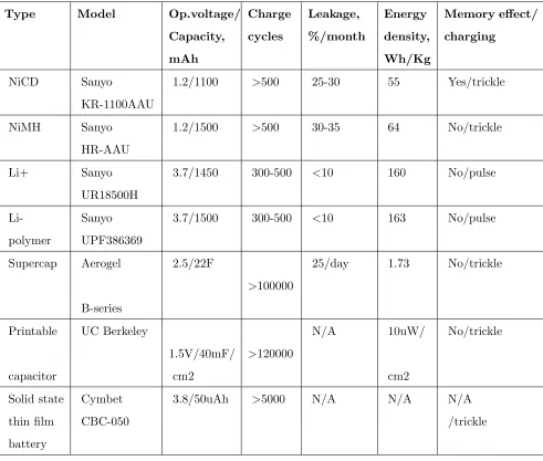
(see Table 2.2).
There are four main kinds of rechargeable batteries: NiCd, NiMH, Lithium-ion, and
Lithium-polymer. Lithium cells have the highest energy density, the lowest leakage current
per month, but require additional circuit for the charging. A single lithium cell provides
a system with high voltage. NiCd and NiMH rechargeable batteries have simple charging
circuit (or in individual case they do not require it at all).
2.6.1 Basic Battery Theory
A battery is made of two electrodes, a positive cathode and a negative anode, with a
porous separator between them. The time of battery charging is normally determined
by the milliamp hour (mAh) capacity of the battery. For a 400 mA source, for example,
charging a 400 mAh battery will take 400/400 = 1 hour (C), while charging a 200 mAh
battery will require 200/400 = 0.5 hours (0.5C). However, in reality, charging a battery
requires minimum 1.5*C to secure the complete replenishment [17]. In order to avoid
confusion, capacitance is designated as C (in italics) as distinct from battery capacity indicated with C.
Though progress in battery technology is not as rapid as in electronics and
comput-ing, with new battery chemistries and enhanced manufacturing techniques it has become
possible to create the smaller and more reliable batteries for handheld electronics. By the
present almost every small, portable electronic device is powered by rechargeable batteries
of the nickel metal hydride or lithium ion/polymer types. In the situations of a wall outlet
or a car adapter being easily accessible, the efficiency of battery charging is rarely taken
into consideration. It becomes crucial with the increase in demand for wireless sensors
Type Model Op.voltage/ Charge Leakage, Energy Memory effect/ Capacity,
mAh
cycles %/month density, Wh/Kg
charging
NiCD Sanyo 1.2/1100 >500 25-30 55 Yes/trickle KR-1100AAU
NiMH Sanyo 1.2/1500 >500 30-35 64 No/trickle HR-AAU
Li+ Sanyo 3.7/1450 300-500 <10 160 No/pulse UR18500H
Li- Sanyo 3.7/1500 300-500 <10 163 No/pulse polymer UPF386369
Supercap Aerogel 2.5/22F
>100000
25/day 1.73 No/trickle
B-series Printable UC Berkeley
1.5V/40mF/ >120000
N/A 10uW/ No/trickle
capacitor cm2 cm2
Solid state Cymbet 3.8/50uAh >5000 N/A N/A N/A
thin film CBC-050 /trickle
battery
2.6. ENERGY STORAGE DEVICES
devices (such as a capacitor) should be considered - these cases will be discussed later.
2.6.2 Rechargeable Nickel Metal Hydride Batteries
Nickel metal hydride (NiMH) batteries use hydrogen, absorbed in a metal alloy, as the
active negative material as opposed to cadmium used in nickel cadmium (NiCd) batteries
[79]. In rechargeable applications, NiMH batteries have, for the most part, replaced nickel
cadmium (NiCd) batteries. As compared to their NiCd relative, NiMH batteries are not
potentially harmful to environment, Furthermore, NiMH have no signs of the so-called
”memory effect” associated with the NiCd variety. The most widespread charging method
for NiMH batteries is a constant-current charge using limited current to avoid too great an
uprise of the battery temperature or not to exceed the rate of the oxygen-recombination
reaction [79].
Being easily accessible, nickel metal hydride batteries are known for their extremely
high discharge rate which makes their application for storing such relatively small amounts
of harvested energy rather questionable. In general, a nickel-based battery will discharge
10% to 15% of its capacity within first 24 hours after charging following which the
dis-charge rate makes additional 10% to 15% per month (cf. the li-ion self-disdis-charge of
approximately 5% for the first 24 hours and further 1% to 2% ) [46].
2.6.3 Rechargeable Lithium-based Batteries
The recent trend has been towards replacing nickel metal batteries with lithium ion
bat-teries characterized by even greater specific energy and energy density [79]. In
addi-tion, lithium ion cells have considerably higher discharge voltage (3.6 V), much lower
self-discharge rate as compared to NiCd and NiMH, and do not exhibit any memory
effects [87].
Rechargeable lithium ion batteries utilize a reversible insertion and extraction of
lithium ions into and from a lithium insertion compound during the discharging and
charging cycle [87].
The nominal open-circuit voltage of most widely used rechargeable lithium ion cells is
The capacity loss associated with the lithium’s side reactions inside the cell increases
with the depth of discharge per cycle. Some of the secondary lithium cells can reach many
cycles, though granted very shallow discharge conditions [71]. In other words, while the
majority of lithium based secondary batteries claim between 500 and 1000 charge cycles
of theoretical life, the actual life of the battery is typically much shorter than the upper
limit.
For safety reasons, the maximum charge and discharge current for a lithium ion
battery is limited to 1 C, though some up-to-date chemistries are able to ensure the
charge/discharge rate of up to 20 C. One of the core issues of lithium technology is the
fact that lithium metal starts melting at 180 ◦C. The liquid metal is highly reactive as
compared to solid state. Upon reaching its melting point, lithium tends to react with the
cathode material and the electrolyte’s components providing a considerable amount of
thermal energy [71]. For commercial and military aerospace applications this could mean
disaster or destruction during high altitude or outer space missions.
Unlike nickel metal hydride batteries, lithium ion charging requires additional circuitry
to prevent overcharging or overdischarging of the cell. Overcharging may be dangerous, as
described above, and both conditions can reduce the overall life of the battery. However,
despite the dangers associated with lithium ion batteries, they remain the portable option
of choice due to relatively high specific energy and energy density.
2.6.4 Solid-state Thin Film Batteries
CymbetT M Corporation manufactures the solid-state, rechargeable thin film batteries.
The batteries are packed into a tiny case that enables to use them directly on board of
a sensor node. In fact, the thin film battery technology used by Cymbet was originally
developed at Oak Ridge National Laboratory [12].
For many applications demanding high energy and power densities, good capacity
retention for thousands of discharge/charge cycles, and an extremely low self-discharge
rate, the ideal micropower sources are rechargeable thin-film solid-state lithium batteries.
They are able to secure high power levels, long cycle life, insignificant self-discharge and
2.6. ENERGY STORAGE DEVICES
vapor deposition processes [50]. Metallic lithium anode films are deposited by thermal
evaporation of the metal under vacuum. The lithium batteries’ capacity is limited by
the thickness of the cathode films, as the lithium film is several times thicker than that
required to cycle the battery.
The batteries fabricated using this technology can be adopted for a number of
applica-tions including backup power, implantable medical devices, redio-frequency transmitters.
2.6.5 Supercapacitors
Supercapacitors, also referred to as ultracapacitors or electrochemical double layer
capac-itors, differ from the conventional electrostatic and electrolytic capacitors as they contain
an electrolyte which enables the electrostatic charge to also be stored in the form of
ions [106]. Being governed by the same fundamental equations as conventional
capac-itors, they utilize the larger surface area electrodes and thinner dielectrics to achieve
greater capacitances [61]. Since these devices are designed to store energy using both
ionic capacitance and surface redox reactions, their classification is closer to the standard
battery’s one than to the classification of their conventional capacitor relatives.
It should be noted that, in literature, the two designations (super- and ultra-) are
often used interchangeably and are provided with vague definitions which only contribute
to the confusion rather than clarify it. Since both words are, in fact, applicable to the
same device, it has been proposed to designate such devices under the generic name
’electrochemical capacitor’ [106]. However, the term supercapacitor will still be used
hereinafter for convenience.
A model of a capacitor should comprise an Equivalent Series Resistance (ESR) to
account for internal losses. Depending on applications, the ESR may significantly affect
the voltage fluctuation across the capacitor during charging and the rate of current leakage
out of the capacitor over extended periods of inactivity.
2.6.6 Solid-state Electrochemical Capacitors
The utilization of organic solvents [42], and more recently novel ionic liquids [77] as
ranges than aqueous electrolytes that are only stable up to ∆1 V. As a result, energy
density, being a function of the square of the potential difference achievable in a
capaci-tor, increases significantly. Ionic liquids especially are interesting because they effectively
remain liquid at room temperature with negligible vapor pressure, and therefore are not
volatile [56]. Besides being safe and requiring less hermetic packaging, these novel liquids
provide an interesting opportunity when incorporated with polymer gels to form solid-like
films that maintain liquid-like properties. Developed a gel electrolyte with high
mechan-ical strength and good ionic conductivity by incorporating 1-butyl-3-methylimidazolium
tetrafluoroborate (BMIM+BF4-) ionic liquid with polyvinilydene fluoride (PVDF)
poly-mer [64]. Using this gel electrolyte, solid-state electrochemical capacitors can be deposited
utilizing direct write solutions processing.
Figure 2.1: Schematic of direct write, pneumatic dispenser printer [courtesy of C. Ho, UC Berkeley].
Direct write solutions processes are typically simple methods for depositing materials
additively onto a substrate at ambient and room temperature conditions. They provide
a suitable alternative to standard thin film microfabrication techniques for devices that
2.7. ENERGY EFFICIENCY AND POWER MANAGEMENT
have developed a pneumatic dispenser printing tool which extrudes slurries and solutions
onto a substrate mounted on a 3-axis stage with micron accuracy (Figure 2.1). Because
the deposition of solutions is gentle, films of different compositions can be deposited in
a subsequent manner, and devices can be built. Several direct write processes have been
used to deposit similar structures [63, 29], but the printer provides the added benefits
of reducing energy inputs and waste generated, as well as being able to deposit material
around existing components, effectively utilizing any open space on a substrate.
Ear-lier results have shown this method to be both cost effective and scalable for the mass
production [107].
2.7
Energy Efficiency and Power Management
It should be noted that efficiency may decrease due to the direct connection between
har-vesting components and energy storage devices. Efficiency break-down can be presented
as follows: efficiency of converting one form of energy to another, efficiency of transferring
from the source to the supply, efficiency of buffering after the energy has been harvested
and, finally, consumption efficiency.
The first thing to be considered with regard to energy harvesting is voltage.
Insuf-ficiently high voltage makes it difficult (if not impossible) to either directly power the
system or charge an energy storage device. Such systems as wireless sensor nodes are
built using analog and RF components that are sensitive to noise in the power supply.
What is needed, therefore, is voltage conversion to some known, controllable level to
secure consumption of regulated power.
The function of filling up the gap between the supply and the consumer is performed
by voltage regulators. Linear regulators have the advantage of providing the clean, stable
power required for analog/RF components. However, apart from the lower conversion
efficiency, they incur a voltage drop and dissipate more heat. Switching regulators
char-acterized by considerably higher efficiency and are widely applied for digital subsystems
which are more tolerant to noise.
harvesting source at the level maximizing the power output. For DC sources like, for
example, solar panels, the maximum power point (MPP) is a voltage-current
combina-tion which ensures the power output maximizacombina-tion under certain sunlight and
tempera-ture conditions. To achieve the power maximization, the supply and the load should be
matched in terms of impedance [101].
Finally, we would like to note that following the energy neutral mode [92], i.e. consume
only as much energy as harvested, will raise the opportunity of indefinitely long lifetime,
limited only by the hardware longevity.
2.8
Energy Scavenging Platforms for WSN
In this section we review recent wireless sensor platforms with the energy scavenging
technology application. Table 2.3 presents the overview of these platforms.
2.8.1 Everlast and ZebraNet Platforms
In this subsction we consider the sensor node platforms which are designed as a single
module.
Everlast [101] has only a primary energy buffer, because its designers consider
recharge-able batteries as lifetime limiting factor. Nevertheless, the system novelty concerns just
to super capacitors which could be efficiently charged using a Pulse Frequency Modulated
(PFM) converter and open-circuit solar voltage approach to track the maximum power
point. Lifetime of Everlast is predicted as 20 years operation requiring no maintenance.
ZebraNet [116] is a GPS based WSN for animal migration tracking with sensors built
in collars on neck of zebras. The wireless sensor node has the following HW features:
single energy buffer as lithium-ion battery, dual-clock microcontroller, separate power
supplies for each device to lower energy consumption, and off-chip memory since the
system has to generate detailed logs. The middleware of the system has GPS sensing and
radio communication as priority events, and the remaining events could be regarded as a
combination of scheduled and unplanned events. To reduce power consumption developers
2.8. ENERGY SCAVENGING PLATFORMS FOR WSN
Platform Goal or System Harvesting
Application Composition Technology
Everlast [101] Operating on supecaps, lifetime, low cost, high performance, durable WSN
Everlast node Solar radiation
Heliomote [93]
Simplicity, ecosystem sensing Mica2 [43] + heliomote board
Solar radiation
Prometheus [68]
Perpetual operation and prove of concepts
TelosB [43] + prometheus board
Solar radiation
Trio [52] Sustainable, flexible, scalable WSN, experementation purpose
TelosB [43] + XSM [51] + prometheus platform
Solar radiation
ZebraNet [116]
Efficient power management, miniaturization, zebra‘s movement tracking
ZebraNet node Solar radiation
VIBES [110] Lifetime, acceleration data measur-ing
VIBES node Vibration
PMG Per-petuum [15]
Battery-free sensor system, con-dition monitoring, industrial, aerospace
PMG sensor node Vibration
PicoCube [38] Small volume, tire presure monitor-ing
Five stacked boards Vibration
AmbiMax [89] Multiple harvesting components adoption
Eco node Wind, solar radia-tion, thermal, vi-bration
Electro acous-tic liner system [90]
The suppression of aircraft engine noise
Self-powered node Acoustic noise
Cymbet CBC-EVAL-08 [44]
Quick development of energy har-vesting applications, commercial sensor node
Cymbet CBC-EVAL-08 module
and dual clock scheme which assists to consume twice less energy using a slow clock.
Besides, the ZebraNet node has evolved through different versions, but none of versions
apply thought-out SW power management.
2.8.2 Heliomote, Prometheus, and Trio Platforms
In this subsection we rereview the sensor node platforms which contain several bords in
the module, e.g. are composite constructions.
Prometheus [68] is a wireless sensor platform which includes the Prometheus power
board and Telos. The entire system is being powered by the Prometheus power board.
This power board is implemented with a two-stage storage system containing two
super-capacitors as a primary buffer and a lithium rechargeable battery as a secondary buffer.
The two supercapacitors are wired in series to decrease leakage of current. The lithium
battery is charged only from the primary buffer where energy is stable and pulsing is
pos-sible. The SW of the Prometheus platform is pushed to the Telos MicroController Unit
(MCU). Developers reduced the number of components on a board and thus decreased
power consumption and board space having performed control logic by means of MCU.
Developers of this system claim 43 years operation under 1% load, 4 years under 10%
load, and 1 year under 100% load [68].
Prometheus, Telos [43] and XSM [51], in turn, are combined into the Trio [52] node.
Telos is necessary for low power operation, Prometheus is responsible for solar power
supply and whole charging system, and finally XSM is a set of indispensable sensors.
Prometheus in this case is modified in order to enhance its performance and guarantee
fail-safe operation. The system has a four-tier HW architecture: (1-st) mote tier performs
sensing, local processing and communication, (2-nd) gateway tier forward traffic between
server and mote tiers, (3-rd) server tier monitors and collects network statistics,
multi-plexes traffic from several gateways, and (4-th) client tier runs client applications. Each
tier has special SW: the mote tier is controlled by system SW, besides application SW
and middleware services manage mote, server, and client tiers.
Heliomote platform has solely NiMH rechargeable batteries as energy buffer. HW
2.8. ENERGY SCAVENGING PLATFORMS FOR WSN
and undercharge protection, and an on-board power monitor integrated circuit. Because
of the inherent leakage and due to the increased overhead of energy storage management,
developers renounced exploiting the super capacitors.
2.8.3 VIBES, PMG Perpetuum, and PicoCube Platforms
VIBES [110], PMG Perpetuum [15] and PicoCube [38] are microsystems powered from
ambient vibrations. The intended application for the VIBES sensor node is an air
com-pressor unit, though vibrations and frequencies measured pointed out an opportunity of
different industrial applications. The microsystem, in general, contains three main units:
the microgenerator, converting ambient vibration energy into electrical energy, the voltage
multiplier, which converts and stores the energy in a super capacitor, and the
microcon-troller based subsystem consisting of an accelerometer and RF transmitter. VIBES is
an energy aware system and has a possibility to adjust the duty cycle according to the
available energy.
The second platform based on vibration energy-harvesting microgenerator is PMG
by Perpetuum. PMG platforms by Perpetuum have three types of sensor nodes each
developed for a particular application, namely PMG-17 is intended for control of plant
machinery and continuous monitoring, PMG-27 enables aerospace industry, PMG-37 was
developed for transportation applications. PMG platforms have a primary energy buffer
for improved flexibility and do not require any maintenance. The PMG-17 energy
har-vester, for instance, can generate around 50 mW at 1g that enables to operate
contin-uously. The technical parameters of PMG platforms open up new potentialities for the
most data intensive applications. Depending on the application, the PGM node can
be configured to transmit large data bursts rarely or transmit smaller data burst more
frequently, for example, for data in a dynamic environment.
The PicoCube is a 1 cm3
sensor node which consists of five stacked printed boards:
radio, switch, sensor, MCU, and storage. However, the node does not contain a harvesting
device. The harvested energy is being stored in a NiMH battery. In the future, the authors
plan to exchange the packed battery with a battery manufactured by using direct write
2.8.4 Electroacoustic Liner System
Self-powered electroacoustic liner system [90] was designed specifically for the suppression
of aircraft engine noise. The module consists of three subsystems: energy harvesting,
com-munication, and impedance tuning. One of two electromechanical Helmholtz resonators
(EMHR) is assigned for energy harvesting whereas the second one for noise supression.
However, more EMHR can be used if more power is required to supply the system. The
designed module has a secondary energy buffer as a rechargeable battery.
2.8.5 AmbiMax Platform and Platform by Cymbet
Two wireless sensor node platforms reviewed in this section support more than one energy
harvester. However, their organization of energy buffers is various.
AmbiMax platform [89] enables the energy harvesting of solar, thermal, vibration, and
wind. AmbiMax is comprised of energy harvesting system, reservoir capacity array, and
control/charger. Each energy harvesting device collects ambient energy and replenishes its
own reservoir capacitors. These different reservoir capacitors make up the whole reservoir
capacity array. Furthermore, the platform has the secondary or in other words backup
energy buffer as a rechargeable battery which is being used when the supercapacitors
are discharged and there is a lack of ambient energy. To charge the supercapacitors
at maximum efficiency the maximum power point tracking mechanism is applied. This
method reveals the optimal power output at the given level of available ambient energy.
CBC-EVAL-08 node [44] is a demonstration kit designed by Cymbet Corporation.
This node has a small solar panel on board as well as it enables the AC-based ambient
signal harvesting. An external AC-based harvester can be connected to the node through
the connector on the board. To keep the harvested energy, the module has two 50 uAh
EnerChip batteries manufactured by application of the thin film technology [24]. In order
to save as much energy as possible, the module supports SimpliciTI [20] the energy aware
wireless network protocol. The power management block allows the preventing of deep
battery discharge and the monitoring of high current operation. In spite of low battery
2.9. POWER SAVING TECHNIQUES
lasting of the module operation.
2.9
Power Saving Techniques
The hardware solutions considered in the previous section can significantly increase a
wire-less sensor node lifetime. But non-intelligent hardware can not expand energy resources
efficiently without appropriate power management techniques. In this section we consider
the power saving techniques for WSN aimed to economical usage of energy resources and
efficient management of sensor node hardware.
2.9.1 Adaptive Power Management in Energy Harvesting Systems
The authors of [85] propose an adaptive power management approach with the goal of
decreasing the duty cycle when the scavenged energy is not enough for operating and vice
versa to increase the duty cycle at that time when the scavenged energy is sufficient.
The estimation task of the model proposed, based on previous measurements, predicts
the scavenged energy available in the future, and a controller adjusts properties of the
application. The feature of given approach is that energy is stored in a buffer before being
utilized.
2.9.2 Adaptive Duty Cycling for Energy Harvesting Systems
In contrast to [85], [66] allows both direct and stored usage of the energy from harvesting
source, but in both cases energy has to be measured. The proposed algorithm has three
main goals, namely (a) load should not consume more energy than it is provided by
the environment, (b) adjust to the dynamics of the energy source in the field (while [85]
proposes parameterized specification and the calculation by online controller), (c) improve
the system performance according to application utility model.
2.9.3 Energy Management Architecture for Wireless Sensor Networks
[85] and [66] are based on preliminary measurements and historical data to adapt the duty
(EMA) [69] for WSN, in general, is grounded upon prioritized enforcement of policy
theory at the time of operation. It means that EMA at first performs a prioritized task,
and so on in decreasing order.
Figure 2.2: The Energy Management Architecture [69].
EMA presented in [69] considers energy as a crucial component and contains three
basic components: a specification component, an energy monitor, an energy manager.
The goal of the specification component lies in providing a set of interfaces and
connect-ing the energy policy to the monitor and the manager. The monitorconnect-ing component, in
turn, supervises granular component energy usages according to a set of interfaces to the
application. Besides, it observes the overall system energy such as remainder battery
energy and incoming collected energy. The management component gets energy
infor-mation from the monitoring component in order to oblige user policies to be transferred
by the specification component and executes admission control on activities by means of
2.10. SYNCHRONIZATION IN WSN
2.9.4 High-level Model for Estimating Power Consumption of Bluetooth De-vices
The authors of [82] offer a novel technique to estimate the power consumption of Bluetooth
modules. The estimation technique is based on a measurementbased approach devised
to assure a suitable trade-off between estimation time, accuracy and number of prior
measurements. The trends in this area of research will lead to the opportunity of power
consumption estimation for each module of the embedded system. However, we can
predict power consumption from the battery point of view. The battery model in [39]
takes into consideration all dynamics characteristics of the battery with an opportunity to
predict lifetime. The decision of the power consumption estimation of Bluetooth modules
is valuable for circuit designers since it helps to extend battery runtime and minimize
power dissipation. We will use this technique to improve power management optimization.
2.10
Synchronization in WSN
Time synchronization is essential in WSNs to coordinate activities performed by
multi-ple nodes: multisensor data fusion, time-scheduling operations, and power-efficient duty
cycles. However, time synchronization in WSNs is a specific field differing from the
synchronization in wired networks [72, 96], since it requires the consumption of limited
resource - energy. Moreover, radio chip is the most power-hungry component of sensor
node [43]. Hence, it is a challenging task to effectively maintain WSN nodes synchronized
while minimizing power consumption.
In this section we describe several synchronization techniques which aim at
synchro-nizing the network while focusing to a variable extent on such competing characteristics
as accuracy, power efficiency, reliability, and simplicity.
2.10.1 Approaches to WSN synchronization
There are several features in which synchronization protocols differ from one to another
to provide best-fit solution for particular cases [96]. The synchronization is said to be
(e.g. UTC); or it is referred to as internal when only relative time differences between network nodes are compensated within given uncertainty boundaries (any node might
be used as time reference). For this purpose, a group of network nodes can use one
particular time value received from some sender (sender-receiver approach); conversely, those devices can register the arrival time of one radio message and then exchange these
timestamps between them to know the time of each other (receiver-receiver approach). Clock correction is used when each node adjusts its clock; clock transformation instead is used when every node stores differences between its own clock reading and the clock
readings of other network nodes to estimate their time. The synchronization can be
periodic (i.e. performed repeatedly after some period) or it can be on-demand when network nodes are synchronized peradically, e.g. after some particular event.
2.10.2 Synchronization Uncertainty Sources
In order to be synchronized, network nodes must exchange some information related to
time. The way in which that information i