Transformation and Composition of Software Design
Models for Model Driven Development
Dulani Meedeniya
1, Indika Perera
2 Department of Computer Science and EngineeringUniversity of Moratuwa Sri Lanka
1[email protected], 2[email protected]
Juliana Bowles
School of Computer ScienceUniversity of St Andrews United Kingdom [email protected]
Abstract— Software models play a significant role with the
growth of software system development based on Model Driven Development (MDD) approach. Model transformations and compositions are the heart of MDD and allow the development of complex systems and their automated derivation. Moreover, software development of large and complex systems uses a collection of models, where model composition and decomposition are required. Various research studies have been done on specifying and executing MDD processes; however only a few of those have considered the validity of such transformations, thus safe composition and decomposition of models. This paper presents a general approach for model composition for the transformation from UML sequence diagrams to Coloured Petri Nets and validates the correctness of model composition using a mathematical proof. These transformations are based on formal rules, which have already been proven to be strongly consistent.
Keywords—UML sequence diagram; Coloured Petri net; model transformation; model composition
I. INTRODUCTION
Model-driven development (MDD) has recently gained considerable attention as a promising software development approach that helps to reduce and manage system complexity. MDD uses multiple models as its main artifacts to describe different aspects of a software system at various levels of abstraction for non-trivial, large-scale software systems with complex behaviour [1, 2]. MDD-based software development facilitates automatic transformation and composition of system design models, while preserving their traceability, completeness and consistency [1]. However, it is difficult to relate and maintain the consistency of such models when applying model transformations or attempting to integrate models without a well-defined automated technique to support it. Generally, MDD uses exogenous model transformation to synthesis a high-level abstract model into a lower-level concrete model or vice-versa and endogenous transformations to improve the operational qualities of the model by generating another representation of the model while preserving the same level of abstraction [3, 4].
Unified Modelling Language (UML) is an industry standard modeling language with a comprehensive set of diagrams [5]. Sequence diagram (SD), which is a popular UML diagram for capturing inter-object behaviour, shows the object
instances participating in the interaction and their progress over the time [5, 6].
One of the main purposes of a design model is to apply model verification techniques before the actual implementation. Generally, SDs lack formal semantics that are required to apply formal verification methods. On the other hand formal models such as Coloured Petri nets (CPNs) [7, 8] are rich in well-defined syntax and semantics that allows formal verification of the system model. Also, CPN is both graphically and mathematically defined modelling language that can capture the behaviour of a wide range of systems [7, 8]. Therefore, we have used CPNs as the underlying formal model associated with SDs. These model transformations and compositions enable possible analysis of the system or make it closer to the target platform [9, 10].
In our previous work [11, 12] we have defined and explained the formal transformation rules from a SD to a CPN with their correctness proofs. Also we have showed a prototype tool that automates these transformations [13, 14] and possible application domains [13-15].
This paper presents a general setting for model composition and transformation framework that can also be considered for proof of correctness of the transformations; yet do not focus on specific formal transformation rules. Here, we describe the composition and decomposition of different design models and formulate a consistent design mode through transformations that shows the correctness of transformations. The formal rules for all the main transformations described are formally defined in our previous work [11, 12] to lay a basis for a precise approach to model transformations and composition. The focus of this paper is to present a general framework for model transformation and composition; we do not consider transformation approaches in detail due to space limitation.
II. SOFTWARE DESIGN MODELS
A. Sequence Diagram
A Sequence Diagram models the interaction between objects based on a time sequence. The main elements of a SD comprise of a name of the diagram, object instances and their lifelines and messages that pass between them [5, 6]. Other than that UML 2 introduces new set of elements, interaction fragments that can model the complex behaviour of a system. However, when modeling large scale or complex systems a single SD is not sufficient to represent all the behaviours which makes the diagram more complex. There is a need for splitting the SD and show part of the interaction on a separate diagram. Also it facilitates to reuse the part of an interaction in more than one SD. UML 2 SDs are supported by mainly two decomposition mechanism as described below.
[image:2.595.311.555.236.354.2]This paper addresses the reference behaviour of a SD that facilitates model composition and decomposition. Fig. 1 shows such complex scenario representing the reference behaviour using lifeline decomposition and interaction use [5, 6].
Fig. 1. The reference behaviour of a sequence diagram.
Reference behaviour with lifeline decomposition shows the decomposition of an instance itself in another SD. This allows combination of many lifelines into one in order to reduce the complexity of the SD. This is mainly used when modeling component-based systems where the internals of a component are intentionally hidden. The interaction fragment with ref operator is called an interaction use and it contains the name of the referred SD name. This gives an abstract representation for the interactions given by the referred diagram. In this case, the referred diagram should contain all the object instances covered by the ref interaction fragment and may contain additional object instances.
As shown in the example in Fig. 1, the instance a is decomposed in another SD with the name L. In this case, the interaction starts by the instance a receives a message m0 from a gate (environment instance). Then it sends message m1 to a gate in the ref interaction use fragment that refers to a SD named N. Here, the instance a can be represented by a similar or updated instance. The SD E keeps unchanged even if the internal behavior of the referred instance is quite different.
The formal semantics of a SD and the transformation rules from a SD to a CPN, defined in [11, 12], are used as the basis for this work. There we have introduced the element event indicating each sending and receiving point. The element state location is defined in between events along a lifeline. Along with the standard elements defined for SDs these two elements were also incorporated into our model transformation given in Section III.
B. Coloured Petri net
Coloured Petri Net is a comprehensive modelling and formal validation language for systems where concurrency, synchronisation, and communication play a major role [7, 8]. CPN consists of well-defined constructs and facilitates simulation, state space analysis, behavioural visualisation, and performance analysis in a wide range of application domains.
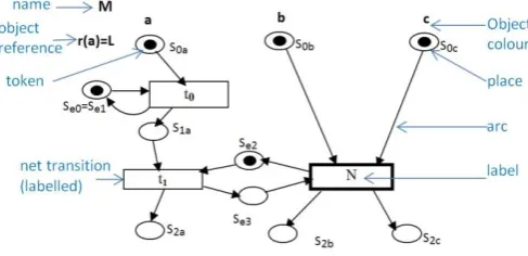
A CPN describes the states of a system using the element place and the operations that cause the model to change its state using the element transition (we called net transition). A CPN graphically shows the places using circles and transitions by rectangles. Directed arrows (arcs) are used to connect places and transitions and vice versa. Places may contain tokens represented by black dots. Each place and a token have a colour that denotes its associated object type [7, 8].
Fig. 2. CPN representing the decomposition behaviour.
As shown in Fig. 2, the CPN named M contains four object types (colours) namely a, b, c, and e, (denotes environment object). Each initial place S0a, S0b,S0c and environment places Se0 andSe2 contain one token of its object type. There are three net transitions with labels t0, t1 and N (refers to another diagram name). As we have defined in [12], the colour a is associated with an object reference to another CPN named L, given by r(a) =L. A transition fires when it acquires the required tokens. This shows the object types involved in the transition. Arcs show the flow of the model; for example transition t1 is enabled after transition t0 has fired and when it pass the token of colour a to place S1a.
III. MODEL TRANSFORMATION FROM SD TO CPN
A. Basic Transformations
[image:2.595.29.279.288.395.2]Fig. 3. A SD showing decomposition behaviour.
Each sending event, message, receiving event triple in a SD (defined as local transition [11]) is mapped to a corresponding net transition in the CPN. The net transition labels (t0, t1) correspond to message labels (m0, m1). The previous and next state locations for the instances involved in the local transitions are mapped onto places with corresponding colours in the CPN and arcs link places and the net transition as expected to keep the flow. Environment instances are involved in interactions via gate events. When transforming a local transition with a gate, equality is imposed between the places (Se0, Se1) correspond to the initial and end environment state locations.
B. Partial and Incremental Transformations
It may be required to analyse only a part of a design model for a given time during the software system development. Here, a set of interactions can be separated and applied partial transformations to obtain the corresponding target model. Also if an extension is required for a source model, new interactions can be added and use incremental transformations to synthesise the integrated target model. This process reuses the models, thus in long term it reduces the associated time, effort and cost.
Here, we mainly consider composition behaviour using ref fragment. When a SD refers to a set of interactions in another SD using a ref fragment, a single composite SD with the entire behaviour of interactions can be obtained as follows.Consider SD M in Fig. 3, which refers to SD N shown in Fig. 4, using ref fragment. When composing the two diagrams, the ref fragment is replaced by the behaviour of the referred diagram and the resulted model SD MN is shown in Fig. 5. The composite SD contains the union of the elements from both the SD with the abstract representation and the SD with the referred behaviour, except for the ref fragment and its associated events and state locations. Thus, the composition model SD MN contains all the messages m0, m1, m2 and m3.
The composite SD is obtained by imposing equality between the state location before the beginning of the ref fragment and the initial state location of the referred SD, for a given instance involved in the fragment such that S0b=S0b’ and S0c=S0c’ in SD MN. Similarly, there is equality between the state locations after the end of the ref fragment and the end state location of the referred SD, for all the instances involved in the fragment (S2b=S3b’ andS2c=S2c’). If a message connects to the ref fragment through a gate event, then the referred SD also contains a corresponding message (m1). In the composite SD there is equality between these messages and removes the associated events and state locations of environment instance.
Fig. 4. Referred SD and corresponding CPN.
Fig. 5. A SD showing composition behavior.
When transforming a SD with ref interaction fragment (SD M in Fig. 3) to the corresponding CPN (CPN M in Fig. 2), the CPN includes an additional net transition to represent the abstract behaviour given by the ref fragment. This net transition is labeled by the name of the referred diagram given by the ref fragment; in this case it is named by N. Here, the transition is in effect a substitution transition, which conveys the behaviour of the referenced CPN (CPN N in Fig. 4).
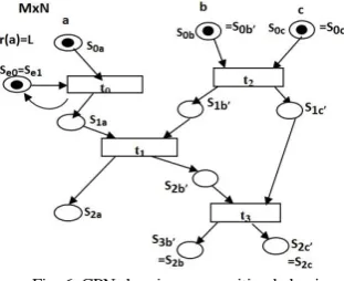
[image:3.595.49.279.42.181.2]Consider SDs with decomposition behavior using ref fragment (SD M that refers to SD N). The corresponding CPN (CPN MxN in Fig. 6) for the composition of the two SDs can be obtained by unfolding the SDs. We impose an equality between the CPN places that correspond to the state location before the beginning of the ref fragment and the initial state location of the referred SD (S0b=S0b’ and S0c=S0c) for each instances (b and c) involved in the ref fragment. Similarly, there is equality between the places that correspond to the state location after the end of the ref fragment and the end state location of the referred SD (S2b=S3b’ andS2c=S2c) for each instances involved in the fragment.
Fig. 6. CPN showing composition behaviour.
[image:3.595.354.510.549.676.2]message. In the integrated CPN (MxN) there is equality between the corresponding net transitions (t1). Also it does not have places linked to that transition for the object type corresponds to the environment instance.
Moreover, consider the CPN M in Fig. 2, that refers to the CPN N in Fig. 4, by the label of the composite net transition N. The composition of these models, CPN MxN in Fig. 6, can be obtained as follows. It contains the union of the colours, places, net transitions of both source CPNs, except for the composite net transition that refers to the other model and the places of the colour environment that are linked with that net transition. i.e. the places Se2,Se3 in CPN M and Se0’,Se1’ in CPN N that linked with the transition t1 do not contain in the integrated
CPN MxN. There is only one net transition to represent this
common net transition t1. Also there is equality between the source and the target places of the composite net transition, with the initial and end places of the referred model, respectively, for each colour.
IV. MODEL COMPOSITION
[image:4.595.383.516.226.317.2]When modelling systems with a large number of interactions it is important to be able to decompose a large SD model into smaller units making use of an interaction-use (ref fragment) or lifeline decomposition, so that each sub-model can be analysed separately. Conversely, it may be necessary to compose SD models to a single model to have a more global view of a system model. Thus, complex and large scale software systems are usually developed by a set of interconnected models with the use of composition and decomposition techniques.
Fig. 7. SD to CPN transformation paths for complex behaviour.
Previous section has described the transformation rules for the reference behaviour allowing partial synthesis of model transformation from SDs to CPNs. There are several ways to transform complex SDs into CPNs as shown in Fig. 7. Given a sequence diagram SDA with one or more references to SDB, following transformations can be done.
Transform both SDs into appropriate CPNs obtaining CPNA and CPNB where CPNA is a complex CPN with some reference (composite net transition) to CPNB. These CPNs can be analysed directly or if intended, a composite CPN can be obtained through CPN composition rules (replace the occurrences of CPNB in CPNA and obtain CPNAxB);
Compose SDA and SDB applying SD composition rules (replace the occurrences of SDB in SDA ) and use basic rules to obtain a composite CPN from SDAxB; Apply the unfolding of SDB in SDA directly obtaining
the composite CPN.
A unique CPN model CPNAxB can be obtained from each path of transformations, i.e. the diagram of Fig. 7, is preserved and confirms the correctness of transformations.
A. Mathematical Proof
In this context we need to identify the set of interactions (we called as regions) in a SD that can be separated and represented with decomposition behaviour and applied partial transformations.We define a region as a set of local transitions and the associated events, state locations and instances. Fig. 8, diagrammatically shows the regions of a model in state space and we define a region as follows.
[image:4.595.74.246.405.464.2]Definition 1: Let SDd be a sequence diagram. A region of SDd is given by SDRi; SDRi⊆ SDd, for i ∈ N.
Fig. 8. Regions of a model in state space.
The universal set SD is the sample space that contains all possible regions of a considered model. Let SDRi for i ∈ N be an arbitrary region in a considered SD. Let CPNi be the corresponding CPN of a region i, and the notation represents a transformation. In general, for a continuous model we can have;
We can make an approximation for a discrete model such that
By applying partial transformation for a given region we can obtain the corresponding CPN such that (SDRi) = CPNi. Since SDRi⊆ SD the transformation for the entire model can be represented as follows:
Further, in incremental transformation we consider the hierarchical view of a model by considering further fine-grained (smaller) sub components over the coarse-fine-grained components (regions). We represent these sub components using the ref interaction fragment. i.e., a region can contains a set of sub components and given sub component can be shared by different regions for a given time. Fig. 9 and Fig. 10, show sub sections of a region and hierarchical view of the regions, respectively. Thus a given SD consists of set of regions and a given region SDRi contains a set of ref interaction fragments.
Fig. 9. Sub sections of a region.
Fig. 10. Hierarchical view of the regions of a model.
The transformations of sub components can be shown similar to the proofs for the partial transformation of regions and the incremental transformation with model composition, as follows.
Let refk be an arbitrary reference fragment in the region SDRi and the corresponding CPN representation CPNik. In general for a continuous model we can have;
We make an approximation for a discrete model such that m
k=1 refk = SD; for k, m ∈ N+.
For a given SD, Let SDRi be a coarse-grain region of the SD model. Then mi=1 SDRi = SD; for i, m ∈ N+. Since SDRi⊆ SD and refk⊆ SDRi We can have SDRi =
p
k=1 refk ; for p ∈ N+. By applying partial transformation for a given ref sub component the corresponding CPN can be obtained such that (refk) = CPNk. The composition of CPN sub models that are obtained using partial transformation of ref fragments can be represented as follows:
Thus, it can be shown that the transformation of a given SDR region can be obtained by the integration of all the sub CPN models generated through the partial transformation of ref sub components.
Similarly, we can show this property holds for the hierarchical view of a model as follows.
Similarly, we can show the incremental transformation property is held for the composition of models. Let SDxy be an the composition of arbitrary sequence diagrams SDx and SDy and CPNx and CPNy be the corresponding CPN models and i, j, n, m, k, l, p, q ∈ N+.
V. RELATED WORK
Many efforts have been aimed at model transformation and composition [16-20]. An interesting work has been done in [17] to transform UML sequence diagrams into free choice Petri nets. They have proposed that the transformation process should start by decomposing a SD into blocks and mapping them into Petri net blocks, each with a placeholder in which another Petri net block can be substituted. This transition has considered in three phases, namely decomposition (identify the model elements preserving the causality order), transformation and composition (morph and substitute). However, they have defined transformations in a diagrammatic way considering only the event flow of the system and not the data flow of the system. They have proved the correctness of transformation using labelled event structure as a common semantic domain to capture an identical behaviour in two models.
Formal semantics for most concepts of SDs by means of Petri nets has been introduced in [18]. The authors have shown the partial ordered and concurrent behaviour of the diagrams naturally within the Petri net in a graphical way. An approach for the composition of transformation is done in [19] that guarantee the validity of the transformation chains. They have considered the transformation of UML class diagram to a relational model. Another formal approach for the composition of model transformation is presented in [20] for the mapping between typed graphs and semantic domains. They have considered the mapping of activity diagram to Communicating Sequential Process (CSP) using graph transformation rules.
transformation and composition of UML sequence diagrams to CPNs considering complex behaviours using formal exogenous transformation rules.
A formal model transformation from scenario based models to formal models considering their complex behaviour is defined in our previous work [11-12]. We have defined formal rules that explicitly state the mapping between UML SDs and CPNs that can handle object oriented features. Also we have shown that the defined languages for both models are strongly consistent, hence the transformations are free of implied scenarios. The transformations are supported by an automated tool [13, 14] and have applied to many application domains [13-15, 21]. In this paper we have contributed to a scalable approach for formal analysis of scenario-based considering model composition and decomposition and by enabling partial and incremental analysis on a model.
VI.CONCLUSION
Software design models are ideal for abstraction and handling software system with large scale and high complexity. This paper has presented model transformations based on composition and decomposition of sequence diagrams and coloured Petri nets and proved its correctness. The novelty of our approach lies in the safe composition of model transformation framework common in model-driven development considering the decomposition techniques of a SD and used partial and incremental transformations that enable local analysis as well as a global view of the system. We have introduced the notion of a region in a sequence diagram that can be replaced with a reference (lifeline decomposition or ref interaction use). Thus, partial transformations can be applied only to a region in a sequence diagram and also can be reused the synthesized region extending software design models, if required. Moreover, this framework contributes to a scalable approach for formal analysis of scenario based specifications. As future research directions we plan to investigate the applicability of partial and incremental transformations that are proven to be correct when there is a large variability in the target model or when the semantic variability lies in the source model. The model transformation correctness proofs can be generalised in order to prove correctness and completeness of related families of transformations and models. Another consequence of this work is to perform formal analysis of the synthesised models that allows system verification.
REFERENCES
[1]. A. Kleppe, J. Warmer and W. Bast, MDA Explained: The Model Driven Architecture: Practice and Promise, Addison-Wesley Object Technology, 2003.
[2]. T. Stahl, M. Volter, J. Bettin, A. Haase and S. Helsen, Model Driven Software Development: Technology, Engineering, Management, John Wiley & Sons, Ltd, 2006.
[3]. S. Sendall and W. Kozaczynski, “Model Transformation - the Heart and Soul of Model-Driven Software Development”, IEEE Software, vol. 20, no. 5, pp. 42-45, 2003.
[4]. T. Mens and P. Van Grop, "A Taxonomy of Model Transformation", Electronic Notes in Theoretical Computer Science, Vol. 152, pp. 125-142, Proceedings of the International Workshop on Graph and Model Transformation (GraMoT 2005), Elsevier Science, 2006.
[5]. “OMG Unified Modeling Language: Superstructure”, V2.4.1 , URL: http://www.omg.org/spec/UML/2.4/Superstructure/PDF, 2011. [6]. J. Arlow and I. Neustadt, UML 2 and the unified process: practical
object-oriented analysis and design, Addison-Wesley, 2005.
[7]. K. Jensen and L. M. Kristensen, Coloured Petri Nets: Modelling and Validation of Concurrent Systems, Springer-Verlag, 2009.
[8]. K. Jensen, "An Introduction to the Practical Use of Coloured Petri-Nets",In: W. Reisig and G. Rozenberg (eds.): Lectures on Petri Nets II: Applications, Lecture Notes in Computer Science, vol. 1492, Springer-Verlag, pp. 237-292, 1998.
[9]. F. Mallet, M. A. Peraldi-Frati and C. André, "From UML to Petri Nets for non functional Property Verification", IEEE International Symposium on Industrial Embedded Systems, pp. 1-9, 2006.
[10].S. Bernardi, S. Donatelli and J. Merseguer, "From UML Sequence Diagrams and State charts to analysable Petri Net models", in 3rd international workshop on Software and Performance, pp. 35-45, 2002. [11].J. Bowles and D. Meedeniya, “Formal Transformation from Sequence
Diagrams to Coloured Petri Nets”, in 17th Asia Pacific Software Engineering Conference (APSEC '10), IEEE Computer Society, pp. 216-225, 2010.
[12].J. Bowles and D. Meedeniya, “Strongly consistent transformation of partial scenarios”, ACM SIGSOFT Software Engineering Notes (SEN), vol. 37, no. 4, pp. 1-8, 2012.
[13].D. Meedeniya, J. Bowles and I. Perera, "SD2CPN: A Model Transformation Tool for Software Design Models", in 2014 International Computer Science and Engineering Conference: ICSEC 2014, pp. 461-466, IEEE Explorer, 2014.
[14].D.A. Meedeniya and I.Perera, “Model Based Software Design: Tool Support for Scripting in Immersive Environments", 8th IEEE International Conference on Industrial and Information Systems (ICIIS'13), pp.248-253, 2013.
[15].I. Perera, D. Meedeniya, I. Benerjee and J. Choudhury, "Educating Users for Disaster Management: An Exploratory Study on Using Immersive Training for Disaster Management", in IEEE International Conference on MOOC, Innovation and Technology in Education (MITE), pp. 245-250, 2013.
[16].M.Sgroi, et al., “Synthesis of Petri Nets from Message Sequence Charts Specifications for Protocol Design”, in Design, Analysis, and Simulation of Distributed Systems (DASD’04), pp. 193-199, 2004.
[17].M. A. Ameedeen and B. Bordbar, “A Model Driven Approach to Represent Sequence Diagrams as Free Choice Petri Nets”, in 12th International IEEE Enterprise Distributed Object Computing Conference, pp. 213-221, 2008.
[18].C. Eichner, H. Fleischhack, R. Meyer, U. Schrimpf and C. Stehno, "Compositional semantics for UML 2.0 sequence diagrams using Petri Nets", in Lecture Notes in Computer Science, SDL 2005: Model Driven Systems Design: 12th International SDL Forum, Vol. 3530, pp. 133-148, 2005.
[19].F. Heidenreich, J., Kopcsek and U. Assmann, “Safe composition of transformations”, in ICMT 2010, LNCS, vol. 6142, pp. 108 -122, Springer-Verlag, 2010.
[20]. D. Bisztray, R. Heckel and H. Ehrig, “Compositionality of Model Transformations”, Electronic Notes in Theoretical Computer Science, vol. 236, pp. 5-19, Elsevier, 2009.