A Sophisticated Algorithm for Using Fuzzy
Logic Controllers in Adaptive Cruise Controller
Systems
Mohsen Padash
1,∗,
Mahdi Tavassoli
2,
Abdollah Khoei
1,
Khayrollah Hadidi
11Microelectronics Research Laboratory, Urmia University, Urmia, Iran
2Department of Electrical Engineering, Shahid Beheshti University, Tehran, Iran
∗Corresponding Author: [email protected], [email protected]
Copyright c⃝2013 Horizon Research Publishing All rights reserved.
Abstract
Using fuzzy logic controller, a sophisticated algorithm for adaptive cruise controller systems is pro-posed. The presented architecture can control the vehicle acceleration in a very simple and efficient way. The new algorithm is simulated in an artificial environment using MATLAB. In comparison with previous works, simulation results of the proposed algorithm have a much smoother output for controlling throttle and brake actuator of a car. In addition we represent a structure for implementing the proposed algorithm by using FLC, DAC, ADC, adders and some digital gates.Keywords
Adaptive Cruise Controller, Fuzzy Logic Controller, Intelligent Transportation Systems, MATLAB Simulation1
Introduction
From old days the transportation systems have been one of the most significant aspects of our life. Today’s rapid increasing of traffics in roads, the most frequent driving scenario [1], demands enormous increasing of intelligent transportation systems (ITSs). One of the applications of ITS is to provide the assistance to the control of some of the vehicle elements, like the throttle pedal and consequently, the speed-control assistance [2]. Adaptive cruise control (ACC) system is a new generation of conventional cruise control systems. But, unlike the conventional cruise control structures, this new system can automatically adjust the speed in order to maintain a proper headway distance (gap) between vehicles in the same lane [3,4]. This is achieved by using a radar headway sensor such as lidar [5], a digital signal processor, and an intelligent speed control system [6]. If the front vehicle slows down, or another obstacle is detected, the ACC sends a signal to the engine and the braking system decelerates the vehicle. On the other hand, when the front vehicle speeds up, or no obstacle is detected, the ACC will re-accelerate the vehicle back to the default speed [7,8]. Because of the ability of fuzzy logic controller (FLC) in mimicking human behaviour, it can be used as a good bridge to achieve this goal.
The fuzzy control method was first introduced by Lotfi Zadeh for systems which are difficult to control using conventional methods. It is based on the work of Zadeh on fuzzy sets [9]. FLCs have been used in many applications of intelligent transportation systems, C. Kim [10] used fuzzy logic-based method to make an optimal decision for an autonomous vehicle, design of adaptive neurofuzzy inference system (ANFIS) models for predicting the future of the stop & go is presented in [11], J. E. Naranjo [12] used FLC to imitate the driving behavior of human. All the papers on fuzzy-based ACCs, apply the FLC output directly to the throttle or brake as an input signal. The abrupt changes in FLC output signal causes depredation in mechanical hardware. In order to avoid the abrupt changes, the new algorithm of controller uses an adder after the FLC. Therefore the final output of the controller becomes smoother by integrating the FLC output.
MATLAB simulations are presented to verify the new structure’s ability in controlling the vehicle speed in different situations.
2
Paper Outline
In the following section we describe the proposed ACC algorithm . The algorithm implementation is explained in section 4, and section 5 describe the MATLAB simulation of the proposed algorithm. Finally, in section 6 we conclude the paper with a discussion of results.
3
Proposed Algorithm
The proposed algorithm for ACC controller has the ability to control the maximum acceleration of the vehicle, it has three inputs and one output. The input signals are ∆dt, ∆sand ∆v. They are defined as follows:
∆dt = distance f rom the f ront vehicle (1)
∆s = vehicle real speed − desired speed (2)
∆v =
(
∆dt−∆d(t−∆t)
)
∆t
(3) Vehicle real speed comes from a hall sensor, While a radar headway sensor or a lidar gives us the distance from the front vehicle. In (2) thedesired speed is the speed which is set by driver. Equation (3) represents reletive speed of the two vehicles, ∆dt is obtained form (1) and ∆t is the time variation steps that we consider for obtaining
[image:2.595.96.518.372.747.2](3). Fig. 1 illustrates the algorithm used to control the vehicle speed in different situations. The vehicle speed is restricted by controlling the throttle input signal.
Figure 1. Proposed algorithm for controlling vehicle speed.
The algorithm of Fig.1 puts a desired upper limit on the value of positive acceleration, a typical value of 2m/s2
cruise control. Under cruise control, the system’s goal is to reach the pre-set speed. In order to achieve this goal, the system checks ∆s and if it is not zero, it adjusts the throttle control pressure until the speed error becomes
zero. If there is a vehicle ahead, in this situation ∆dt is less than 250 meter, the speed of our vehicle must follow
the speed of the front vehicle. In this state the vehicle is in adaptive cruise control mode.
4
Algorithm Implementation
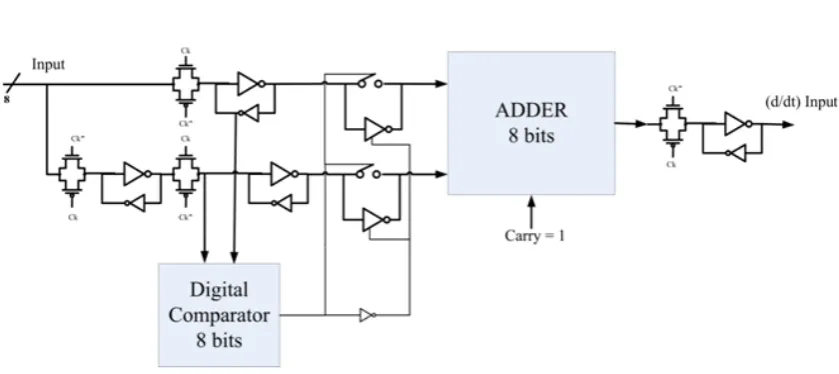
[image:3.595.88.500.370.435.2]Block diagram of implementing the proposed algorithm is depicted in Fig. 2. The basic idea behind our structure is to reduce the abrupt changes of the throttle control signal. This is achieved by integrating the FLC output using a 10-bit adder right after the FLC block. As shown in Fig.2, to perform the algorithm, a 4-bit analog to digital converter (ADC) and a 9-bit digital to analog converter (DAC) are required too. As suggested by Fig. 1, we need to add or subtract the FLC output from the previous value. First we determine if the FLC output is a positive value or a negative one. If the FLC output is more than fifty percent, it is considered positive and must be added to the previous output value. Otherwise, it is considered negative and must be subtracted from the previous output value. When there is no error, the FLC output would be exactly the half of the maximum desired value. A 4-bit ADC is used to convert the analog FLC output into digital. The most significant bit (MSB) of the ADC output is the sign bit. If it is one then the FLC output is positive and it must be added to the previous output value, otherwise it is a negative value and must be subtracted from the previous output value. In order to subtract two digital numbers using an adder, the carry value has to be set to one. The final output is a 10-bit digital value. Therefore, a 10-bit adder is needed to add or subtract the FLC output from the previous value. The upper limit of the vehicle acceleration signal (ULVAS) is shown in Fig. 2. If the acceleration reaches the upper limit of the vehicle acceleration, the ULVAS in Fig.2 goes high. Consequently, the adder block adds zero to the previous value. If the acceleration becomes less than the upper limit of the acceleration value, the ULVAS goes low. Therefore the adder adds the output of the ADC to the previous output value.
Figure 2. Implementation of the proposed algorithm.
Figure 3. ∆vimplementation.
The MSB of the output value is the sign bit. If the MSB is one then the other nine output signals are digital signals for controlling the throttle of vehicle. Otherwise the inverted state of the other nine output bits are the brake system controlling signals. This strategy guarantees the use of only one actuator at a time either the throttle or the brake actuator. As a result, less fuel is consumed. Finally a 9-bit DAC converts the digital signals to two analog voltages which control the throttle and the brake system. These voltages can be substituted for the throttle and brake control voltages, which are produced by the gas and the brake pedal, under manual control. By choosing either ∆dt or ∆s as the inputs of the structure in Fig. 3, the value of velocity and acceleration can be produced
[image:3.595.81.501.464.651.2]produces. The level of output current signal of this sensor is about 7mA for low state and 14mA for high state [13]. After amplifying this signal and passing it through the two inverter blocks, we have a square wave that can be used as an input clock for a digital accumulator to count the speed of the vehicle.
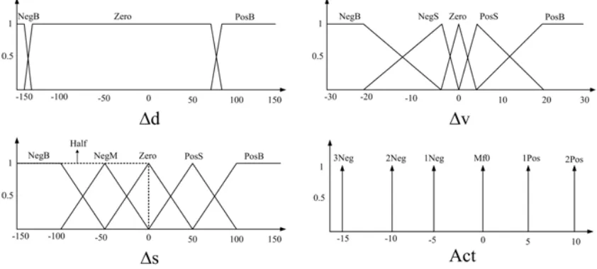
Figure 4. The membership functions for the ACC system.
5
MATLAB Simulation of the ACC Algorithm
Figure 4 shows the membership functions of the FLC which are designed in MATLAB. We use 11 rules to implement the proposed algorithm. The rules are defined as following:
If ∆s is Half and∆d is Zero and∆v is N egB
then Act is 2N eg (4)
If ∆s is Half and∆d is Zero and∆v is N egS
then Act is 1N eg (5)
If ∆s is Half and∆d is Zero and∆v is Zero
then Act is M f0 (6)
If ∆s is Half and∆d is Zero and∆v is P osS
then Act is 1P os (7)
If ∆s is Half and∆d is Zero and∆v is P osB
then Act is 2P os (8)
If ∆s is N egB and∆d is N egB
then Act is 2P os (9)
If ∆s is N egS and∆d is N egB
If ∆s is Zero and∆d is N egB
then Act is M f0 (11)
If ∆s is P osS and∆d is N egB
then Act is1N eg (12)
If ∆s is PosB and∆ d is NegB
then Act is2N eg (13)
If ∆d is P osB
then Act is3N eg (14)
The MATLAB 3D surfaces related to these rules is shown in Fig. 5. and Fig. 6.
Act
∆d
[image:5.595.160.402.267.461.2]∆v
Figure 5. MATLAB Fis first surface.
Act
∆d
∆s
Figure 6. MATLAB Fis second surface.
The ACC system including FLC, the mentioned blocks for completing the algorithm and the Simulink model of vehicle, the blue box, is shown in Fig. 7. Two cars are needed in this simulation. The Simulink model of vehicle which is available in the demos of MATLAB [14] is used for the first car. For the second car an arbitrary velocity pattern can be chosen. The position and the velocity of both cars are related by the following:
[image:5.595.169.402.505.700.2]Figure 7. The total ACC schematic in MATLAB Simulink.
T hrottle Control
Engine RP M
V ehicle Speed
V ehicle Acceleration
[image:6.595.116.494.383.750.2]By subtracting the current position of the two cars, the distance between the two vehicles is obtained. In Fig. 8. the simulation results of MATLAB Simulink workspace is shown which has a very smooth signal to control the vehicle throttle position. In Fig. 8. the horizontal axis shows time in seconds. We assume that the speed of the first car is set to 100km/h and the speed of the second car is 80 km/h. The initial distance between two vehicles is 500 meter. Therefore the vehicle speeds up to 100 km/h at first. When the acceleration of the first car exceeds 2 m/s2 , the throttle input does not change until the acceleration decreases. After 220 seconds the distance between two vehicles becomes less than 250 meter. Therefore the system is in ACC mode and speed of the first car must reduce to 80km/h.
6
Conclusion
We proposed a new algorithm architecture for adaptive cruise controller applications. The simulation results show a very smooth output for controlling the throttle and brake of a vehicle. It is capable of controlling the acceleration by predetermined quantities and does not need any filter for the outputs of controller because they are made smooth enough by adding another loop in controlling structure. So in comparison with the previous works it has advantages of acceleration control and smoother controlling outputs. In addition we represent a structure for implementing the proposed algorithm by using FLC, DAC, ADC, adders and some digital gates. Although evaluation of the proposed ACC algorithm and designed FLC structure was just investigated through MATLAB simulations, it can be applied in real vehicles and good vehicle speed controlling will be expected as the simulations showed. The proposed algorithm can be used in safe distance keeping observers, collision avoidance systems, assistant driving devices and other ITS applications.
Acknowledgement
The authors would like to thank students of Microelectronics Research Laboratory of Urmia University for their helps and comments.
The author Mahdi Tavassoli was with Microelectronics Research Laboratory, Urmia University when this work was done.
REFERENCES
[1] W. Jianqiang, Z. Lei, Z.Dezhao, L.Keqiang. An adaptive longitudinal driving assistance system based on driver char-acteristics. IEEE Trans. Intell. Transp. Syst., vol. 14, no. 1, March 2013.
[2] J. E. Naranjo, C. Gonzalez, J. Reviejo, R. Garcia, T. de Pedro. Adaptive fuzzy control for intervehicle gap keeping, IEEE Trans. Intell. Transp. Syst., vol. 4, no. 2, pp.132 -142 2003.
[3] A. Vahidi, A. Eskandarian. Research advances in intelligent collision avoidance and adaptive cruise control, IEEE Trans. Intell. Transp. Syst., vol. 4, no. 3, pp.143 -153 2003.
[4] B. van Arem, C. J. G. van Driel, R. Visser. The impact of cooperative adaptive cruise control of traffic-flow character-istics, IEEE Trans. Intell. Transp. Syst., vol. 7, no. 4, pp.429 -436 2006.
[5] M. Maehlisch, R. Hering, W. Ritter, K. Dietmayer. Heterogeneous Fusion of Video, LIDAR and ESP Data for Au-tomotive ACC Vehicle Tracking, Proceedings of IEEE Conference on Multisensor Fusion and Integration, Heidelberg, Germany, 2006.
[6] H. Cheng , N. Zheng , X. Zhang , J. Qin, H. van de Wetering. Interactive road situation analysis for driver assistance and safety warning systems: Framework and algorithms, IEEE Trans. Intell. Transp. Syst., vol. 8, no. 1, pp.157 -167 2007.
[7] J. E. Naranjo , C. Gonzalez, R. Garcia, T. de Pedro. ACC + stop & go maneuvers with throttle and brake fuzzy control, IEEE Trans. Intell. Transp. Syst., vol. 7, no. 2, pp.213 -225 2006.
[8] J. J. Martinez, C. C. de Wit. A safe longitudinal control for adaptive cruise control and stop-and-go scenarios, IEEE Trans. Control Syst. Technol., vol. 15, no. 2, pp.246 -258 2007.
[9] L. A. Zadeh. Outline of a new approach to the analysis of complex systems and decision processes, IEEE Trans. on Systems, Man & Cybernetics, vol. SCM-3, no. 1, pp. 28-44, Jan. 1973.
[10] C. Kim, R. Langari. Adaptive analytic hierarchy process-based decision making to enhance vehicle autonomy. IEEE Trans. on Vehicle. Technology vol. 61, no. 7, Sep 2012.
[12] J. E. Naranjo, C. Gonzalez, R. Garcia, T. de Pedro. Cooperative throttle and brake fuzzy control for ACC + stop & go maneuvers, IEEE Trans. Veh. Technol., vol. 56, no. 4, pp.1623 -1630 2007.
[13] R. Bosch GmbH. Safety, Comfort and Convenience Systems, John Wiley & sons Press, West Sussex England, 2006.