A SATELLITE STAR IDENTIFICATION ALGORITHM
BASED ON POLAR GRID
1HUA ZHANG, 2XIAOPING JIANG, 3SHAOBO CHEN
1Lecturer, College of Electronics and Information Engineering, Hubei Key Laboratory of Intelligent
Wireless Communications, South-Central University for Nationalities, China
2
Assoc. Prof., College of Electronics and Information Engineering, Hubei Key Laboratory of Intelligent Wireless Communications, South-Central University for Nationalities, China
3Lecturer, College of Electronics and Information Engineering, Hubei Key Laboratory of Intelligent
Wireless Communications, South-Central University for Nationalities, China E-mail: [email protected], [email protected], [email protected]
ABSTRACT
In the star identification algorithms based on the inter-star angular distances, more dimensions of the star patterns are adopted to get high rate of success. However, it spends more time for star identification process. To speed up the star identification process while keeping high rate of success, a new stellate pattern composed of all of the stars in the star image is proposed. So the pattern is characterized of maximal dimension. Then a polar grid algorithm is adopted to avoid spending much time in the identification process. The simulations demonstrate that the algorithm is superior to the original grid algorithms and the triangle algorithms in rate of success, robustness to noises, computing cost and memory required.
Keywords: Star Identification, Stellate Pattern, Grid Algorithm, Polar Coordinate System, Star Sensor
1. INTRODUCTION
As one of the key technologies of the star sensor, star identification has been widely studied for decades and various star identification algorithms have been proposed and verified[1,2,3]. Theoretically, the star identification algorithms can be divided into two classes of methods: the subgraph isomorphism methods and the pattern recognition methods[4]. The subgraph isomorphism methods employ the star-pair angular distances for star recognition, such as the polygon match algorithms, the triangle algorithms and the match group algorithms[5,6,7]. To increase the rate of success, more stars are participated in identification process to increase the dimension of the patterns and eliminate the similar matches. Whereas increasing the dimension of the pattern causes the inflation of the pattern database and delays the whole process of the star identification algorithm. The other class of star identification algorithms implements star identification in terms of pattern recognition or best match, including the grid algorithms, neural network algorithms and other algorithms[8,9,10,11,12,13]. These algorithms associate each star with a pattern or signature
determined by its surrounding stars in the FOV(field of view) of the star sensor. Then the star identification process can be treated as finding the closest match between the observed patterns and the database patterns. It is observed that the pattern recognition algorithms perform better than the subgraph isomorphism algorithms in redundant and false matches. The most representative algorithm in this class is the grid algorithm[8]. Compared with the other algorithms, the grid algorithm is an excellent algorithm with higher identification rate and smaller memory requirement, as well as it is computationally efficient[9]. However, the algorithm needs to find the closest neighboring star of the reference star to generate a star pattern. As many fixed stars are variable in visual brightness and the noises exist in measurement, the identification probability for the closest neighboring star is comparatively low. That leads to misidentifications and identification failure thereafter.
maximum pattern dimension, and the pattern is equivalent to the subgraph isomorphism patterns geometrically. To speed up the star identification process, a polar grid algorithm is adopted to avoid floating point calculation in comparing the inter-star angles in the pattern database and those in the star image. The algorithm synthesizes the advantages of the subgraph isomorphism algorithms and the grid algorithms, and can be used both in lost-in-space mode and tracking mode. The simulations demonstrate that the algorithm is superior in computing cost and rate of success to the grid algorithms and the triangle algorithms.
2. THE STELLATE PATTERN FOR STAR
IDENTIFICATION
[image:2.612.322.511.447.568.2]As described in the first section, in the subgraph isomorphism algorithms such as the triangle algorithms and the polygon algorithms, the angular distances are employed for star recognition. In the algorithms, two stars make up a star pair, and the angle between the two stars is called the angular separation or angular distance of the star pair. In the subgraph isomorphism algorithms, the angular separations between the star pairs in the star image are computed and compared with those stored in the pattern database. If the differences are within an error bound on the expected errors, the angular distance patterns are considered matched and the stars made up of the star pairs can be recognized. Then the dimension of the pattern is determined by the number of stars comprising the pattern. For instance, when the pattern is comprised of three angular distances between the three stars, the algorithm is called a triangle algorithm and the dimension of the pattern is three, as shown in Fig. 1. As is known that, the higher the dimension of the pattern is, the higher rate of success the algorithm gets. Accordingly, a fourth star or more stars can be used to compose more inter-star angular features to eliminate the approximate matches and thus improve the rate of success. That yields the polygon algorithms and the pyramid algorithms. However, as the dimension of the pattern increases, the speed of the algorithm is delayed.
Figure 1: The Triangle Pattern
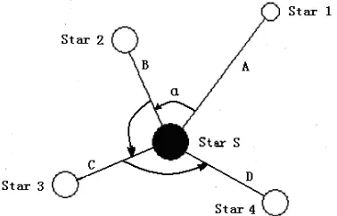
[image:2.612.131.260.629.708.2]To use the information of the distribution of the stars, we propose a stellate pattern. In the proposed pattern, a pivot star S is translated into the center of the FOV, as shown in Fig.2. Then the lines connected the star S and the surrounding stars, along with the angles between the two lines, determine a triangle. Thus the angular distances between the star S and the neighbor stars and the angles between the lines can be efficient for star identification. When more stars are to be identified, the patterns can be denoted by the angular distances and the angles between the lines. The lengths of the lines can denote the angular distances between the star S and the surrounding stars, and the angles between the lines can represent the distribution of the stars surrounding the star S. Then we can get a stellate pattern comprised of a star in the center, the angular distances between the surrounding stars and the angles between the lines. In symmetric, the stellate pattern can be converted to the polygon patterns, and vice versa. When there are only two neighbor stars, the proposed pattern is equivalent to the triangular patterns. As the relative positions of the stars in the star image are firm, the stellate pattern is of invariance of transmission and rotation, so it is suitable for star identification. Compared with the subgraph isomorphism patterns, the stellate pattern is superior in the dimension of the pattern, then it is potential to get higher rate of success and lower rate of misidentification.
Figure 2: The Stellate Pattern Is Equivalent To The Polygon Patterns Geometrically.
3. STAR IDENTIFICATION
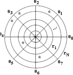
low speed and subject to the star magnitudes. As the grid algorithm does not involve floating point calculation, it is characterized of high speed and robustness. In our former work, a polar coordinate system based grid algorithm is used to speed up the star identification process[14]. As shown in Fig.3, if a pivot star is located in the origin of the polar coordinate frame, the stellate pattern can be denoted by the polar grid. Then the polar grid algorithm can be used to identify the stellate patterns without floating point calculation.
Figure 3: The Stellate Pattern Can Be Denoted By The Polar Grid
3.1 Pattern Generation
As described in document[14], the first step of the algorithm is to generate the patterns. To use the polar grid algorithms, the pivot star must be located exactly at the origin of the coordinate frame. As the locations of the stars in a star image are extracted and the centroids are calculated, the star nearest the center of the FOV is chosen as the pivot star S. A round neighbor area of the pivot star S is generated in the new polar coordinate system, with the radius of the round area covering all the stars in the FOV of the star sensor. Then the polar grids are partitioned by a mean radial angle and a mean angular distance. The positions of the stars in the star image are translated to a polar coordinate frame in which the pivot star is located in the exact origin of the frame. Then the stellate pattern can be described by the coordinates of the stars, as shown in Fig.3. To reduce the computational burden with the trigonometric computings, a lookup table(LT) is used to map the coordinates of the stars in the planar image frame to the polar coordinate system. Then the radial and angular vectors of the star image can be got.
To generate the radial-feature pattern, the round neighbor area of the star S is evenly partition into N
ring strips, where each ring strip represents a determined angular distance. The number N is determined by the location of the star S in the star image. Normally it is equal to the largest number of ring strip where there is at least one star within the
ring strip. Therefore the radial pattern of the star S can be determined by a radial vector
pat S
r( )
,1 2
( ) ( , , ..., )
r N
pat S = B B B (1)
Where
i-1 i
1, if there is at least a star between the radial
grid and ;
0, else.
i
B ϕ ϕ
=
(2)As for the angular-feature pattern, the round neighbor area of the pivot star S is evenly partitioned into m angular sectors, with each sector representing a determined angular distance in the angular direction. Then an angular vector
1 2
( , , ..., m)
v= A A A can be obtained from the neighbor stars’ distribution in the angular sectors in an anticlockwise direction, where
i-1 i
1, if there is at least one star between the
angle grid and ;
0, else.
i
A θ θ
=
(3)When two or more stars lie in the same sector, the corresponding bit of this sector is set to 1 just like the situation that only one star lies in the sector. Shift v to the left circularly to find the maximum value formed by vwhere each Ai is treated as a bit sequentially. As a result, the maximum value is defined as the angular pattern of the star S. For instances, when the angular vector includes 8 bits and there is only one star within the round area, the angular pattern of the star, pat Sa( )=128 . Especially when there is no neighbor star within the round neighbor, pat Sa( )=0.
3.2 Pattern Matching
The catalog radial pattern database is generated just as the process of generating the sensor radial pattern. To be compatible with the unusual conditions that the reference star is near the brim of the FOV, the number of N in generating the catalog radial patterns is so set that the radius of the round area is twice the size of the FOV, i.e. N=100×θ where θ is the angle of the FOV in degree. Therefore the number of the bits in a catalog radial pattern is larger than that in a sensor radial pattern. Accordingly, in the radial pattern matching process, when the numbers of the catalog radial pattern is longer than that of the sensor radial pattern, the extra bits are neglected.
anyBi=1 is true both in the sensor pattern and in the catalog pattern, the likeness counter plus one. The counter remains invariable whenever Bi=0 or the responding
B
i in the sensor pattern is not as same as that in the catalog pattern. The star with the highest counter value is considered as the candidate star. In the same way, for every angular pattern in the catalog, if any bit equals to one both in the sensor angular pattern and in the catalog angular pattern, the likeness counter plus one. As the angular distribution of the neighbor stars is invariant of rotation, the sensor angular pattern is shifted circularly till a maximal likeness counter value is gotten. And the star with the highest counter value is considered as the coarsely-matched star. Then the angular separations among the stars are computed to make sure exactly which star is in the FOV.3.3 Star Identification
The star identification process adopts the advantages of the grid algorithms. The algorithm includes the steps as follows:
(1) Pivot star selection and coordinate frame building
Choose a brightest star S near the center of the FOV as the pivot star and the polar origin, then a polar coordinate frame is built around the pivot star S.
(2) Pattern generation and pattern matching A round area around the star S is generated and partitioned into N ring strips and m angular sectors, as described above. The sensor radial pattern is generated and matched with the patterns in the pattern database. If there is only one candidate star, the identification process is complete. The candidate star is considered as the coarsely-matched star, and the algorithm goes to next step. Otherwise, if there are more than one candidate stars, the angular pattern is generated and matched.
(3) Angular separation verification
If there is only one coarsely-matched star, the angular separations between the neighbor stars and the pivot star are computed and checked with the angular separations in the catalog to distinguish each star. If there is more than one coarsely-matched star, the angular separations among the neighbor stars are computed to eliminate the false coarse matches. Then the angular separations between the neighbor stars and the pivot star are computed and checked to distinguish each star.
4. THE SIMULATIONS
To evaluate the performance of the proposed
algorithm, simulations are conducted on the virtual photos taken on the full celestial sphere, with various noises inserted into the stars in the virtual star images. The algorithm is compared with the triangle algorithm and the original grid algorithm in[8] under the same condition. The FOV of the star sensor used for simulation is 18°×18°, with the star image resolution of 1024 ×1024 pixels. The stars brighter than 6.0Mv are selected as the potential pivot stars. For the proposed algorithm, the radial angular distance between the ring strips is set to 0.01°and the radius for pattern generation is 10°. All the algorithms are performed in a PC with the processor Intel Pentium (R) 1.6G.
(1) Simulation with position errors
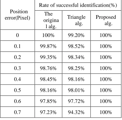
[image:4.612.317.519.420.618.2]To evaluate the rate of success of the algorithms in various position errors, random white noise is inserted to the positions of the stars in the star images, with the mean zero and the standard deviation from 0.1 pixels to 0.7 pixels. The rates of success of the three algorithms with various noises are listed in table 1. As shown in table 1, when the noise of the position rises, the rate of success in the proposed algorithm keeps high, and that of the reference algorithms decrease. That means that the algorithm is robust to the position noise.
Table 1: Rate of Success In Various Position Errors
Position error(Pixel)
Rate of successful identification(%)
The origina
l alg.
Triangle alg.
Proposed alg.
0 100% 99.20% 100%
0.1 99.87% 98.52% 100%
0.2 99.35% 98.34% 100%
0.3 98.76% 98.25% 100%
0.4 98.45% 98.16% 100%
0.5 98.16% 98.01% 100%
0.6 97.85% 97.72% 100%
0.7 97.23% 94.32% 100%
(2) Simulations with magnitude errors
Table 2: Rate of Success In Various Magnitude Errors
Magnitu de error (Mv)
Rate of successful identification(%)
Original grid alg.
Triangle alg.
Proposed alg.
0 98.45% 98.27% 100%
0.5 98.15% 95.32% 100%
1.5 94.42% 94.74% 99.87%
2.0 91.28% 92.72% 99.51%
2.5 84.23% 89.42% 99.14%
As shown in table 2, when the star magnitude noise rises, the rates of success of all the three algorithms decrease. For the noises in star magnitude affect the selection of the neighbor stars, they affect the performance of the algorithm. As the noise cannot change the distribution of the stars in the star image, the noise have little effect on the proposed algorithm and the triangle algorithm. (3) Simulations with false star existence
As is known, the stars extracted from the star image may not be accordance to those in the real FOV. The faint stars may not be extracted and some noise and objects maybe extracted as a star. That cause false stars and lost stars. If the number of the stars in the FOV is enough, the lost stars may not be important. But the false stars may affect the performance of the identification algorithm.
To evaluate the influence of the false stars on the rate of success of the algorithm, random false stars are inserted to the star images. The star magnitudes of the false stars are set to 5.0Mv. The influence of the number of false stars on the rate of success is listed in table 3. In the table, the false stars have effect on the triangular algorithm, for the dimension of the algorithm is lower, and the false stars result in false angular distances which lead to identification failure or false identification. However, the proposed algorithm and the original grid algorithm are robust to the false stars. For all the stars in the FOV take part in the identification process, the dimension of the pattern is high.
Table 3: Rate of Success With False Stars
Number of false
stars
Rate of successful identification(%)
Original grid alg.
Triangle alg.
Proposed alg.
0 99.77% 99.20% 100%
1 99.75% 97.23% 100%
3 99.57% 94.55% 99.97%
5 99.68% 90.16% 99.71%
7 98.87% 84.94% 99.84%
(4) Simulations with the number of stars
As described above, all the stars are involved in the star identification process in the proposed algorithm, so the pattern has a maximum dimension. However, as the distribution of the fixed stars in the real sky is not uniform. In some directions, the number of the stars in the FOV is small, which must affect the performance of the algorithm.
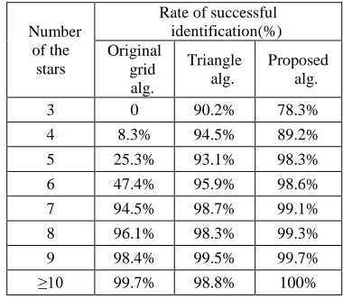
[image:5.612.321.511.464.635.2]To analyze the influence of the number of the guide star, the FOV of the star sensor used for simulation is changed to 10º×10º, the random position noise and false star is injected to the star image. The rate of success for the algorithm is listed in table 4. As in table 4, when the number of the stars reduces to lower than 10, the rate of success of the algorithm proposed and the original grid algorithm decrease, but it has no effect on the triangle algorithm. That means that, when the number of the stars decrease, the grid algorithms no longer have the dimensional advantage, then the approximate matches cannot be eliminated. In the proposed algorithm, a verification process is added, that improves the performance in fewer stars. But it is interior to the triangle algorithm when the number of the stars is lower than 5. As shown in table 4, the algorithm proposed needs more than 5 stars, requiring that the star sensor has high star detectability.
Table 4: Rate of success in various star numbers
Number of the
stars
Rate of successful identification(%) Original
grid alg.
Triangle alg.
Proposed alg.
3 0 90.2% 78.3%
4 8.3% 94.5% 89.2%
5 25.3% 93.1% 98.3%
6 47.4% 95.9% 98.6%
7 94.5% 98.7% 99.1%
8 96.1% 98.3% 99.3%
9 98.4% 99.5% 99.7%
≥10 99.7% 98.8% 100%
5. DISCUSSION AND ANALYSIS
5.1 Analysis of The Memory and
Computational Requirement
composed with 3 angular separations. Then if there
are N stars in the star image, there may be C3N
patterns. As the angular separations are denoted by double floating point data, the memory required for storing the optimized catalog patterns of the triangle algorithm used in simulation is about 1MB.
As in the proposed algorithm and in the grid algorithms, there is only one pattern for a pivot star. The pattern numbers in the algorithm is equal to the number of the guide stars. The memory for storing the catalog patterns is proportional to the number of the stars and the memory for a single pattern. As mentioned above, the memory needed for a single pattern is determined by the size of the grid. The smaller the grid is, the larger the memory is. For the original grid algorithm, a single pattern need
8
pixel pixel
N N
M
d d
× =
× × bytes to store the pattern, where
pixel pixel
N ×N is the resolution of the star image,
d×dis the grid size. Comparably, in the proposed algorithm, the memory for a single pattern is
8 R M
δ
=
× +1 bytes, where R is the diameter for
round area in angular degree and δ is the grid size. As the patterns in the grid algorithms can be suppressed by using character suppressing methods, the memory required for grid algorithms can be reduced. In the proposed algorithm, the round area is 10°, and the grid size is 0.01°. The memory needed is about 235KB. Comparably, the memory required for the original grid algorithm with grid size 20×20 is about 140KB. The algorithm proposed needs more memory than the original grid algorithm.
As for the computational load for the algorithm, the patterns used in the proposed algorithm and the original grid algorithm are denoted by binary vectors. Then the computation in the star identification process can be simplified to logical computations. So they are characterized of simple computation. As is known, in the angular separation based algorithms, each angular separation comparison involves a float point addition computation. Thus a single pattern matching process needs several floating point calculations, which are more than that needed for the algorithm proposed. Moreover, the number of the patterns in the proposed algorithm is equal to the number of the pivot stars, while the patterns in the angular separation based algorithms are comprised of several stars. Thus the number of the proposed patterns in the proposed algorithm is less than that of the angular separation based algorithms.
Therefore, the matching times in the proposed algorithm are less than those of the triangle algorithm. Time spent in the algorithms used in the simulations is listed in table3.5. Where the position errors are within 0.4pixel, and the star magnitude errors are within 0.5Mv. As in table 5, the proposed algorithm is characterized of high speed.
Table 5: Average Time The Algorithms Spend
average time spent(ms) Original grid
alg. Triangle alg. Proposed alg.
14.52ms 21.70ms 9.31ms
5.2 Discussion of The Algorithm
As described in section 3, the pattern in the proposed algorithm can be denoted by the pivot star in the center of the grid. The algorithm can be used in tracking mode, as well as in lost-in-space mode. When the star sensor is working in tracking mode, the initial boresight of the star sensor is known. Then the potential stars in the FOV of the star sensor can be determined within a limited spatial area. Then the pattern can be compared with a limited numbers of stars in the database. Then the time costing is reduced.
As the simulations demonstrate, the algorithm is characterized of high rate of success, high speed, smaller memory requirement and robustness to the noises and errors. Moreover, as more stars in the star image are recognized in the algorithm, it is beneficial to the precision of the attitude computations.
6. CONCLUSIONS
ACKNOWLEDGEMENT
This work is supported by the Fundamental Research Fund for the Central Universities, South-Central University for Nationalities, China under Grant No. CZQ11017, the open fund of Hubei Key Laboratory of Intelligent Wireless Communications under Grant No. IWC2012014, the Key Technologies R&D Program of Wuhan City, China under Grant No. 201110821229, the General Program of the Natural Science Fund of Hubei Province, China under Grant No. 2012FFC13301 and the General Program of National Natural Science Foundation of China under Grant No. 61201448.
REFRENCES:
[1] C.C. Liebe, "Star trackers for attitude determination," IEEE Aerospace and Electronics Systems Magazine, Vol. 10, No. 6, 1995, pp. 10-16.
[2] C. Padgett, K. Kreutz-Delgado and S. Udomkesmalee, "Evaluation of star identification techniques," Journal of Guidance, Control and Dynamics, Vol. 20, No. 2, 1997, pp. 259-267.
[3] C.C. Liebe, "Accuracy performance of star tracker-a tutorial," IEEE Transactions on Aerospace and Electronic Systems, Vol. 38, No.2, 2002, pp. 587-589.
[4] B. Benjamin, I. V. Spratling, and D. Mortari. A Survey on Star Identification Algorithms. Algorithms, No. 2, 2009, pp. 93-107.
[5] D. Mortari, M. A. Samaan, and C. Bruccoleri, et
al, "The pyramid star identification technique,"
Journal of The Institute of Navigation, Vol. 51, No. 3, 2004, pp. 171-184.
[6] M.A. Samaan, D. Mortari, and J.L. Junkins,
"Recursive-mode star identification
algorithms," IEEE Transactions on Aerospace and Electronic Systems, Vol. 41, No. 4, 2005, pp. 1246-1254.
[7] C.L. Cole, J.L. Crassidis. Fast Star Pattern Recognition Using Planar Triangles. Journal of Guidance, Control, and Dynamics, Vol. 29, No. 1, 2006, pp. 64~71.
[8] C. Padgett and K. Kreutz-Delgado, "A grid algorithm for autonomous star identification," IEEE Transactions on Aerospace and Electronics Systems, Vol. 33, No.1, 1997., pp. 202-213
[9] H. Lee, H. Bang. "Star Pattern Identification Technique by Modified Grid Algorithm," IEEE Transactions on Aerospace and Electronic
System, Vol. 43, No. 3, 2007, pp. 1112-1116. [10] G. Zhang, X. Wei and J. Jiang, "Full-sky
autonomous star identification based on radial and cyclic features of star pattern," Image and Vision Computing, Vol. 26, No. 7, 2008, pp. 891-897.
[11] M. Na, D. Zheng and P.F. Jia, “Modified Grid Algorithm for Noisy All-Sky Autonomous Star Identification,” IEEE Transactions on Aerospace and Electronic system, Vol. 45, No. 2, 2009, pp. 516-522.
[12] G. Zhang, X. Wei and J. Jiang, “Full-sky autonomous star identification based on radial and cyclic features of star pattern,” Image and Vision Computing, Vol. 26, 2008, pp. 891-897. [13] J. Hong, J. A. Dickerson,
“Neural-network-based autonomous star identification algorithm,” Journal of Guidance, Control & Dynamics, Vol. 23, 2000, pp. 728-735.
[14] H. Zhang, H.S. Sang and X.B. Shen, “A polar coordinate system based grid algorithm for star identification,” Journal of Software Engineering and Applications, Vol. 3, No. 1, 2010, pp. 34-38.