© 2017, IRJET | Impact Factor value: 5.181 | ISO 9001:2008 Certified Journal | Page 247
AUTONOMOUS EYE
1
Ms. Reshma K.V,
2Ajin V Alex,
3Aswathy S,
4Ditto Davis
1Assistant. Professor, 2,3B.Tech Final Year Students
1,2,3,4Dept of computer Science and Engineering, Jyothi Engineering College, Keral, India
---*****---Abstract: Autonomous Eye is a powered wheel chair system, its movement is controlled using the eye movements. The system is implemented mainly for the paralyzed persons. The system helps the disabled persons to move independently. The system consists of a wheelchair, RF modem and a PC, which is connected to a webcam[12]. User’s eye movements are converted to screen position using matlab software. When user looks at appropriate direction, using some image processing techniques the computer system will detect the direction, based on the coordinate position of centre of the iris[1] i.e., when user moves his eyes balls up then move forward, left then move left, right then move right, down then move backward and in all other cases wheel chair will stop[16]. The series of images captured by the camera is being processed and then it is fed to the RF modem. The RF transmitter transmits the processed data and it is received by the RF receiver on the wheelchair part. The decoder decodes the data and feds to the microcontroller. The microcontroller will produce the corresponding control information for the wheelchair motors. Ultrasonic sensors are connected to the microcontroller to detect the static and moving obstacle on the path of the wheelchair. The wheelchair consists of four
wheels, two front wheels and two rear wheels. The front wheels helps to steering left and right and the forward movement is controlled by the rear wheels.
Key words: MATLAB, ATMega328, RF module
1. INTRODUCTION
The Wheelchair is dependent system used by elderly and physically disabled persons. Here the implemented system is a totally independent eye controlled electric wheelchair[2]. As per requirement of the disabilities, different kind of automatic systems are available in market such as voice control or joystick control system. Considering the totally paralysed persons, they feel some difficulty to use that type of systems. Here the Eye controlled system make their life easy and more convenient.
© 2017, IRJET | Impact Factor value: 5.181 | ISO 9001:2008 Certified Journal | Page 248 data is taken as the input to the ATmega 328
microcontroller, the microcontroller which produces the corresponding control signals for the motor drivers[3]. The system consist of two motor drivers and four motor two of them are for forward and backward motion, the other two are for steering towards left and right[4].
Figure 1: Shows the architecture diagram of the system.
The system uses an ultrasonic sensor to detect obstacle on the path of the wheelchair, the ultrasonic rays being reflected is being sensed by the sensors. The sensor is connected to the back of the wheelchair for avoiding collision when it moves backward.
The LCD display is used to display the direction of the wheelchair, which is connected to the microcontroller. If the system moves forward then it shows forward, moves backward shows
backward and so on. If any obstacle detects then the system stops and display obstacle detected.
2) SYSTEM REQUIREMENTS
A)HARDWARE REQUIREMENTS
A) ATmega 328 microcontroller
In this system the processed data is taken as the input for the microcontroller and which produces the corresponding commands for the motor driver[4].
B) RF Modem
RF data modem working at 2.4Ghz frequency in half duplex mode i.e, data transmission occurs in both direction but not simultaneously with automatic switching of receiver/transmitter mode with a LED indication. Receiver receives and Transmitter transmits serial data of adjustable baud rate of 9600/4800/2400/19200 bps at 5V or 3V level is used for direct interfacing of the microcontroller.
© 2017, IRJET | Impact Factor value: 5.181 | ISO 9001:2008 Certified Journal | Page 249 C) Web camera
Web camera is used for capturing a continuous series of images[8]. We can also use an optical camera, it increase the memory size, these images are processed using matlab software. D) Ultrasonic sensor
Ultrasonic sensors are used to detect obstacle in the path of wheelchair. Sensor is directly connected to the microcontroller[5]. It receives the data by sending Ultra sonic waves and measuring the distance between wheelchair and obstacle[6].. If any obstacle is detected very close to wheelchair, motors will stop to run the wheels. In this system the sensor is used to control the backward motion[7].
E) LCD (Liquid crystal display)
LCD is used to show the direction of the wheelchair. Here the system uses a 2*16 format i.e, two rows and 16 columns. The LCD is connected to the microcontroller. If the wheelchair moves forward then LCD shows forward, if it moves left then shows left and so on[5].
F) Motor
Four 12 volt DC motor is used in this system to demonstrate running of wheelchair in forward, backward, left and right direction. L293D motor driver is used to interface with microcontroller. Here the system uses H-bridge arrangement of L293D motor driver[3].
B) SOFTWARE REQUIREMENTS A) Putty software
Putty is a free and open source terminal emulator, which is used for network file transfer application. Putty software is used to connect the desktop to microcontroller. It supports several
network protocols, using SCP, SSH, Telnet,
rlogin, and raw socket connection. It can connect to a serial port.
B) MATLAB software
MATLAB is a multi-paradigm numerical computing environment, developed by Math Works and it allows matrix manipulations, plotting of functions and data, implementation of algorithms. Although MATLAB is intended primarily for numerical computing, it is an optional toolbox uses the MuPAD symbolic engine, which allows access to symbolic computing abilities. An additional packages, Simulink, adds graphical multi-domain
simulations and model-based
design for dynamic and embedded systems. In this system captured images are processed in MATLAB environment[8].
3) IMPLEMENTATION AND SYSTEM DESCRIPTION
© 2017, IRJET | Impact Factor value: 5.181 | ISO 9001:2008 Certified Journal | Page 250 systems. Here the Eye control system provides
the independence to make their life easy and more convenient.
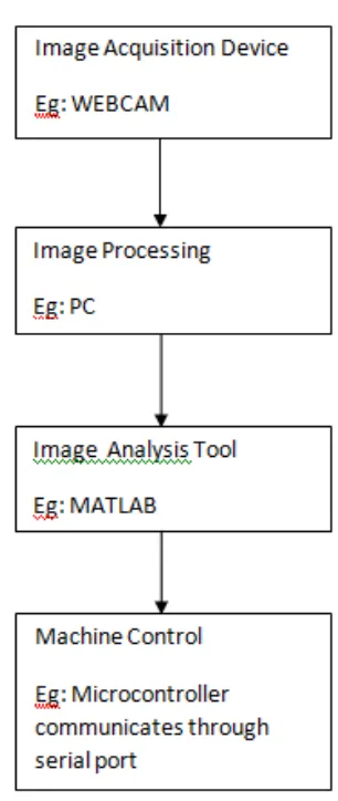
Camera will start to capture the series of eye images and then it is fed to the PC,Here the system uses winvideo interface to interface the camera to the matlab. Using some morphological operations in image processing, the captured RGB image is converted to a binary image. These binary image then undergoes edge detection after this process calculate the centroid of iris images and send it as a serial data to the microcontroller through RF transmitter. The transmitter encodes the data and send as an RF signal. The RF receiver at the wheelchair part receives the signal and decodes it. The RF modem here the system used helps to transmit the data through a serial port. After decoding the processed data is fed to the ATMEGA 328 microcontroller, which produces the corresponding control commands for the motor drivers[4].
[image:4.612.336.489.111.473.2]For detecting static and dynamic objects on the path and their by avoiding collision the wheelchair system uses an Ultrasonic sensor. The sensor which transmit the ultrasonic waves, if any obstacles are in the path the waves are reflected back and then the wheelchair stops[5]. The sensor is connected to the microcontroller.
Figure 2: Flow chart of the system
This is an efficient as well as a cost effective system. Here real time image capturing of eye and iris detection occurs with minimum delay of time.
4) DESIGN METHODS
Following are the types of morphological operations used for our system:
© 2017, IRJET | Impact Factor value: 5.181 | ISO 9001:2008 Certified Journal | Page 251
Binarization is the process of converting a pixel image to a binary image[1].
BW = im2bw(I, level) converts the grayscale image named as I to a binary image. The output image is BW, which replaces all pixels in the input image with luminance greater than a threshold level with the value 1 (white) and replaces all other pixels with the value 0 (black) to specify level in the range [0,1]. This range is relative to the signal levels possible for the image classes. Therefore, a level value of 0.5 is a midway between black and white, regardless of class. For computing the level of argument, use the function graythresh. If you do not specify the level, then im2bw uses the value 0.5 as default. BW = im2bw(X, map, level) converts the indexed image X with colormap to a binary image through maping.
BW = im2bw(RGB, level) converts the truecolor image RGB to a binary image.
If the input image is not a grayscale image, im2bw converts the input image to a grayscale image, and then converts this grayscale image to binary by thresholding.
B) EDGE DETECTION
Edge detection is a morphological operation used for finding the boundaries of objects
within the images[1]. It works
by detecting discontinuities in brightness of each
image pixels. Edge detection is used
for image segmentation and data extraction in image processing, computer vision, and machine vision.
C) EYE TRACKING
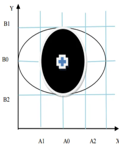
To track the eye movements we uses the coordinate system. Which decide the location of centre point of user’s eye image. Figure 3 indicates the location of the center of iris using coordinate system graph. Where A1 and A2 are the corner points of iris in X direction, B1 and B2 is corner points of iris in Y direction. The X and Y calibration point represents the direction of eye movements[14]. The eyeball position at the (A0, B0) points is:
A0 = (A1+A2) / 2 B0 = (B1+B2) / 2
[image:5.612.329.529.386.632.2]© 2017, IRJET | Impact Factor value: 5.181 | ISO 9001:2008 Certified Journal | Page 252 5) RESULTS
The wheelchair system received the processed data of the captured images. Based on the centroid location, the microcontroller sends the commands to the motor driving circuit. Then wheelchair moves in required direction according to eye movements. An Ultrasonic sensor is used for obstacle detection. It measure the distance between wheelchair and obstacle. When obstacle is very close to wheelchair, motors will stop the wheelchair.
6) ADVANTAGES
The most challenging aspects are finding a good way to differentiate iris and its center locations, determining the eye‘s movement and controlling the wheelchair’s wheels in proper direction. Our system acquires it.
Night vision is possible by mounting infrared cameras.
Ultrasonic sensors detects mobile as well as static obstacles, thus stops the wheelchair.
For getting external assistance, audio options are provided.
7) APPLICATIONS
Neuroscience or Neuropsychology
For vision research
Used in experimental psychology
Used in Cognitive Psychology
For psycholinguistics
Psychiatry specially in Mental Health
Transportation: Flight simulators or Driving simulators
Robotics – Remote Vision Control
Video and arcade games
8) CONCLUSION AND FUTURE WORKS
A) CONCLUSION
Our project, Autonomous Eye consists of a wheelchair, the motion of which is controlled by the eye movements of the user. Autonomous eye is implemented to help physically disabled persons to make their life independent. A sequence of images of the eye will be captured and it is processed in MATLAB to obtain the direction of movement of the wheelchair[10]. There the system used the ultrasonic sensor for obstacle detection[7]. Low cost RF transmitter and receiver are capable of handling some basic wireless communication such as sending basic instruction to MCU of the robotic wheelchair.
B) FUTURE WORKS
© 2017, IRJET | Impact Factor value: 5.181 | ISO 9001:2008 Certified Journal | Page 253 REFERENCES
[1] M.S.Ghute, A.A.Parkhi, K.P.Kamble, Mohsina Anjum, “Iris Movement Detection by Morphological Operations for Robotic Control”, © 2013 IJESIT
[2] Razvan Solea, Adrian Filipescu, Adriana Filipescu Jr, Eugenia Minca, Silviu Filipescu, “Wheelchair Control and Navigation Based on Kinematic Model and Iris Movement”, © 2015 IEEE
[3] Aniket R. Yeole1, Sapana M. Bramhankar2, Monali D. Wani3, Mukesh P. Mahajan4, “Smart Phone Controlled Robot Using ATMEGA328 Microcontroller”, © 2015 IJIRCCE
[4] O. Kov , M. Kovalk, P. Feciľak, F. Jakab, “ Learning module of non-periodic signal digitalization using ATMega328 microcontroller”, © 2015 IEEE
[5] Johann Borensiein , Yoram Korean, ”Obstacle Avoidance with ultrasonic sensors”, © 2014 IEEE
[6] Nischay Gupta, Jaspreet Singh Makkar , Piyush Pandey, “Obstacle Detection and Collision Avoidance using Ultrasonic Sensors for RC Multirotors”, 2015
[7] Sungbok Kim and Hyunbin Kim, “Simple and Complex Obstacle Detection Using an Overlapped Ultrasonic Sensor Ring” , © 2012 International Conference on Control, Automation and Systems
[8] Osama Mazhar, Muhammad Ahmed Khan, Taimoor Ali Shah, Sameed Tehami, ”A Real-time webcam based Eye Ball Tracking System using MATLAB”, © 2015 IEEE
[9] Surashree Kulkarni, Sagar Gala, “A Simple Algorithm for Eye Detection and Cursor Control”, © 2013 International Journal of Computer Technology & Applications
[10] Gunda Gautam, Gunda Sumanth, Karthikeyan K C, Shyam Sundar, D.Venkataraman, ”Eye Movement Based Electronic Wheel Chair For Physically Challenged Persons”, © 2014 International ournal of Scientific & Technology Research
[11] M. Thamrin N.Sarmawi D. S., “Design and Analysis of Wireless Controller Panel using RF Module’s for Robotic Wheelchair”, © 2011 IEEE
[12] Matthew B. Lister; Elizabethtown College; Elizabethtown, PA Joseph T. Wunderlich “Mobile Robot Control over a Radio Frequency Communications Link”, © 2002 IEEE
[13] Himesh Gupta, Aditya Pundir ,Dr.O.P. Sharma, “RF Module Based – Speed Check and Seatbelt Detection System”, © 2016 Second International Conference on Computational Intelligence & Communication Technology