Departm ent of Chemistiy
l i t i Ê î
Study of redox activi^ at modified liquid/liquid interfaces
using electrochemical and physicochemical methods
by:
Dimitra Georganopoulou
A thesis presented to the University of London, in partial fulfilment o f the requirements for the degree of Doctor in Philosophy
All rights reserved
INFORMATION TO ALL USERS
The quality of this reproduction is dependent upon the quality of the copy submitted.
In the unlikely event that the author did not send a complete manuscript and there are missing pages, these will be noted. Also, if material had to be removed,
a note will indicate the deletion.
uest.
ProQuest U643222
Published by ProQuest LLC(2016). Copyright of the Dissertation is held by the Author.
All rights reserved.
This work is protected against unauthorized copying under Title 17, United States Code. Microform Edition © ProQuest LLC.
ProQuest LLC
789 East Eisenhower Parkway P.O. Box 1346
The aim o f this work was to establish an experimental basis for exploration o f the reactivity o f cell membrane-bound redox enzymes, by using electrochemistry at an aqueous/organic interface. The study presented in this thesis consisted o f two parts. The first concerned the effect o f surfactant adsorption on intcrfacial electron transfer. The second involved the measurement of activity of an enzyme within a surfactant-modified interface, catalysing the interfacial electron transfer.
Surfactant adsorption at the interface inhibited electron transfer across an aqueous/ organic interface, between ferro/ferricyanide and dimethyl (DilMFc) or decamethyl (DcMFc) ferrocene, directly in proportion to the fraction o f the surface covered. Interfacial capacitance and interfacial tension measurements gave the surface coverage o f the non-ionic surfactant, sorbitan monostearate, and SECM approach curves gave the overall reaction rate constant. Four-electrode voltammetry revealed an asymmetry of the interface geometry due to surfactant adsorption. Oxidation of the neutral ferrocene was inhibited, but the reduction of ferricenium was not. From the limiting current values for DiMFc oxidation, a model o f uncovered micro-holes was proposed and their diameter within the surfactant layer at nominal full coverage was calculated to be ca. 200 nm.
The adsorption of glucose oxidase (GOx) at the H2O / dichloroethane interface
was also investigated, using capacitance and surface tension techniques. Both methods indicated that the adsorption process was time and concentration dependent. The adsorption isotherm obtained from the double layer capacitance suggested that there are two different adsorption states and that the interface saturated at a bulk GOx concentration of 500 nM. This behaviour was further investigated with specular neutron reflection at the water/air interface, assuming that the behaviour of the enzyme adsorption at the two interfaces is similar. This assumption was strengthened by surface tension results at the water/air interface that indicated similar behaviour to that at the water/oil interface. For low concentrations the neutron data were fitted for a uniform layer o f small thickness and large area/molecule (molecules flattened after adsorption). For higher enzyme concentrations and high ionic strength the area/molecule became comparable with that expected from the dimensions o f the enzyme (molecules retained rigidity). For the even higher concentration range (>400 nM) the fit needed to include a second layer o f flattened molecules, adsorbing underneath the first layer.
The present thesis describes the research carried out mainly at University College London during the years 1999-2001.
First and foremost I would like to greatly acknowledge my supervisor Professor Da^dd E. WiUiams for his continuous encouragement and enthusiasm in this work. I am also greatly indebted to Dr. Jorg Strutwolf for his support and for providing the theoretical simulations to the SECM measurements. I am very grateful to all my “friends and colleagues” in G 16, Dr. Daren Caruana, Camilla Forssten, Hanna Rajantie and Ali Morshed for an enjoyable environment including great discussions, as well as “impression-day Fridays”. I am also very thankful to aU the members o f technical support at UCL, especially to Jim Stevenson, Dick Waymark, Joe Nolan and John Hughes.
I would also like to express my gratitude to Professor Pat Unwin for his guidance, as he and Jie Zhang helped me, while at Warwick, to understand better the SECM and MEMED experiments, as well as to upgrade my SECM set-up back at UCL. Professor Kyosti and Dr. Annu Kontturi, are gratefully acknowledged for their invitation in the Helsinki University o f Technology. Together with the rest o f the group in Finland, especially Drs. Bemie Quinn, Riikka Lahtinen, Christoffer Johans and Peter Liljeroth, provided a very enjoyable environment and helped me grasp the concept of interfacial electron transfer. D r Pereira and Prof. Fernando Silva are also deeply acknowledged for their invitation to Porto University and their input and support with the capacitance measurements. Dr. T.J. SU and Prof. J Lu are acknowledged for their help with the Neutron experiments.
Many thanks are also due to the European network (ODRRELLI), of which UCL was a partner in this project, for supplying the financial support as well as the opportunity to meet, discuss and collaborate with many senior and young researchers in the same field.
Finally and most importantly, I would like to thank all my friends and family and dedicate this thesis to my parents, for all the love, patience and “quantum” support
A B S T R A C T :...1
P R E F A C E :... 2
L IS T O F C O N T E N T S ... 3
L IS T O F C E L L S : ... 7
L IS T O F A B B R E V IA T IO N S :...8
L IS T O F S Y M B O L S :...9
L IS T O F T A B L E S :...9
L IS T O F F I G U R E S :... 10
C H A P T E R 1: IN T R O D U C T IO N T O L IQ U ID /L IQ U ID I N T E R F A C E S ...15
1.1 AIMS AND STRUCTURE OF PROJECT... 16
1.2 His t o r yo fe l e c t r o c h e m is t r ya tl iq u id/l iq u idin t e r f a c e s... 17
1.3 Ge n e r a lc h a r a c t e r is t ic so fth eliq u id/liq u idin t e r f a c e...19
1.4 St r u c t u r eo fl iq u id/l iq u idin t e r f a c e... 22
1.5 Th e r m o d y n a m ic so f IT IE S ...24
1.6 Io n PAIRING AT I T I E S ... 26
1.7 Pa r t it io n in gio n a t n o n-p o i.a r is a r i.f, in tf,r fa c f,s... 27
1.8 Io nt r a n s f e r ( I T ) ... 29
1.8.1 Thermodynamics o f simple ion transfer...29
1.8. a Kinetics o f simple ion transfer...30
1.8. Hi Facilitated ion transfer...31
1.9 El e c t r o nt r a n s f e r ( E T ) ... 32
1.9.1 Characteristics o f electron transfer...32
1.9. a Thermodynamics o f electron transfer...33
1.9. Hi Potential control fo r electron tram fer...35
1.9. iv Kinetics o f electron transfer...37
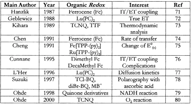
1.9. V Summary o f some experimental investigations on E T....38
1.10 Co u p l in go f E T a n d I T ...42
C H A P T E R 2 :T H E O R E T I C A L B A C K G R O U N D O F V A R IO U S T E C H N IQ U E S ... 43
2.1 Mic r o e l e c t r o d e EXPERIMENTS... 43
2.7 Sp e c u l a r NEUTRON r e f l e c t io nt e c h n iq u e... 53
C H A P T E R 3 : E X P E R IM E N T A L S E T U P ...56
3.1 In t r o d u c t io n... 56
3 .2 Ch e m ic a l s...57
3.2.1 Solvents....57
3.2.a Supporting Electrolytes...57
3.2. Hi Potential Determining Ions and Single Electrolytes....59
3.2. iv Redox couples...6 /
3.2. V Sui^actanls...63
3.2.vi Enzyme...63
3.3 Ex p e r im e n t a l Se t-u p... 64
3.3.1 Preparation o f electrodes...64
3.3.a UV-Vis cell and instrumentation...67
3.3. Hi Surface tension cell and instrumentation...67
3.3. iv Neutron reflection cells and instrumentation...68
3.3.VMicroelectrode cell and instrumentation...69
3.3.vi Aqueous cell and instrumentation...70
3.3. via Four electrode cells and instrumentation...71
3.3. viii MEMED cell and instrumentation...73
3.3.ix SECM cell and instrumentation...74
C H A P T E R 4 ; S U R F A C T A N T A D S O R P T IO N A T A L IQ U ID /L IQ U ID IN T E R F A C E ...79
4.1 In t r o d u c t io n... 79
4.2 Im p e d a n c em e a s u r e m e n t sw it hv a r io u sb a s ee l e c t r o l y t e s...79
4.3 Im p e d a n c estu d yo f SM a d s o r p t io n... 83
4.3. i Facilitated IT in the presence o f SM....S3 4.3. a Measurements in the absence o f facilitated IT ...S4 4.4 Su r f a c et e n s io nd u eto S M a d s o r p t io na tal iq u id/l iq u idin t e r f a c e...86
4.5 D is c u s s io n o n t h e e f f e c t o f s u r f a c t a n t o n Cd a n d y...88
4.6 CONCLUSIONS... 92
C H A P T E R 5 : S T U D Y O F IN T E R F A C IA L E L E C T R O N T R A N S F E R ...93
5.1 In t r o d u c t io n... 93
5.2 MICROELECTRODE MEASUREMENTS...93
5.2. i Aqueous redox species...93
5.2. a Organic redox species...95
5.3 El e c t r o nt r a n s fe rm e a s u r e m e n t sw it haf o u r-e l e c t r o d ec e l l...97
5.4 Dis c u s s io no ne l e c t r o nt r a n s f e ra tap o l a r is a b l ein t e r f a c e... 101
5.5 In TERI'ACIAL ELEC iRON TRANSFER AT A NON-FOLARISABLE IN'lERl^ACE... 104
5.5.1 Interfacial E T with SECM...105
5.5.7/ Inteifacial ET with MEMED... 106
5.6 Dis c u ss io no nin t e r f a c ia l E T a tan o n-p o l a r is a r l ein t e r f a c e... 107
5.7 Co n c l u s io n s... 108
CHAPTER 6; EFFEC T O F ADSORBED SURFACTANTS ON ELECTRO N TR A N SFER 109 6.1 VOLTAMMETRIC STUDIES ON THE EFFECT OF SURFACTANTS IN EITHER PHASE... 109
6. l.i Effect o f surfactants on oxidation o f fF e(C N )af' at Pt...109
6. l.ii Effect o f surfactants on oxidation o f x-Fc at P t...110
6.2. Res u l t sf o re l e c t r o nt r a n s f e rm e a s u r e m e n t sinth ep r e s e n c eo f su r f a c t a n ta tan o n -POLARISABLE INTERFACE...111
6.2. i MEMED studies on effect o f Triton X-100...I l l 6.2. a SECM studies on effect o f sorbitan monostearate...112
6.3 Re su ltsf o re l e c t r o nt r a n s f e rm e a s u r e m e n t sint h ep r e s e n c eo fs u r f a c t a n tw it h FOUR-ELECTRODE VOLTAMMETRY...114
6.3.1 Effect o f Triton X -1 0 0...114
6.3. a Effect o f sorbitan monostearate...116
6.4 Dis c u s s io n... 117
6.5 Co n c l u s io n s... 123
CHAPTER 7 GOX ADSORPTION AT IN T E R F A C E S ...124
7.1 INTRODUCTION... 124
7.2 Im p e d a n c er e s u l t sf o r G Oxa d s o r p t io na tliq u id/l iq u idin t e r f a c e... 126
7.2.1 GOx adsorption with tim e...126
7.2. a GOx adsorption in the presence o f different electrolyte...130
7.3 Su r f a c et e n s io nr e s u l t so f G Oxa d s o r p t io n... 131
7.4 Ne u t r o nr e f l e c t io nf o r G Oxa d s o r p t io na tw a t e r/a iri n t e r f a c e...133
7.4. i Introduction... 133
7.4. i Reflection in null reflecting water (low ionic strength)...134
7.4.7/ Effect o f high ionic strength on GOx adsorption...136
7.4.777 Extent o f immersion o f enzyme layer in water...139
7.5 Dis c u s s io n... 140
7.5.7 Capacitance measurements...140
7.5.77 Surface tension measurements....142
8.1 In t r o d u c t io n...149
8.2 Re s u l t s...149
8.2.i Established protocol fo r enzyme system...149
8.2. a Regeneration o f DiMFc in the absence o f enzyme...150
8.2. Hi DiMFc regeneration by enzyme: Variations o f A(j>....152
S. 2.iv E,ffect o f degassing and surfactants...153
8.2. V Effect o f adsorption method and mediators...154
8.3 Dis c u ss io na n dp r o p o s e dm o d e i... 156
8.4 Co n c l u s io n s...160
CH APTER 9. CONCLUSIONS & FURTHER W O R K ... 162
9.1 Co n c l u s i o n s...162
9. l.i Effect o f adsorption q f S M at licfuid liquid interface...162
9. LU Effect o f GOx adsorption...164
9.1. Hi Inteifacial ET-Effect o f surfactant and GOx adsorption...165
9.2 Fu r t h e rw o r k... 166
REFERENCE L IST... 168
Cell la A g /A g C J
(wro)
0.01 M LiCl 0.001 M BTPPA-Ci
(o)
P t
0.001 M BTPPATPB
(w) P t
0.1 M K H2P O4
0.1 M K2H P O4 Cell lb A g /A g C l
(wro)
0.01 M LiCl 0.001 M BT PPA 'C l
(o)
P t
0.001 M BTPPATPB
(w) P t
0.01 M LiCl
Cell Ic
(wro)
0.01 M TBuACl
(o)
P t
0.01 TBuATPB
(w) P t
0.1 M K H2P O4
0.1 M KJ. IPO4
Aqueous redox species:
Cell 2a: P t
(w)
Redox species Aqueous Electrolyte
R e f
Cell 2b:
(w)
0.00IM N a.Fe (CN),<. 0.01 M NaCl X mM Surfactant
P t(25fim )
Organic redox species:
Cell 3a: A g /A g C l
(wro)
0.01 M LiCl 0.001 M BTPPACl
(") X M x-Fc 0.001 M BTPPATPB
P i (2.‘in m )
Cell 3b: A ff/A e C I
(wro)
0.01 M LiCl 0.01 M DiMFc(o) P t
0.001.MB Cl 0.001 M BTPPA TPB (50 fu n )
X mM Triton x-100
Cell 3c: A ff/A ffC /
(wro)
0.1 M NaClO . 0.01 M DcMFc (") 0.01 M T hexA C lO ,
X mM SM
Pt
(25 fim )
Four-electrode ET:
(wro) (0) (w)
0.01 M LiCl P t P t
Cell 4a: A g /A g C l 0.001 BTPPACl 0.0001 M x-Fc Aq. Redox couple R e f
0.001 BTPPA TPB Aq. Electrolyte
(wro) (0) P t (w)
Cell 4b: A g /A g C J 0.01 M LiCl P t 0.1 M Fe(CN>^ P t
0.00 IM BTPPACl 0.001 M DiMFc 0.01 M Fe(CN)6^ 0.001 BTPPA TPB X M Triton X-100
(wro) ( 0 ) P t P t (w)
0.01 M LiCl 0.001 M DiMFc O.IM K.,Fe(CN)6
Cell 4c: 0.001 M BTPPACl 0.001 BTPPA TPB 0.01 M K4pe(CN)« P t
X M SM 1.5 M IiS 0 4 SECM-MEMED:
(0) (w)
Cell 5a P t
0.001 M DiMFc X M Na4[Fc(CN)£.) 0.1 M T Pr.^T PB 0.01 M TPrACl
ip) ( w )
P t A g /A g C I
Cell 5b: 0.01 M DcMFc 0.00IM a>[Fe(CN)^].10H"O
0.1 M THexACL04 0.25 M N aCL04 0.002M NaHCO?
0.1 M NaCl
X M Triton X-100
(0) (w)
Cell 5c: P t A g (Q R E )
0.01 M DcMFc 0.001 M Na4[Fe(CN)«] 0.1 M ThexA C1 0 4 1 M NaC104
X M SM
Enzyme system:
Cell 6a: A g /A g C l
(wro)
lO m M L iC l 10 mM T(-AIk)ACl
(0)
P t P t
1 mM DiMFc 10 mM T(Alk)AC1 0 4
(w)
0.05 M Glucose,0.2 M K 2 H P O 4
10 mM l (Alk)Cl O4
0.25 mM Triton X-100 560 luM GOX, Cell 6b: A g (Q R E )
(0)
Pt
1 mM DiMFc 30 mM TPrATPB
(w)
550 iiM GOX,
Solvents-Surfactant: 1,2-Dichloroethane
Millipore Q-plus water
Sorbitan monostearate
Aqueous phase
Organic phase
Aqueous reference junction for the organic phase
DCE
H2O
SM (w) (o) (wro) Redox Cotfpks: Ferrocene Dime thylferrocene Decamethylferrocene T etracyanoquinodimethane Fc DiMFc DcMFc TCNQ
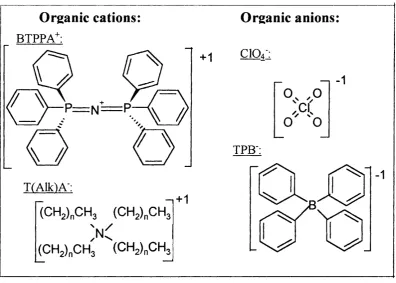
Organic electroljtes-Rotential determining ions: Tetraalkylammonium cation
Perchlorate anion
Bis-triphenyl phosphoranylidene cation
Tetraphenylborate anion
T(Alk)A^
CIO4
BTPPA+
TPB
Techniques:
Scanning Electrochemical microscopy
Microclcctrochcmical measurements at an expanding droplet
Mass spectrometry
Electron ionisation
Fast atom bombardment
Electrospray SECM M EMED MS E l FAB ES Miscalkneous:
Interface between two immiscible electrolyte solutions
Electron transfer
Ion transfer
Potential determining ion
Critical micelle concentration
ac-c° bulk concentration of sp e c ie s Z/ charge of sp e c ies
Cd double layer capacitance, F cm ^ c, concentration of sp ec ies
d distance, m a, activity of sp ecies, M
D diffusion coefficient, cm^ s^ y surface tension, mN m'^
e electron charge, C activity coefficient
E potential, V r surface e x c e ss, mol m ^
standard redox potential, V Galvani potential difference, V
F Faraday constant, C mol ^ AG^’ standard free energy, J
f frequency, Hz & relative permittivity
I ionic activity $ surface coverage
i (I) current, A A wavelength, nm
j com plex number, 0-1 ^ chemical potential, V
k Boltzman constant, J ‘j r electrochemical potential
K equilibrium constant, (M'^) standard chemical potential, V
k rate constant, cm s'^M'^ p ( z ) scattering length density, fm
n number of transferred electrons ov/ Warbourg coefficient, Q s '^
Na Avogadro number, mol^ r layer thickness, A
n, number density z im pedance, ü
Q momentum transfer, A ^ z real impedance, £2
R g as constant, 8.314 J mol’V'^ Z ' imaginary impedance, Q
r radius, m Zir Warburg im pedance, Q
R resistance, Q v scan rate, mV s'^
R X 10-5 Reflectivity ^ Galvani potential, V
Rg microhole radius, m x outer potential, V
Ro radial distance betw een microholes, m ^ surface potential, V S total surface area, m^ to angular frequency, Hz
List of tables:
Table 1.1 Common solvents for liquid/liquid experiments...2 0
Table 1.2 Selection of experimental studies on heterogeneous ET with four-eleclrode technique...38
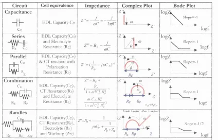
Table 2.1 Standard electrochemical circuits and their characteristics... 51
Table 2.2 Coherent scattering lengths of atoms, 1 fin=10'’^m...54
Table 3.1 Organic electrolytes used and their origin... 58
Table 3.2 Potential determining ions and electrolytes and established potentials... 60
Table 3.3 Redox potentials of aqueous* and organic** species...61
Table 3.4 Measured equilibrium potentials for various ratios in 1.5 M LiS0 4... 62
Scheme 3.1 Chemical structure of the organic electrolyte ions...58
Scheme 3.2 Chemical structure of the non-ionic surfactants, used in the present study...63
Table 4.1: Cells studied with impedance technique...80
Table 5.1 Half wave potential £’2,./„ standard potential and D values for the aqueous redox species, cell 2 ... 94
Table 5.2 Half wave potential standard potential and D values for the organic redox species, cell 3 ... 96
Table 5.3 Predicted and experimental potential values for interfacial ET with various ratios of aq. redox concentrations, using SCE as a reference electrode, £®dîmfc=0.485 V...104
Table 7.1 Structural parameters for the GOx layer adsorbed on the surface of water at 7=0.002M... 135
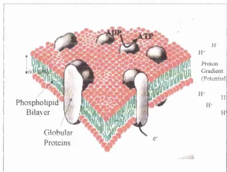
Figure 1.1 Biological membrane indicating the phospholipid bilayer, the integral and peripheral globular proteins, as well as basic steps of the process of oxidative phosphorylation (from ref. 1)...15
Figure 1.2 Electrical Double layer for an electrolyte/electrode solutions, Gouy-Chapman with the diffuse double layer and later modified model indicating the inner Hemholtz plane %i, the outer Hemholtz plane Xi that form the Hemholtz layer a...22
Figure 1.3 Effect of the volume ratio ;=V°/V^ on for partition of counterions of redox species. (Fromreference 111)... 44
Figure 2.1 Theoretical approach curve and a schematic for approach to an unreactive surface... 45 Figure 2.2 Theoretical approach curves for various interfacial normalised rate constants (From botton to top
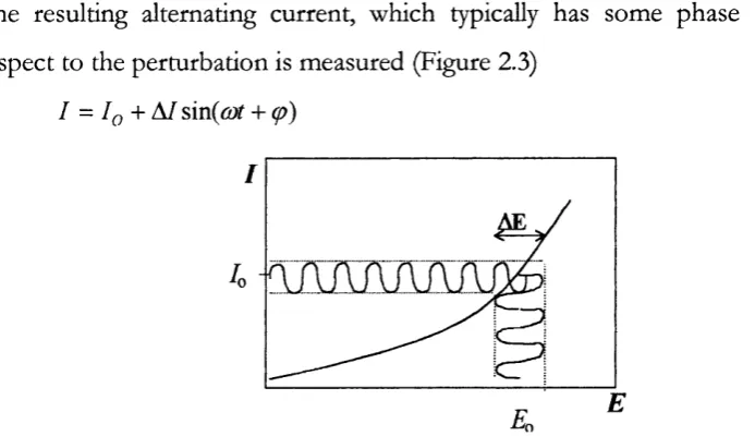
K= 1, 10,25,50,75, 100) and a schematic representing feedback... 46 Figure 2.3 Potential perturbation resulting in an alternating sinusoidal current...48 Figure 2.4 Effect of different cell components on the resulting alternating current (blue line) following an alternating potential perturbation (green line)... 49
Figure 3,1 Nemst equation for the ferrocyanide redox couple for potentials vs SCE (diamonds) and SHE (squares) with their standard potential = 0.48V for alkaline pH...62
Figure 3.2 Reference electrodes, a. Ag/AgCl with reference junction and b. SCE... 65 Figure 3.3 a. Pt “hook” microelectrode (r=25pm) with RG=40, with SEM picture (left) and b. Straight Pt microelectrode (r=25pm) with RG=10, with microscope image photo (right)...6 6
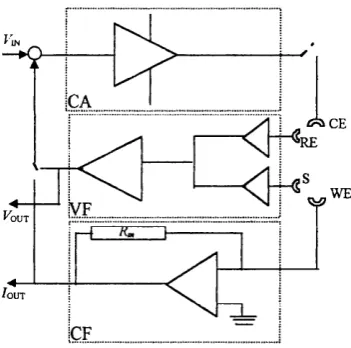
Figure 3.4 Electrochemical cell for microelectrode measurements with organic redox species... 70 Figure 3.5 Four electrode cells a. Porto Univeristy Design b. HUT design... 71 Figure 3.6 Simple schematic of the four-electrode circuit diagram (see text) VF: voltage follower, CF: current follower, CA: current amplifier, R^: measuring resistance...72
Figure 3. 7 Part of the electrochemical cell used in the MEMED experiments with an expanding drop of the organic phase approaching an ultramicroelectrode immersed in the aqueous phase,...73
Figure 3. 8 Part of the electrochemical cell used in the SECM experiments with a ultramicroelectrode
positioned near the interface, with it’s reflection on the other phase... 74 Figure 3.9 The SECM set-up that consists of the video microsopy set-up, the step driver that drives the “hook” microelectrode, the degassing set-up and the current monitoring equipment...75
Figure 3.10 Chronoamperometric measurement as microelectrode approaches the air/DC-E interface. The electrode was held at 0.5 V vs Ag/AgCl (wro), where the cuirent is diffusion controlled for the oxidation of ImM DiMFc in the organic phase with 0.01 M TEACIO4 present and a reference junction of 10m M TEACl, 0.01 M
LiCl / Ag/AgCl. Speed 4.6 pm/sec... 76 Figure 3.11 Normalised approach curve as derived from the transient shown in Figure 3.10. Distance d,
normalised to electrode radius, a, current. I, normalised to current/œ- (Diamonds); experimental data, (solid line).theoretical fit for an insulator’s response...77
Figure 3.12 The SECM electrochemical cell used in Warwick, where the microelectrode was immersed (a.) in the organic phase approaching a flat aqueous phase beneath held below the organic phase due to electrocapillary phenomena, and (b.) immersed in the aqueous phase approaching a concave organic phase at the middle of the interface. The reference electrode was a Ag wire immersed in the respective phase... 77
Figure 4.1 Cyclic voltammograms showing the base potential window for various cells: (blue line 1): cell la, (red line 2): cell lb, (green line 3): cell Ic. Scan rate 25 mVs'^...80
Figure 4. 3 Sets of capacitance values obtained for the three cells of Table 4.1 from fitting the equivalent circuit, shown in the inset, (squares): cell la, (diamonds): cell 1 b and (circles): cell Ic. Solid hnes are fourth order polynomial fits...82
Figure 4.4 Ion transfer induced by increasing SM concentration in Cell la, scan rate 25 mV s '\ (blue line 1): 0.1 mM, (red line 2): 0.5 mM, (black line 3): 1 mM and (green line 4): 5 mM SM...83
Figure 4.5 Set of capacitance curves derived from fitting impedance measurements on cell la to the equivalent circuit of Figure 4.5. From top to bottom: 0,0.05 , 0.1,0.5,1 and 5 mM SM...83
Figure 4.6 Cyclic voltammograms showing the effect on the base potential window (black line 1) of 0.001 M: (red line 2)and 0.005 M: (green line 3)using cell lb. Scan rate 25mV s‘^... 84 Figure 4.7 Complex plane impedance plot for cell lb at E=350 V, with 0.0007 M surfactant present. Points: experimental values, line: fit of the equivalent circuit in the inset with the solution resistance,Co the double layer capacitance, fFc i is the diffusion (Warburg) impedance and i?c r the charge transfer resistance of the base
electrolyte ion transfer processes...85 Figure 4.8 Set of capacitance curves obtained from data as in Figure 4.7 with increasing sorbitan monostearate concentrations using cell lb. From top to bottom 0, 0.2,0.5,0.7,2 and 5 mM... 85
Figure 4.9 Surface tension measurements with cell lb after Ih. of equilibration for the adsorption of the surfactant SM at lire liquid/liquid interface... 86
Figure 4.10 Effect of SM concentrations on the surface excess Tat the liquid/liquid interface calculated from Figure 4.9 and the resulting adsorption isotherm 0-c (see text)... 87
Figure 4.11 Effect of increasing surfactant concentration on capacitance Cd at pzc, using cell la (squares) and cell lb (circles)...88 Figure 4.12 Adsorption isotherm obtained from figure 4.11 using cell la (squares) and cell lb (circles), error bars are the standard deviation from three measurements using cell la, and (solid line): Langmuir fit... 89
Figure 4.13 Langmuirian treatment of the surface coverage values for SM adsorption obtained with
capacitance measurements using cell la : (diamonds), cell lb: (circles): and Langmuir fits (solid lines)... 90 Figure 4.14 Frumkin treatment for coverage values for SM adsorption at the interface with cell lb,
(diamonds): capacitance data, (squares): surface tension data and (lines): Frumkin fit... 91 Figure 5.1 Normahsed cychc voltammogram of ImM K4Ru(CN)ô (1, black line), K4Fe(CN) 6 (2, blue line),
Ru(NH3)oCl2 (3, green line) at a 25 pm Pt microclcctrodc in 0.1 M NaCl, using cell III vs Ag/AgCl. Sweep rates 10
mV/s. Inset : Semilogarithmic analysis... 94 Figure 5.2 Normalised cyclic voltammograms for the oxidation of 0.9 mM Fc(l, black line), 0.25 DiMFc(2, blue line)and ImM DcMFc (3, green line) at a 25 pm Pt microelectrode in 1,2- DC-E, using cell 3. Sweep rates 10 mV/s... 95
Figure 5.3 Semilogarithmic analysis based on the data shown in Figure 5.2... 96 Figure 5.4 Cyclic voltammograms for cell 4a, (black line 1): Base CV in the absence of DcMFc,
(blue line 2): in the presence of Fe°^(CN)fi. Scan rate: 25 mV/s... 98 Figure 5.5 Cyclic voltammograms for cell 4, (a): Base CV in the absence of DcMFc (blue line) and
Ru“^°^(NH) 3 (black line) (b): inteifacial ET for DcMFc. Sweep rates: 10,25,50,100 mV/s... 98
Figure 5.6 Cyclic voltammograms of interfacial ET between O.OOIM DiMFc in 1,2- DC-E, with a reference junction: Ag/AgCl/Q.OOlM BTPPA Cl/ O.OOIM BTPPA TPB and the aqueous Fe°/Fe°^(CN)ô in 1.5M LiS0 4 with Pt
1/1 and (green line 3): 1/10. Sweep rate25mV/s... 100 Figure 5.9 Cyclic voltammograms of interfacial ET between DiMFc, as above and different ratios for the aqueous Fe^/Fe*^(CN)6 as in Figure 5.9 with SCE as a ref. Sweep rate 25mV/s...100
Figure 5.10 Approach curves using cell 5a, with the approach curves (2pm/sec) of a microelectrode (Pt=12.5 mm, RG=10) in organic phase and the aqueous containing from top to bottom: (Solid lines): 0.01,0.007,0.005, 0.002,0.001,0.0007,0 MNa^tFelCN)^], (Dashed lines): tlieoretical curve fits, for top to bottom: k = \\2 ,
9.8,8 4,7,5.6,4,2 cm s'^M'^, insulator...105 Figure 5.11 Current-time transient for the oxidation of [Fe(CN)/‘l at Pt ultramicroelectrode (a=2pm) in the aqueous phase, produced with the interfacial ET using Cell IV, with pH=7.7, as the expanding drop approaches the microelectrode with different flow rates, (blue line 1): 200pl/h, (red line 2):300pl/h, (green line 3): 400pl/h... 106
Figure 6.1 Cyclic voltammogram for the oxidation of ImM Na4Fe(CN)ô using cell 2b (Black line 1): no
surfactant present, (Blue line 2): 0.5mM Triton and (Green line 3): 0.5mM SM. Sweep rates 10 mV/s...109 Figure 6. 2 a. Cyclic voltammogram of 0.0IM DiMFc using cell 3b, (blue line 1): no surfactant, and addition of (green line 2) of 0.2 mM and (black line 3): 0.4mM Triton x-100 b. Cyclic voltammogram of O.OIM DcMFc using cell 3c, (black line 1) no surfactant and addition of (blue hue 2) of 0.2 mM SM. Sweep rates 10 mV/s 110
Figure 6.3 Current-time transients for tlie oxidation of Fe(CN)6‘^ at the microelectrode Pt in the aqueous phase, produced following interfacial ET, using cell 5c, in the absence of surfactant (hne 1) and in the presence of 0.25 mM: (line 2) and 0.50 mM: (line 3) Triton X-100. Flow rate 200 pl/h,...I l l
Figure 6.4 Effect of Triton X-100 on the normalised current Îq?, as in Figure 6.3 for different flow rates, 200pJ/h (squares ), 300pl/h, (diamonds), 400 pJ/h (triangles )... 112
Figure 6.5 Set of SECM approach curves using cell 5d. The experimental curves are shown as solid lines, with surfactant concentrations from top to bottom: 0,0.1 mM, 0.2 mM 0.5 mM, 1 mM, 5 mM. The corresponding theoretical curves are shown in dashed lines (see text)... 113
Figure 6.6 Effect of SM on the bimolccular rate constant obtained from the SECM approach curv'cs in figure 6.4, with increasing surfactant concentration... 113
Figure 6. 7 Cyclic voltammograms of interfacial ET between DiMFc and 0.1 M Na3Fe(CN)g and 0.01 M
Na4Fe(CN)g. (Black line 1): no surfactant present, (Blue line 2): 0.15 mM and (green line 3) 0.35 mM Triton x-100.
...114 Figure 6.8 Effect of the presence of 0.250 mM of surfactant Triton X-100, on the base potential window of Cell 4b in the presence of 0.1 M K]Fe(CN)6 and 0.01 M K4Fe(CN) 6... 115
Figure 6.9 Cyclic voltammograms showing the effect of different SM concentrations on the interfacial ET between 0. ImM DiMFc and the ferro-ferricyanide couple, using cell 4c. From left to right, top: SM= 0.7, 1 mM, and bottom: 2, 5 mM . Sweep rates 10,25, 50, 100, mV/s... 116
Figure 6.10 Treatment of surface coverage obtained from Figure 6.4 at 200 ml h '\ for two different concentration ranges...118
Figure 6.11 Proposed schematic (not in scale) for interfacial ET studied with SECM...120 Figure 6.12 The variation of differential variation (AE^-AE^) of the peak potential differences in the presence and absence of surfactant against different surfactant concentrations. Inset shows the variation of the reduction peak potential, E^, with scan rate at different surfactant concentrations, from top to bottom: 0,0.5,0.7, 1,2 5 mM 120
Figure 6.13 The variation of the peak height, If, of the oxidation peak potential with scan rate, from top to bottom 0,0.05, 0.1, 0.2,0.5,0.7, 1,2, and 5 mM. In the inset the reduction peak height, 4 , at the highest scan rate, corrected for the capacitive current and scaled by the charge Qf passed in the preceding oxidation wave...121
Figure 7.2 Complex plane impedance plot of Z" vs. Z' for^lO-01 Hz, experimental set-up as in cell II, E=360 V, with 400 nM enzyme present. Experimental values are represented as points, solid line is the fit using the equivalent circuit shown in the Equivalent circuit shown in inset...127
Figure 7.3 Capacitance ciu-ves extrapolated from data as in Figure 7.2 with potential, with increasing GOx concentrations, using the four electrode cell (see text). From top to bottom 0, 50,100 150,200, 300,400, 500 nM.
128
Figure 7. 4 Effect of enzyme on the interfacial capacitance at the pzc with cell Ic. Points and solid line: experimental points, Dashed lines: exponential decay for two different states... 128
Figure 7.5 Change of the double layer capacitance with time at E= 350 mV, for two different enzyme concentrations, (line 1): 50 nM, (line 2): 400 nM... 129
Figure 7.6 Effect of GOx on the base potential window ( black line 1), using various enzyme concentrations with eell la: 150 nM (green line 4 ),300 nM(red line 3) 1000 nM (blue line 2)... 130
Figure 7. 7 Effect of enzyme adsorption on the interfacial capacitance at £’pzc=0.35 V with cell la. Circles & diamonds: two sets of experimental data. Dashed lines: Fits for two adsorbed states...130
Figure 7.8 a. Interfacial tension measurements for the study of the adsorption of GOx at the aqueous-organic interface, after 2 hours (diamonds) and 4 hours (squares) of equilibration, b. Plot of ln(c)-c after 4 hours of equilibration... 131
Figure 7.9 a. Plot of y vs c for high ionic strength, after Vi h (diamonds) 2 h (squares) and 14 h(triangles) of equilibration, b. Surface tension Iny-c measurements after 14 hours for equilibration of the adsorption of GOx at the water/air interface, at low ionic strength (dotted line 1) and high ionic strength (solid line 2), see text...132
Figure 7.10 Experimental reflectivity profiles for increasing enzyme concentration in NRW, from bottom to top bulk concentrations: 10,100,400 and 1000 nM of GOx in pH =7. The solid lines represent fits using the uniform layer model (see text). Inset shows the increase in reflection for 100 nM and 0(f=1.5®, after (solid line): Ih and (dashed line) 12h...134
Figure 7.11. a ...136
Figure 7.11. b Experimental reflectivity profiles for increasing enzyme concentration in NRW, in high ionic buffer solution, a. from bottom to top bulk concentrations: 1 0, 1 0 0, 1000,400 nM b. from bottom to top bulk
coneentrations: 10, 100,1000, 2000,6000 nM . The solid hnes represent fits using the uniform layer model (see text)... 137
Figure 7.12 Experimental reflectivity profiles from GOx layers on air/D2 0 interface. Lower curves for 1 pm
GOx bulk concentrations in (Points): 7=0.2 M and (Line): 7=0.002 M and upper curves for 0.01 pm GOx bulk coneentration in (Points): 7=0.002 M and (Line): 7=0.2 M ... 139
Figure 7.13 Apparent surface coverage vs. enzyme concentrations, obtained from capacitance values at the E’pzc,, assuming two states...141
Figure 7.14 Schematic representation of the change of the average surface coverage and conformation of GOx layers at the hydrophilic/hydrophobie interface...146
Figure 8.1 Effect of surfactants (a:Triton X-100, b: SM) on SECM approach curves for cell 6a in the absence
of aqueous redox speeies. The electrode tip was held at +450 mV vs Ag/AgCl in the reference junction, and approach rate is 4.6 pm/sec. (Filled symbols): absence of surfactants and (open symbols): presence of surfactants w ith PO4 only (squares) and Glucose + PO4 (triangles). The solid line represents the theoretical behaviour for an
after equilibration, and (solid line 2) no equilibration. (Dashed line): tlieoretical fit for insulator response 151 Figure 8.3 Normalised SECM current-distance approach curves for cell 6b with similar conditions as in Fig. 8.8, with the different established by various SE: TMAC1 0 4( triangles), TEAC1 0 4(squares), TPrAC1 0 4(circles).
Filled symbols in the absence of glucose and green symbols in tlie presence of glucose with tlie enzyme GOX and the surfactant Triton X-100. The solid lines represents the theoretical behaviour for an insulating substrate (solid line 2) and the feedback response (solid hne 1) with a dimensionless rate constant AT=0.3... 152
Figure 8.4 Effect of degassing in the presence of GOx and absence of surfactant. Normalised SECM approach
curves with conditions as in previous Figure. Circles denote the response for 0.1 M PO4, diamonds show the response with 0.05M Glucose+0 . 1 M PO4 in the aqueous phase after adequate degassing for 30 min and squares
when no degassing of the aqueous phase took place. The solid lines represent the theoretical behaviour for an insulating substrate (l)and K= 0.5 (2)... 153
Figure 8.5 Approach curve after 3h. of equilibration to allow monolayer formation from bulk GOx
concentration of 500 nM with constant degassing, with TPRA^ as a PDI. (line); theoretical fit for an insulator and (diamonds): experimental data for approach speed of 2 pm/s... 154
Figure 8 . 6 Approach curves using cell 6c in the absence of GOx (solid line 1), after spreading 20 pM GOx
(squares & line 2), on the aqueous side and 100 pM UQ (diamonds & line 3), on the organic side of interface. (Dashed line 4): theoretical fit for insulator response... 155
Figure 8. 7 Schematic diagram (not in scale) for the proposed models explored in the present system. Scheme
a. shows an interfacial ET between the organic mediator produced at the tip and scheme b. shows ITof the mediator in the aqueous phase and subsequent homogeneous ET...157
Figure 9. 1 Surface coverage ^vs surfactant concentration c, obtained from the three different methods (see
text). Circles are the experimental values of the capacitance experiments, squares the SECM measurements and diamonds the surface tension measurements, and error bars show the standard deviation. (Solid lines); Langmuir fits and (dashed lines): Frumkin fits... 163
Chapter 1: Introduction to liquid/liquid interfaces
Over the past two decades, the interest in the electrochemistr)' of the interface between two immiscible electrolyte solutions (ITIES) has increased, due to the challenges and numerous applications it presents. The main reason for this interest is that the water/oil interface can be considered as a simple model for half a biological cell membrane. In this respect, the liquid/immiscible liquid interface represents the separation of the aqueous cytosol, i.e. the internal or external cell medium from the apolar central region o f a bilayer membraneb Several aspects of this interface have been investigated, such as the structure, the thermodynamics, as well as the different interfacial charge transfer processes. Based on the need to understand drug delivery and bio-electrolyte equilibrium, studies focused initially on the ion transfer (IT) processes occurring at ITIES. These studies were pursued as the outer membranes of mitochondria for example, were found to be permeable to several ions and polar molecules.
Proton
G radient
( P o te n tia l
I
•ftPhospholipid Bilaver
Globular
Proteins
Figure 1. 1 Biological membrane indicating tlie phospholipid bilayer, tlie integral and peripheral globular proteins, as well as basic steps o f the process o f oxidative phosphorylation (from ref. 1)
ADP to ATP that is the major reaction o f producing energy in the organisms. This aspect o f the inner membranes as well as the electrochemical issues that it raises, led to the idea of modelling and studying the transmembrane electron transfer at the liquid/liquid interface. Such a study of the ITIES is a very intriguing one, posing not only pure scientific challenges, but also providing a helpful insight to significant biological processes, with possible general applications.
1.1 A im s and structure o f project
Guided by the possibility of modelling aspects of bioelectrochemistry, the aims of the present project were the following:
- Study o f adsorption and formation o f layers o f species such as surfactants and enzymes, with electrochemical and non-electrochemical methods.
Thorough study and understanding of the process of electron transfer (ET) across an unmodified (clean) interface that is polarised or not, followed by the study of the effect of adsorbed surfactants
- Adsorption of enzymes at a surfactant modified interface in order to study in ter facial electron transfer via an enzymatic catalytic process, similar to the one observed in biological membranes.
Several techniques were employed during this work. The individual adsorption of the surfactants and enzymes at the interface was studied initially with capacitance as well as surface tension. The interfacial adsorption behaviour o f the enzyme was further clarified using the neutron reflection technique. Since, the main process studied is ET, most o f the techniques used in this study were electrochemical, cyclic voltammetry and chronoamperometry, using macro- and micro-electrodes were two dynamic electrochemical techniques used in order to study the interface under consideration. An adaptation of a three-electrode set-up to a four-electrode set-up, with a counter and a reference electrode in either phase, was mainly employed for the study o f an ideally polarisable interface between the two phases, with no common ions present. I'he scanning electrochemical microscopy (SECM)
technique was used in order to study non-polarisable interfaces that have a common ion in both phases, measuring the feedback current as the micro electrode approaches the interface due to interfacial processes. With this technique also, the effect of surfactants and enzymes on in ter facial ET was studied. Spectroscopic techniques were used to identify reactants synthesised (Mass Spectroscopy), and the result o f possible spontaneous reactions or interfacial transfers between the two phases (UV-Visible). Finally with the aid o f microscopy the status o f the microelectrodes used was controlled.
1.2 H istory o f electrochem istry at liq u id /liq u id interfaces
that introduced the new investigation method for studying the interface using a four-electrode potentiostat with two reference and two counter electrodes^.
'I'he next step was the development of a four-electrode potentiostat, which compensated a large portion o f the applied potential lost in solution resistance,
from Samec and Marecek in the s e v e n t i e s This instrument allowed the kinetic
study o f ITIES and its development was closely followed by the ion transfer
experiments by Koryta in 1 9 7 8^^ These allowed the development o f his theory,
wliich based the polarisability o f ITIES on the standard free energy of ion transfer. This led electrochemists all over the world to study thoroughly the ITIES and its physicochemical and electrochemical properties. 'I’he field o f ion transfer has since been widely studied, with several areas being covered such as facilitated ion transfer, ion transfer across Hpid membranes and bilayers, and phase transfer catalysis.
Over the last two decades, the area o f electron transfer has been the subject of increasing interest. For example Marcus has adjusted his electron transfer theory to apply to liquid/liquid interfaces^^-^^. Novel areas are currently being explored, including metal nanoparticle deposition, photoiduced ET, ET Idnetics with SECM technique, electron transfer across hpid membranes, as well as more comphcated aspects of electron and ion transfer coupling. The current state-of-the-art is summarised in a special issue o f the Journal o f Electroanalytical Chemistry^^. Apart from the numerous papers published on each aspect, several reviews and a number o f books have been pubhshed that have recounted the course of ITIES through
18-19,2021,22 \ brief overview is given over the next few sections o f this Chapter.
1.3 General characteristics o f the liq u id /liq u id interface.
As already mentioned, there are two different types o f interface between the two immiscible liquids studied so far^^:
- The ideally polarisable interface between two immiscible solutions, with a
hydrophobic electrolyte in the organic phase and the hydrophilic electrolyte in the aqueous phase. It can be electrochemically polarised in a wide potential range from an external voltage or current source, and is usually studied with a four-clcctrodc potentiostat.
- The non-polarisable interface exists between two phases with a common ion
(partitioning ion). Since there are few reference electrodes that can be used dircctiy in the organic phase to provide a specific potential difference, it is customary to use a non-polarisable interface to create a reference junction for the organic phase. Alternatively, non-polarisable interfaces can be studied using spectroscopic techniques, or scanning electrochemical microscopy. The potential difference across the interface is determined by the ionic species distributed in both phases.
Immiscibility o f the two solvents is the most important factor in ITIES. The limiting factors determining the choice o f organic solvent for ITIES are: very low solubility in water, low vapour pressure, sufficient polarit)^ and a density
appreciably different from that o f H2O to allow the formation o f a stable interface.
Moreover, a minimum dielectric constant of 10 is required in order to provide dissociation o f many salts within a wide range o f concentrations and to permit sufficient conductivity. The solvents, which meet these criteria and have been widely studied in the ITIES are nitrobenzene and 1,2-dichloroethane (DCE). Although DCE has a considerably lower dielectric constant than nitrobenzene, it exliibits a somewhat wider, more useful polarisation window. It has a relative
permittivity o f £^10.38 and is an aprotic, inert solvent o f type 8 (Bronsted's
classification), immiscible to H2O. Apart from these solvents, in the study of
Table 1.1 Common solvents for liquid/liquid experiments
Solvents R efs Solvents Refs
4-Isopropyl-l -methyl- 2-nitrobenzene
23 Benzonitrile 24
Adipoiiitrile 23 2-fluoro-2 hitrodiphenyl ether 25
Dibutyl carbonate 23 o-Nitro-phenyl-octyl-ether 25
Dioctylcarbonatc 23 o-Nitro-phcnyl-phcnwayl-cthcr 25
Nitrobenzene mixtyres 26 o-Nitrotoluene 27
Dichloromefhane 28 Nitroethane 29
Acetophenone 30 o-Dichlorobenzene 31
Isobutyl-methyl-ketone 32 Propiophenone 33
Chloroform 24 Acetonitrile / Chloroform 34
Extensive information regarding the solvents presented above and their characteristics can be found in “The chemistry o f non-aqueous solvents”, however the main problem with using these solvents, is that the majority of them are toxic^s.
By varying the aqueous electrolyte or its concentration, it is possible to widen the available potential window. Different aqueous electrolyte cations have different transfer potentials from one phase to the other, thus the positive limit o f the potential window can be extended, i.e. K+ will transfer before Li"^. It was demonstrated by KontturP^’^’^ that by increasing the degree o f hydration o f the aqueous anion, in the order of Cl <F <SOp- , the salting out of the organic electrolyte cation TBA+ increases and the negative limit o f the potential window also increases. The same effect of widening the window is observed by increasing the concentration of the aqueous electrolyte.
When a potential difference is applied, ions distribute near the interface so that an excess of charge is present at each side of the interface. An electrical double layer (EDL) at the ITIES is formed by the distribution of ionic and dipolar constituents in the interfacial region. Under certain circumstances and accepting some assumptions, this kind o f phenomenon can be seen as similar to that observed at a metallic electrode/electrolyte solution interface^^. In this case, the existing theories and techniques used to study the latter case can be transposed to the study o f the liquid/liquid interface.
Nevertheless, it should be clarified that the electrical double layer formed at the ITIES is characterised by some specific properties that differ from those o f the metal-electrolyte interface^^. First of all, the boundary between the two immiscible liquids is less well defined than for the metal/electrolyte interface, because the cohesive energy of a metal is much greater than that o f a liquid. In a metal/liquid interface the well-defined boundary between the two phases has an electric charge distributed across the metal surface and the ion free layer (inner layer) formed next to the electrode surface. Up to recently, the molecular structure o f the liquid/liquid interface remained unresolved with many models proposed, including that of a “mixed layer”. Therefore, if the interface consisted o f an extended mixed solvent layer, many physical quantities (e.g. permittivity), would have continuous values across the interface. Alternatively, a diffuse double layer could be present, on both sides o f the interface, with the charge distribution in both phases preserving their diffuse property.
In the following sections of this Chapter a brief description o f some of the main aspects of the ITIES will be described along with some o f the literature of experimental findings and/or theoretical treatments supporting them, including:
• the structure o f the interface • ion pairing at the ITIES
• thermodynamics of ITIES
• non polarisable I'ilE S (partitioning ion)
• ion transfer (IT) of charged species from one phase to the other: thermodynamics/ Idnetics / facilitated IT
• electron transfer (E l) between redox species in respective phases: thermodynamics/ kinetics / various aspects of ET
1.4 Structure o f liq u id /liq u id interface.
There is still not a complete understanding of the interfacial structure between two immiscible solutions, and the microscopic structure of the double layer remains a controversial topic. This issue has given rise to difficulties in the quantitative description of the kinetics of charge processes at the ITIES. This resulted in terms such as “apparent”, “corrected” and “taie” rate constant, since the structure o f the interface determines the distribution of the electrical potential in the interfacial region-^^. The main problem has been the experimental difficulties related to the detailed study of the interfacial liquid/liquid interface.
n®
© © 0
©
9 ©G*
B)
©
-G&
0 ^ ^
4>(sj
4>(nri]
D.L.
:d
/!
Figure 1. 2 Schematic models for the electrical double layer for an electrolyte/electrode solutions, a. Gouy-Chapman-Stem model combining the Hemholtz and Gouy-Chapman models and b. Grahame’s model with the inner Hemlioltz plane and the outer Hemlioltz plane % 2 that
form the Hemholtz layer a, shown here for weak specific adsorption.
d’he analysis of experimental double layer data is still largely based on the classical Gouy-Chapman (GC) theory, proposed for metal/liquid interfaces from the original Hemholtz model (Figure 1.2) by Stern. In this model, applicable only to dilute solutions, ions are considered as point charges and the solvent is simply a dielectric continuum. Grahamc later introduced an inner layer modification, which consisted of oriented solvent dipoles or specifically adsorbed ions. This meant that ions could only approach the metal surface to within their solvated radius without being specifically adsorbed or partially desolvated'^f'^^. In contrast to the rather orderly development of the theory of the EDL at the metal/liquid interface.
development of theory for the liquid/liquid interface involved the proposal of a number o f conceptually different models'^^^ briefly reviewed:
a) Verwey and Niessen^^ gave the first quantitative treatment of the double layer at the ITIES. They represented the liquid/liquid interface as two back to back diffuse double layers, i.e. one phase containing an excess of the positive space charge and the other phase an equal excess of the negative space charge.
b) Boguslavsky et neglected the diffuse double layer and assumed an
ionic bilayer at the ITIES formed by the specifically adsorbed ions on one side o f the interface and by ions of the opposite charge on the other.
c) The model o f two back to back non interacting diffuse double layers was modified by Gavach,^ in order to include an ion free inner layer o f oriented solvent molecules (compact inner layer) sandwiched between them. This modified Verwey-Niessen model (MVN), was supported by Kakiuchi’s electrocapillary experiments'^’^.
d) Girault and Schiffrin'^ presented an alternative model which replaced the inner layer by a “mixed solvent layer” where there was supposed to be a gradual change in the solvent properties. They also promoted the use of the term of “specific adsorption” to describe the interfacial association between ions in the
two respective phases. This idea found support in capacitance results that could
not be explained by the GC theory.
e) Samec^*^ suggested a further modification of the MVN, taking into account ion penetration into the inner region and then later introducing the use of image forces to correct the GC model in the low permittivity organic phase.
g) Cui et later suggested that the MPB theory correlated better theoretical expectations and experimental data for the interfacial capacitance. It was suggested again (as in the MVN theory) that the two phases were separated by an inner layer, into which the ions could not penetrate and whose dielectric constant was different from those in both phases.
h) Schmickler et al}'^ presented a different approach altogether, proposing a
lattice gas model in order to describe the interfacial region, where an extended mixed layer exists with a considerable intermiscibility o f the two phases in the vicinity of the interface.
i) Recently B e n j a m i n ^ ^ presented molecular dynamic calculations that
suggested that the water/dichloroethane interface is very sharply defined but very rough on the molecular scale, manifested by capillaries or fingers o f one liquid protruding into the other. These results closely resemble the capillary wave model. These fingers were found to extend up to 8Â within a few picoseconds, with their length dynamically changing with time. The average over time results in a relatively smooth density profile o f an interface thickness of 8 A.
j) Various experimental surface sensitive techniques are currently being employed in order to resolve interfacial structure, such as surface sensitive spectroscopic techniques (second harmonic generation and sum frequency
generation)55. Strutwolf et al recently presented neutron reflection and scanning
electrochemical microscopy experiments^^, showing that any in ter facial zone was less than 10 A thick. This result correlates well with the molecular dynamics simulations and the capillary wave theory.
1.5 T herm odynam ics o f IT IE S
The state of ions in the two different solvents is characterised by the Gibbs energy
of solvation with solvent molecules orientating around the ionic species. The
Gibbs energy of ion transfer between the two solvents is the difference in the Gibbs energy of solvation in the two solvents. When two immiscible liquids come into contact, there is always a potential difference established across the interface.
The electrical (inner) potential (j), established in each phase can be attributed to;
a) The orientation of the solvent dipoles in the vicinity o f the interface, called the
surface potential x
b) The presence of free ionic charges separated by the interface, which is called the
outer potential ^
^=X+W (1.1)
The magnitude of (j) is determined by the conditions o f the equilibrium established
between the two phases. The potential difference established when two immiscible liquids are brought in contact is given by the separation:
A(j)=Ax+A\i/ (1.2)
with A y /2L?, the outer/Volta potential difference A x the surface potential difference
(concentration dependent) and the Galvani potential difference. At an ideally
polarisable liquid/liquid system there are no common ionic species between the two phases. However in a real system all ions have certain solubility in both aqueous and organic systems. Therefore a more practical definition o f the polarisability in this case is based on the degree o f external control over the
interfacial potential difference - ^(o) > which is the practical
polarisability of the system, with and the inner potential o f the aqueous
and organic phase respectively. The use o f appropriate supporting electrolytes in both phases establishes a potential window where various electrochemical processes can be studied, free from the interference from base electrolyte ionic current. On the other hand, for the non-polarisable I'l'lKS, both phases have a common partitioning ion, which is the one that establishes the interfacial potential
difference Eq. Slight changes of from Eq induce large currents
1.6 I o n p a ir in g at IT I E S
Another diversion from ideal situations appears in the case o f ion pairing across the interface. According to the theory developed by Bjerrum, all oppositely charged ions within a certain distance o f each other are associated in ion pairs. Accordingly, an interfacial ion pair can be formed between two oppositely charged
ions depending on their distance of closest approach. The critical distance d"
needed to enable ion pairing is defined as the point where the electrostatic attraction between the two oppositely charged ions overcomes the thermal energies of the ions:
.2
ZyZr^e
(1.3)
le k T
where ^ are the charges of the ions, e the electron charge, k the Boltzman
constant, £*the solvent relative permittirity, f is the temperature given in Kelvins. Equation 1.3 implies that ion pairing is more likely to happen, the smaller the relative permittivity of the solvent is. The critical distance for each solvent is (fwater =3.57 A and </DCE=27.39 A. As an approximation, all oppositely charged ions within these distances become “undissociated” ion pairs. For greater or equal distances between the ions in each solvent than the critical distances mentioned, there will be no ion pairing. In a similar way, it is possible to observe ion pairing between oppositely charged ions across the interface. Ion pairing occurring between small ions in the aqueous phase (e.g. alkali metal cations,) and the organic
electrolyte ion (e.g. tetraphenylborate, TPB ) has indeed been reported by Cheng et
al^^. They observed that bigger alkali cations were more prone to form ion pairs with TPB' (Cs"^ >Rb+>K+ >Na+ >Li+). They suggested that this was due to the fact that smaller aqueous ions have larger hydration shell that can not penetrate the interfacial region to the same extent as bigger aqueous ions. Conversely, small
organic cations were found to be more likely to form ion pairs. Ferreira et al^'^
argued that this was due to the fact that although small organic ions have smaller radius they can penetrate the interfacial region more easily, as, unlike aqueous ions, they don’t form stable solvation shells.
1.7 P a r titio n in g io n at n o n -p o la r is a b le in te r fa c e s
A non polarisable interface is the interface between two phases, in the presence of
a common partitioning ion The equilibrium condition at constant
temperature and pressure, between these two phases (a) and (b) in contact can be expressed as the equality o f electrochemical potential o f common components /:
. The definition of the electrochemical potential for a charged
common species, is a combination of contributions from the chemical energy and from the electrostatic energy o f the species, given by the following expressions:
]U. = //. + z .F (j) = / / / + R T In + z^F(j> (1.4)
where ^ is the electrical potential,
% is the charge o f the particle u
^ . is the chemical potential of component /,
^ is the standard chemical potential o f component /,
a, is the activity of the component i.
F is the Faraday constant 96485 A s mob^
R is the molar gas constant 8.314 J m oF K \ T is the absolute temperature in Kelvin.
It is not possible to separate the two terms and split the electrochemical potential into a chemical and an electrical term. Based on the condition o f equilibrium given above, the potential difference between the phases, for example the aqueous (w) and the organic (o) can be expressed with:
(1.5)
where ^ ^ is the Galvani potential difference, i.e. the difference in the
inner potential between the aqueous and the organic phase. The definition o f the
chemical potential is substituted in equation (1.5), with the activity replaced by
A r> = j ; ( < , - < , ) + (1.6)
where the constants anci variables have the satne meaning as mentioned above. However the standard Gibbs energy of transfer for an ion / from the organic phase (o) to the aqueous phase (w) is:
) (1.7)
and therefore by combining the two previous equations, a Nernst t)q)e equation is
given for the Galvani potential difference :
+ ^ 1 n (1.8)
which can be rewritten as:
u'r iJ'f
A^ = A^>"+— I n - i - or ^(t> = + — (1.9)
^ ^ zF aj"'> ^ ^ zF c'"' ^ '
with Ay is the standard Galvani potential difference o f a common ion and
Ay the formal potential that takes into account the activity coefficient:
— (1.10)
zF
that varies from medium to medium, as the activity coefficients vary. Standard electrode potentials, JB®, are referenced against the hydrogen electrode assuming
that the energy of reaction H++e Ya Hz is zero. The standard Galvani potential
(difference, A ^ , is related to the Gibbs energy of transfer and (differs from the standard electrode potential in that the former refers to extra thermodynamic assumptions presented here. The most fundamental assumption, is the one proposed by Parker^^, which states that for an organic electrolyte constituted by two sufficiently large hydrophobic ions, e.g. the tetraphenylarsonium+ and the
tetraphenylborate', the two ions have equal standard Gibbs energies of transfer between any pair of solvents. This is based on the fact that both these ions are symmetrical and large with almost the same size and shape, having the charge on the central atom buried under the phenyl groups. Therefore their solvation energy is the same, i.e. their chemical potential is the same.
(O)
1.8 Ion transfer (IT)
Ion transfer is one o f the two faradaic processes that have been extensively studied at ITIES. It has applications in analytical chemistry with particular fields o f interest drug delivery^o and biosensors^h It is a fast process (typically >10"^ cm s*^) and diffusionally controlled so that it is reversible. In the previous section the potential is defined by a partitioning ion, common in both phases that is not part o f the system under study. Conversely, ion transfer is usually studied with a polarisable interface established between two phases, where only one o f them consists o f the
charged species i. The established interfacial potential from the hydrophobic and
hydrophilic electrolyte is such that it prevents the partitioning o f species. In this case, the potential is externally applied to polarise the interface driving the ion to be transferred reversibly from one phase to the other.
1.8.i T h erm od ynam ics o f sim p le io n transfer
The Galvani potential difference for ion transfer is also given by equation (1.8), associated with a single ionic component in one phase, but is not a directly
accessible quantity. Values for and defined in section 1.7 have been
published for several ions based on the extra thermodynamic assumptions, using the Gibbs energy o f partition for components when the two solvents are at
thermodynamic e q u i l i b r i u m ^ ^ . The Gibbs energy of transfer AG^'^''^ refers to the
transfer o f an ion i from a pure solvent (a) to pure solvent (b) (see Appendix I).
The standard potential difference for a transferring ion quantifies the
1.8.Ü K inetics o f sim ple ion transfer
1 he following simple schematic shows a simple ion transfer process, when the aqueous phase is for example positively charged with respect of the organic. This can be achieved if the necessary energy is externally provided to charge the double layer, when finally a potential is reached that corresponds to the Gibbs free energy o f transfer across the interface:
( m
iO)
1—
There have been extensive studies on the kinetics of I T which are listed in a comprehensive review by Samec^^. Kinetic data can be extracted and trusted once the ohmic drop can be reliably compensated for. This can be achieved with the use of improved instrumentation, or the development of micro-interfaces. The IT process is assumed to follow the first order rate law.
1 he ri' kinetics studied with cyclic voltammetr)^ can be described by a Butler- Volmer (B-V) equadon^^ although Kakiuchi*^^ has also formulated a Nernst-Planck
equation (activationless process) that better describes the i-R reladonship for IT
Most models for IT kinedcs assume an activated step, ignoring the interfacial structure. In this case Frumkin t)^pe corrections are applied to the “apparent” kinetic parameters, with the potential drop across the diffuse double layer taken into account.
l.S .iii Facilitated ion transfer
'1‘he standard transfer potential is related to the Gibbs energ)' of solvation in
both phases and can significantly shift in value when specific ionic complexes occur. In the case of facilitated (mediated or assisted) ion transfer, a strongly hydrophobic complexing ligand L, is present in the organic phase, and can selectively combine with a specific ion in the aqueous phase, thus facilitating its transfer across the interface^^. The transfer of some very hydrophilic ions occurs at highly positive potentials that lie outside the obser\^able potential window (established by the electrolytes in each phase). In this case, an ionophore can be used to shift the transfer in a negative direction so that it can be observed, witliin the potential window. It is widely used for two-phase solvent extraction of metal ions.
(w) (0)
1 4 M L
---- IL
The potential for the IT is shifted according to the following equation:
R T
\ ( p = - ^ ( P i - ( ^ ^ ) l n [ ^ % G ^ ] (1 T 4 )
where is the charge of the ion
K ’Ci'i?, the formation constant of the complex
CPl is the concentration of the ligand in the organic phase.
Assuming that the diffusion coefficient of the ligand is the same as that of the
complex, the association constant K can be calculated from the transfer