© 2017 AJAST All rights reserved. www.ajast.net
Performance Measure of Ultra wide Band Antenna for Hexagonal and Rectangular
Shape for Wearable Application
Dr.V.Nandalal
1, A.Pavithra
2, S.Pavithra
3and M.Kalaiselvi
41Professor, Department of Electronics and Communication Engineering, Sri Krishna College of Engineering and Technology, Coimbatore, India. 2UG Scholar, Department of Electronics and Communication Engineering, Sri Krishna College of Engineering and Technology, Coimbatore, India. 3UG Scholar, Department of Electronics and Communication Engineering, Sri Krishna College of Engineering and Technology, Coimbatore, India. 4UG Scholar, Department of Electronics and Communication Engineering, Sri Krishna College of Engineering and Technology, Coimbatore, India.
Article Received: 22 March 2017 Article Accepted: 31 March 2017 Article Published: 03 April 2017
1.INTRODUCTION
Antennas play very important role in the field of wireless communications. Some of them are Parabolic Reflectors, microstrip Antennas, Slot Antennas, and Folded Dipole Antennas. Each type of antenna is good in its own properties and usage. We can say antennas are the backbone for wireless communication without which the world could have not reached at this age of technology. Microstrip patch antennas play a very significant role in today’s world of wireless communication systems. A Microstrip patch antenna is very simple in the construction using a conventional Microstrip fabrication technique.
Rectangular and circular patch antennas are the most commonly used microstrip patch antennas. Dual characteristics, circular polarization, dual frequency operation, frequency agility, broad band width, feed line flexibility, beam scanning and triple band frequencies can be easily obtained from these patch antennas. Micro strip antennas are widely used in the microwave frequency region because of their simplicity and compatibility with printed circuit technology, making them easy to manufacture. Generally a microstrip antenna or a patch antenna consists of a patch of metal on top of the grounded substrate. The substrate is made of a dielectric material.
Various methods are used to feed a micro strip antenna such as inset feed, coaxial feed, aperture coupled or slot coupled feed and proximity coupled feed. Microstrip patch antennas have the important advantage of being low profile and if the substrate is thin enough, they may also be comfortable. Basic structure of microstrip patch antenna, Circular or rectangular microstrip patch has been modified for some applications to other shapes. Hexagonal shape microstrip antenna has smaller size compared to the square and circular microstrip antennas for a given frequency.
The small size is an important requirement for portable communication equipments. Microstrip Line feed is used to feed the antenna. Moreover thick substrate properties are used for improvement of proposed antenna. HFSS software is used to carry out the results. HFSS software is a fully featured software package for electromagnetic analysis and design in the high frequency range.
Recently, there has been increasing interest in wireless body area network (WBAN) systems for a variety of applications such as biomedical, military, and commercial services. Especially in biomedical applications, in order to monitor a patient’s health status, an implanted device needs to collect various physiological data and wirelessly transmit the information to external medical devices in real time.
However, they have a short transmission range due to the low radiation efficiency and the effective radiated power (ERP) regulation of 25 μW. This limitation demonstrates the necessity of a dual-band on-body repeater antenna to deliver weak signals from implanted devices to external devices.
In addition, antenna performance is significantly affected by body tissues due to the high dielectric constant and conductivity at the microwave frequency band. Also, the input impedance and resonance frequency cannot be changed, but the gain and radiation efficiency of an antenna can also be deteriorated when an antenna is operated on or in a body.
In order to be insensitive to the human body effect, compact zeroth-order resonance (ZOR) antennas for implantable and wearable WBAN systems were proposed in. Additionally, to protect the human body from radio wave exposure, the structure of the antennas for WBAN must have a low specific absorption rate (SAR).
A B S T R A C T
In this paper, the Rectangular Patch antenna and Hexagonal Patch antenna are designed to be applied in body area network ,which both operated at 6 GHz (UWB).They can provide different gain. In this paper we give both simulation and the measurement results of the two kinds of antennas. The proposed antenna is fabricated on FR4-eproxy substrate. The parameters of proposed antenna was simulated using HFSS 13.0 software in term of return loss, gain, VSWR, and radiation pattern. The antennas was suitable for WBAN applications such as malignant tumor detection, heart attack and high blood pressure measurement etc.
© 2017 AJAST All rights reserved. www.ajast.net 2. SOFTWARE SIMULATION-HFSS
HFSS is a high-performance full-wave electromagnetic (EM) field simulator for arbitrary 3D volumetric passive device modeling that takes advantage of the familiar Microsoft Windows graphical user interface. It integrates simulation, visualization, solid modeling, and automation in an easy-to-learn environment where solutions to your 3D EM problems are quickly and accurately obtained. Ansoft HFSS employs the Finite Element Method (FEM), adaptive meshing, and brilliant graphics to give you unparalleled performance and insight to all of your 3D EM problems. Ansoft HFSS can be used to calculate parameters such as S Parameters, Resonant Frequency, and Fields.
There are six main steps to creating and solving a proper HFSS simulation. They are:
1. Create model/geometry 2. Assign boundaries 3. Assign excitations 4. Set up the solution 5. Solve
6. Post-process the results
3. FEEDING TECHNIQUE
Microstrip patch antennas can be fed by a variety of methods. These methods can be classified into two categories, contacting and non-contacting. In the contacting method, the RF power is fed directly to the radiating patch using a connecting element such as microstrip line. In the non-contacting scheme, electromagnetic field coupling is done to transfer power between the microstrip line and the radiating patch.
The four most popular feed techniques used are the microstrip line, coxial probe, aperture coupling and proximity coupling. To obtain a desirable return loss at the resonant frequency, a microstrip patch antenna must be matched to the transmission line feeding it. The microstrip line is also a conducting strip. It is easy to fabricate and simple to match by controlling the feed position and rather simple to model. This conducting strip is directly connected to the edge of the microstrip patch.
The conducting strip is smaller in width as compared to the patch and this kind of feed arrangement has the advantage that the feed can be etched on the same substrate to provide a planar structure. This conducting strip and the patch are also made from the same material. However as the substrate
thickness increases surface waves and spurious feed radiation increase, which for practical designs limit the bandwidth (typically 2-5%).This is an easy feeding scheme, since it provides ease of fabrication and simplicity in modeling as well as impedance matching.
Fig.1. Microstrip Line Feeding
4. ANTENNA DESIGN
4.1 Design Calculation
Step 1: Calculation of the Width (W): The width of the Microstrip patch antenna is given by following equation:
Step 2: Calculation of Effective Dielectric Constant (εreff): The following equation gives the effective dielectric constant as
Step 3: Calculation of Effective Length (effL ): The effective length is given as:
Step 4: Calculation of the Length Extension (Δ L): Equation below gives the length extension as:
Step 5: Calculation of Actual Length of Patch (L): The actual length of the antenna can be calculated as:
4.2 Rectangular Patch Antenna
© 2017 AJAST All rights reserved. www.ajast.net characteristics are obtained in the frequency band of interest.
The proposed antenna is designed on low cost FR-4 substrate fed by a 50-Ω microstrip line.
The simulation was performed in High Frequency Structure Simulator Software (HFSS). The antenna parameters such as resonant frequency, return loss, radiation pattern and VSWR are simulated.
A Antenna Structure
Fig.2. Rectangular Microstrip Patch Antenna
B. Parameters of Rectangular Patch Antenna
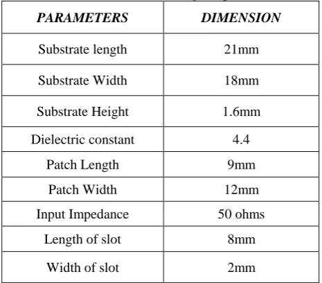
In this section parameters of a rectangular slot antenna has been discussed which is printed on a dielectric substrate of FR4 with relative permittivity (εr) of 4.4. It shows the patch with finite ground plane.
Table 1. Parameters of Rectangular patch Antenna
PARAMETERS DIMENSION
Substrate length 21mm
Substrate Width 18mm
Substrate Height 1.6mm
Dielectric constant 4.4
Patch Length 9mm
Patch Width 12mm
Input Impedance 50 ohms
Length of slot 8mm
Width of slot 2mm
4.3 Hexagonal Patch Antenna
The patch in the antenna is made of a conducting material Copper (Cu) or Gold (Au) and this can be in any shape like rectangular, circular, triangular, elliptical or some other common shape. The hexagonal patch antenna is designed so as it can operate at the resonant frequency. The important parameters for the design of a Hexagonal microstrip patch antenna are frequency of operation, Dielectric constant of substrate and Height of the substrate.
A. Antenna Structure
Fig.3. Hexagonal Patch Antenna
B. Parameters of Hexagonal Patch Antenna
Patch parameters are calculated for the substrate FR-4 with dielectric constant 4.4 by using the above equations. Here we have used h=1.6.
Table 2. Parameters of Hexagonal Patch Antenna
PARAMETERS DIMENSION
Substrate length 13mm
Substrate Width 13mm
Substrate Height 1.6mm
Dielectric constant 4.4
Side of Hexagon 5mm
Input Impedance 50 ohms
Length of slot 5mm
Width of slot 3mm
5. SIMULATION RESULTS
Here the antenna is simulated with two different shape i.e. Rectangular and Hexagonal. The result was simulated using HFSS (High Frequency Software Simulations) and using HFSS antenna parameter like Return loss (S11), Bandwidth (MHz), gain and VSWR (Voltage Standing Wave Ratio) are analyzed.
© 2017 AJAST All rights reserved. www.ajast.net A. Standing Wave Ratio Measurement
It is also measure of mismatch between the load and transmission line. The larger impedance mismatch, the larger the amplitude of the standing wave. It is not more than 2.VSWR was defined as ratio of the maximum voltage to the minimum voltage in standing wave. The VSWR can be represented by VSWR=Vmax/Vmin.
Fig.5. VSWR plot for Hexagonal Patch Antenna
B. Return Loss for Measurement
This may affect the antenna gain to a large extent. The return loss is analyzed using scattering (s) parameters. Return loss is the loss of signal power resulting from the impedance mismatching. An increased return loss leads to a high VSWR. Bandwidth can be determined from the return loss plot or the VSWR.
Fig.6. Return Loss for Rectangular Patch Antenna
Fig.7. Return Loss Plot for Hexagonal Patch Antenna
C. Gain Measurement
Gain is defined as the ratio of the power produced by the antenna from the far field source on the antenna’s beam axis
to the power produced by hypothetical lossless isotropic antenna. Gain was more in microstrip line feeding.
Fig.8. Gain for Rectangular Patch Antenna
Fig.9. Gain for Hexagonal Patch Antenna
D. Radiation Pattern Measurement
Radiation pattern refers to the directional dependence of the strength of radio waves from antenna or other source.
Fig.10. Radiation Pattern for Rectangular Patch Antenna
© 2017 AJAST All rights reserved. www.ajast.net E. Comparison of Antenna Results
Table 3. Comparison of Antenna Results
PARAMETERS RECTANGULAR
ANTENNA
HEXAGONAL ANTENNA
Patch Parameter 4.4 4.4
Return loss(db) -26.6153 -26.9391
VSWR 0.8117 0.7820
Bandwidth 2GHz 2GHz
Gain(db) 5.1218 6.7784
Directivity 7.2180 7.7825
6. CONCLUSION AND FUTURE WORK
Hexagonal and Rectangular micro strip patch antennas with microstrip line feed are designed and simulated using HFSS 13.0, after that performance measures such as return loss, peak gain, VSWR, axial ratio and radiation pattern are observed. The resonant frequency selected for these antennas is 6 GHz. Compare to Rectangular patch antenna, Hexagonal patch antenna has high gain, low return loss and low VSWR. Compare to Rectangular patch antenna, Hexagonal patch antenna smaller in size also. Linear and circular polarizations are obtained by changing the dimensions of a rectangular slot. These antennas are designed for UWB band applications. These antennas are designed only for single band. Dual and triple bands can be carried out in future work.
REFERENCES
[1] P. S. Hall, Y. Hao, and K. Ito, “Guest editorial for the special issue on antennas and propagation on body-centric wireless communications,” IEEE Trans. Antennas Propag., Vol. 57, no. 4, pp. 834–836, Apr. 2009.
[2] Federal Communications Commission (FCC), Revision of Part 15 of the Commission's Rules Regarding Ultra-Wideband Transmission Systems, First Report and Order, FCC 02-48, 2002.
[3] Kim, J. and Y. R. Samii, “Implanted antenna inside a human body: Simulation, designs and characterizations," IEEE Trans. Microwave Theory Tech., Vol. 52, no. 6, pp.1934–1943, Aug. 2004.
[4] C. H. Durney and M. F. Iskander, “Antenna handbook,” Antennas for Medical Applications. New York: Van Nostrand, 1988, Ch. 24.
[5] Sehrish Rashid, S. Ahmad, M. T. Asghar, IrumGillani and N. Kiyani, “Microstrip Patch Antenna for BAN Applications”, International Journal of Engineering Research, Vol.3, No.10, pp 555-558, Oct 2014.
[6] Ramli, N. H., M. R. Kamarudin, N. A. Samsuri, and E. A. Ahyat, “A 6.0 GHz small printed monopole antenna for wireless implantable body area network (WiBAN)
applications," Progress In Electromagnetics Research, Vol. 41, no 10, pp. 189-200, 2013.
[7] K. Y. Yazdandoost and Ryujikohno, “UWB antenna for Wireless Body Area Network”, IEEE proceeding of Asia-Pacific Microwave conference, 2006.
[8] N. Vidal, S. Curto, J. M. Lopez, J. Sieiro and F. M. Ramos, “Detuning study of implantable antennas inside the human body”, PIER, Vol.124, no 5, pp 265-283, 2012.
[9] C. H. Kang, S. J. Wu and J. H. Tarng, “A Novel Folded UWB Antenna for Wireless Body Area Network,” IEEE Trans. On Antenna and Propagation, Vol.60, no.2, pp 189-256, Feb 2012.
[10] K. Itol, N. Chahat, R. Saulean and M. Zhadobov, “A Compact UWB Antenna for On-body Applications”, IEEE Trans. On Antenna and Propagation, Vol.54, No.4, pp 67-99, April 2011.