Comparative Study on the Behaviour of Tubular Structure and Diagrid
Structure Subjected to Dynamic Loading
Avinash S
1Ms. Usha K N
21
PG Student
2Assistant Professor
1,2
Department of Civil Engineering
1,2
EWIT, Bangalore, India
Abstract— The high cost of land and the rapid growths of urban population and to avoid a continuous urban sprawl, and the need to preserve important agricultural production have to contributed to drive residential buildings upward. Diagrid is a particular form of space truss. It consists of perimeter grid made up of a series of triangulated truss system. Study has been carried out for Steel tubular structure provided with 600 angle diagrid. Modelling Study has been carried out for Steel tubular structure provided with 600 angle diagrid. Modelling and analysis is carried out in ETABS using dynamic time history analysis and Bhuj data and analysis is carried out in ETABS using dynamic time history analysis and Bhuj data. Study has been carried out for Steel tubular structure provided with 600 angle diagrid. Modelling and analysis is carried out in ETABS using dynamic time history analysis and Bhuj data. Comparison is carried on tubular steel building and tubular diagrid building with respect to base shear, displacement, drift and time period are found. It was concluded that tubular diagrid structures are economical when storey height is more. The study gives a clear view that diagrid structures are much effective in reducing the response of the structure.
Keywords: Dynamic Loading, ETABS, Tubular Structure
and Diagrid Structure
I. INTRODUCTION
A. General
High-rise buildings with mixed constructions (shear-wall, braced-tube, tube-in-tube) are formed with the combination of several load-bearing structures. The application of particular types of load-bearing systems is determined by the height and geometric form of the building. Due to very complex geometric forms of tall buildings, it has recently been very popular to use the diagrid system for both steel and reinforced concrete. Diagrid is a particular form of space truss. It consists of perimeter grid made up of a series of triangulated truss system.
Diagrid is formed by intersecting the diagonal and horizontal components. Diagrid has good appearance and it is easily recognized. The configuration and efficiency of a diagrid system reduce the number of structural element required on the facade of the buildings, therefore less obstruction to the outside view. The structural efficiency of diagrid system also helps in avoiding interior and corner columns, therefore allowing significant flexibility with the floor plan. Perimeter “diagrid” system saves approximately 20 percent of the structural steel weight when compared to a conventional moment-frame structure.
The diagonal members in diagrid structural systems can carry gravity loads as well as lateral forces due to their triangulated configuration. Diagrid structures are more effective in minimizing shear deformation because they carry lateral shear by axial action of diagonal members. Diagrid
structures generally do not need high shear rigidity cores because lateral shear can be carried by the diagonal members located on the periphery.
B. Diagrid as a Structural System
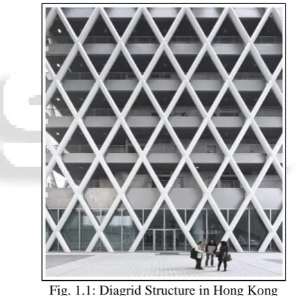
[image:1.595.310.532.327.541.2]Diagrids are the supporting frames which are placed diagonally and made by the connections of different materials like concrete, steel or wooden beams, which are used for the construction of roofs and structures. These diagonal members that are narrow which help in resisting both in gravity and in lateral loads. Diagrid buildings with steel members are very well-organized in providing solution for both strength and stiffness. Diagrid buildings with steel members are very well-organized in providing solution for both strength and stiffness.
Fig. 1.1: Diagrid Structure in Hong Kong
C. Properties of Diagrid Buildings
A diagonal in diagrid buildings understand the moments and shears, not only the lateral load, but also due to the vertical loads. The optimum angle is 35º that is taken for braced building which is composed of straight up columns and of diagonals. Also the equivalent optimum angle in the region 90º is assumed for the frame in which axial forces are carried by the columns.
Fig. 1.3: Diagrid structure with Varying Angle
II. OBJECTIVES
Understand the behavior of angled diagrid in comparison with tubular steel structure.
Study has been carried out for Steel tubular structure and Steel tubular structure provided with 60º angle diagrid.
Modelling and analysis are carried out in ETABS with high seismic zone and dynamic time history analysis.
Efficiency of tubular steel buildings with respect to base shear, displacement, drift are found out for the respective geometric configurations.
The behaviour of the building on implementation of diagrids to tubular buildings will be summarized based on the obtained results.
III. METHODOLOGY
E-tabs is used for modelling and analysis of buildings.
Desirable steel sections are used for modelling.
Two models with steel moment resisting frames will be considered and analysis is done for tubular steel structures with diagrids and structures without diagrids.
Time history method is used for analyzing and the response Quantities like displacements, base shear, drift and time period are noted.
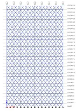
To study the behavior of diagrid buildings, a building with G+30 storeys is been modelled. The diagrid steel structure with the diagrid angle being 60º and conventional steel structure is examined. The modelling and analysis is carried out using ETABS with Bhuj Time history data.
[image:2.595.57.273.62.189.2]Fig. 3.1: 2D Elevation of Tubular Diagrid Structure with 60º Angle
Fig. 3.2: 3D Elevation of Tubular Diagrid Structure with 60º Angle
Fig. 3.3: 2D Elevation of Tubular Steel Structure
Fig. 3.4: 3D Elevation of Tubular Steel Structure
A. Description of Analytical Model
No of storeys G+30
Building type Tubular steel section
[image:2.595.98.231.551.740.2]Typical Storey Height 3m
Seismic Zone Zone V
Soil Type Type 2
Response Reduction Factor 5
[image:3.595.298.531.54.538.2]Importance Factor 1
Table 3.1: General details of the buildings
Thickness of Deck 0.2m
Beam ISMB
Column ISWB
Wall Thickness Glazing load is considered Table 3.2: Structural members of the buildings
Grade of concrete M30
Grade of Steel Fe350
Density of Concrete 25 kN/m3
Young’s modulus of concrete 27386x10³kN/m²
[image:3.595.58.277.63.313.2]Poisson’s ratio 0.2
Table 3.3: Material properties of the buildings Slab live load 4kN/m²
Floor finish 1.5kN/m² Glazing load 1kN/m² Table 3.4: Assumed load intensities
IV. RESULTS AND DISCUSSION
Comparative study on the behavior of tubular structure and diagrid structure subjected to dynamic loading is carried out for the Base shear, Storey displacement, Storey stiffness, Storey stiffness, Storey Drift, Time period.
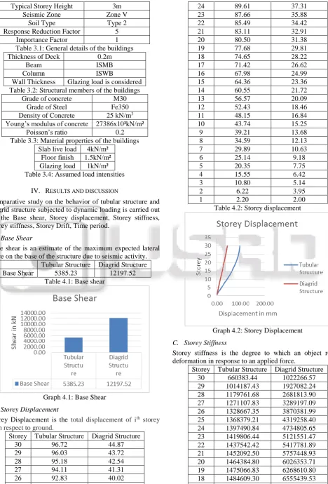
A. Base Shear
Base shear is an estimate of the maximum expected lateral force on the base of the structure due to seismic activity.
Tubular Structure Diagrid Structure
Base Shear 5385.23 12197.52
Table 4.1: Base shear
Graph 4.1: Base Shear
B. Storey Displacement
Storey Displacement is the total displacement of ith storey
with respect to ground.
Storey Tubular Structure Diagrid Structure
30 96.72 44.87
29 96.03 43.72
28 95.18 42.54
27 94.11 41.31
26 92.83 40.02
25 91.33 38.69
24 89.61 37.31
23 87.66 35.88
22 85.49 34.42
21 83.11 32.91
20 80.50 31.38
19 77.68 29.81
18 74.65 28.22
17 71.42 26.62
16 67.98 24.99
15 64.36 23.36
14 60.55 21.72
13 56.57 20.09
12 52.43 18.46
11 48.15 16.84
10 43.74 15.25
9 39.21 13.68
8 34.59 12.13
7 29.89 10.63
6 25.14 9.18
5 20.35 7.75
4 15.55 6.42
3 10.80 5.14
2 6.22 3.95
1 2.20 2.00
Table 4.2: Storey displacement
Graph 4.2: Storey Displacement
C. Storey Stiffness
Storey stiffness is the degree to which an object resists deformation in response to an applied force.
Storey Tubular Structure Diagrid Structure
30 660383.44 1022266.57
29 1014187.43 1927082.24
28 1179761.68 2681813.90
27 1271107.83 3289197.09
26 1328667.35 3870381.99
25 1368379.21 4319258.40
24 1397490.84 4734805.65
23 1419806.44 5121551.47
22 1437542.42 5417781.89
21 1452092.50 5757448.93
20 1464384.80 6026353.71
19 1475066.83 6268610.80
18 1484609.30 6555439.53
[image:3.595.60.529.65.756.2]16 1501622.70 7020043.87
15 1509602.69 7280526.46
14 1517504.57 7525232.82
13 1525505.30 7781363.11
12 1533772.70 8052089.64
11 1542475.18 8406765.07
10 1551792.83 8693335.09
9 1561934.78 9012111.39
8 1573176.83 9556060.49
7 1585965.77 9979129.39
6 1601249.79 10437649.00
5 1621602.45 11300597.00
4 1655241.20 12123228.00
3 1731850.36 13107631.00
2 1982037.65 14055442.00
1 3637682.14 11028239.00
Table 4.3: Storey Stiffness
Graph 4.3: Storey Stiffness
D. Storey Drift
Storey Drift is defined as ratio of displacement of two consecutive floors to height of that floor.
Storey Tubular Structure Diagrid Structure
30 0.00023 0.000404
29 0.000288 0.000417
28 0.000358 0.000433
27 0.000432 0.000454
26 0.000506 0.000465
25 0.00058 0.000484
24 0.000654 0.000498
23 0.000726 0.00051
22 0.000799 0.000526
21 0.00087 0.000533
20 0.000941 0.000544
19 0.001011 0.000553
18 0.001079 0.000557
17 0.001145 0.000563
16 0.001209 0.000566
15 0.001269 0.000566
14 0.001326 0.000567
13 0.001379 0.000564
12 0.001428 0.000561
11 0.001471 0.000551
10 0.001509 0.000545
9 0.001541 0.000538
8 0.001566 0.000518
7 0.001586 0.000507
6 0.001597 0.000494
5 0.001599 0.000465
4 0.001584 0.000443
3 0.001526 0.000417
2 0.00134 0.000402
1 0.000732 0.000934
Table 4.4: Storey Drift
Graph 4.4: Storey Drift
E. Storey Bending Moment
A bending moment is the reaction induced in a structural element when an external force or moment is applied to the element causing the element to bend.
Storey Tubular Structure Diagrid Structure
30 1139.5572 2996.6144
29 3447.0617 9008.1832
28 6905.0675 17961.1318
27 11492.9856 29780.8131
26 17188.7923 44389.2373
25 23970.9461 61704.0849
24 31819.7778 81636.6865
23 40718.4414 104091.2292
22 50653.0031 128965.8031
21 61611.9756 156150.7279
20 73584.9898 185532.6463
19 86561.0926 216994.7941
18 100526.4132 250418.9524
17 115462.5109 285688.7305
16 131345.4171 322692.2229
15 148145.3302 361322.1042
14 165826.4425 401477.5685
13 184346.1047 443065.4935
12 203653.425 485996.066
11 223688.6239 530183.8503
10 244383.0188 575544.7333
9 265660.5731 621992.7363
8 287440.2542 669434.736
7 309639.3773 717773.2721
6 332176.9946 766900.2533
5 354976.5348 816695.4414
3 401086.9223 917779.119
2 424278.1129 968790.4367
1 447494.2814 1019930
Table 4.5: Storey Bending Moment
Graph 4.5: Storey Bending Moment
F. Time Period
A system is said to be vibrating in a normal mode when all its masses attain maximum values of displacements and rotations simultaneously, and pass through equilibrium positions simultaneously.
Mode Tubular Structure Diagrid Structure
1 3.448 1.551
2 3.393 1.488
3 2.226 0.654
4 1.134 0.454
5 1.114 0.433
6 0.74 0.239
7 0.658 0.225
8 0.645 0.215
9 0.461 0.163
10 0.451 0.157
11 0.441 0.153
12 0.35 0.147
Table 4.6: Time Period
Graph 4.6: Time Period
V. CONCLUSION
In this study a structural model with tubular structure and tubular structure with diagrid of 60º angles is considered as the building models, where in these models are analyzed using Time history method and the data corresponding to
Bhuj data are considered, their corresponding behaviors and results are extracted and interpreted. Various parameters such as displacements, storey drifts, storey acceleration, storey force, storey Stiffness, base shear, time period and storey bending moment have been grouped. Hence from the obtained results the following conclusions are made. 1) Storey Displacement was found less in diagrid structure
than that in structure without diagrid system.
2) The angled diagrids provided proper stiffness to structure that intern result in decreasing the storey displacement. 3) Tubular diagrid structure with 60º gives lesser storey
shear and less storey drift than that for conventional tubular structure.
4) In terms of utilization of steel and concrete, the angled diagrid structure is found to be more economical. 5) The base shear for the diagrid model is found to be more
than the tubular steel structure, which imply higher stiffness to the structure that interns offer higher resistance against overturning, higher stability and assure safety to the occupants.
6) Also, tubular diagrid structures are economical when storey height is more.
7) The comparative study on tubular steel structure and tubular diagrid steel structure with 60º give a clear view that diagrid structures are much effective in reducing the response of the structure and is compatible.
REFERENCES
[1] Khalid K Shadhan,”Optimal Diagrid Angle to Minimize Drift in High-Rise Steel Buildings Subjected to Wind Loads”.
[2] Jatin B Tank, Ashwin G Hansora,”Analysis of Varying Angle Diagrid Structural System for High-Rise Steel Building”.
[3] Kyoung Sun Moon, “Sustainable Design of Diagrid Structural Systems for Tall Buildings”, International Journal of Sustainable Building Technology and Urban Development / March 2011.
[4] Nishith B. Panchal, Dr. V. R. Patel, Dr. I. I. Pandya, “Optimum Angle of Diagrid Structural System”, International Journal of Engineering and Technical Research (IJETR) ISSN: 2321-0869, Volume-2, Issue-6, June 2014.
[5] Deepa Varkey, Manju George, “Dynamic Analysis Of Diagrid System With Complex Shape”, IJISET - International Journal of Innovative Science, Engineering & Technology, Vol. 3 Issue 8, August 2016.
[6] Sree Harsha J, K Raghu, G Narayana, “Analysis of Tall Building for Desired Angle of Diagrids”, International Journal of Research in Engineering and Technology. [7] Saket Yadav, Dr. Vivek Garg, “Advantage of Steel
Diagrid Building Over Conventional Building”, International Journal of Civil and Structural Engineering Research Vol. 3, Issue 1, pp: (394-406), Month: April 2015 - September 2015.
[9] Deepika R, Shivanand C.G, Dr. Amarnath K,” Performance Study of High Rise Buildings with Diagrid and Hexagrid Systems under Dynamic Loading”, Volume 6 Issue No. 4.