NEW DIGITAL ANGLE MEASUREMENT FACILITY BASED
ON FPGA
1
HAO ZHAO,2 HAO FENG
1
Jiaxing University, Jiaxing Zhejiang China
2
Hangzhou Dianzi University, Hangzhou Zhejiang China E-mail: [email protected]
ABSTRACT
A new structure angle measurement facility is presented, the principle of facility is linear interpolation subdivided to electric grating with high-frequency pulses, the mechanical structure of measurement facility is simplified, and avoiding the difficulty of subdivision angle on physical condition while compared with the ordinary high accuracy angle sensor. The signal processing of facility based on Filed Programmable Gate Array and single-chip microprocessor realized non-contacted angle measurement. The error of facility is analyzed and tested by experiments; the high theoretical accuracy of measurement facility is verified according to the test, so this system is promising.
Keywords: Angle; FPGA; High-Frequency Pulse; USM
1. INTRODUCTION
In order to get the information of angle, sensors are used either in the static angle measurement or dynamic, the angle signal are turned into circuit parameters firstly, and then converted into electricity output through the conversion circuit, and the value of angle is received through the processing of output signal. Angle and angular displacement sensor are applied in instrument measurement widely, such as industrial automation, signal detection, aviation and navigation, and other fields [1].
In recent years, some experts implement lots of research on angle measurement and obtained a series of achievements. A non-contact capacitive angle sensor is introduced by Wang Jia-xin, the sensor is based on a passive rotating electrode placed between two mechanically static and electrically active electrodes, the main advantage of this sensor cost low [2]. YE discussed an area-alterable differential capacitive sensor, which can measure both displacement and angle, the angle measurement range is from 0~180, the accuracy is 0.5[3]. A design scheme measuring little angle with linear CCD is presented by WANG Y, The auto-collimated measurement scheme can prove accuracy effectively and complexity programmable logic device (CPLD) is used to drive and detect the CCD signal [4]. According to the mechanisms of
high-frequency pulse, thus the mechanical structure and difficulty are simplified greatly, compared with the current widespread high precision angle sensor, it avoids the difficult of subdivision grating on mechanical and physical condition, and left a large space to improve the accuracy in theory, so it has good application prospects.
2. MEASURING PRINCIPLE OF SYSTEM
The structure schematic of angle sensor is shown in figure 1. The figure shows that the core components of sensor include a grating turntable which has a scribed line, static photoelectric sensor which is fixed on the sensor base and a dynamic photoelectric sensor, which include a pair of photoelectric sensors that is located in the two sides of the turntable external, and connected with the input angle shaft. The motor with a constant speed
0
n
drive the grating turntable, when the grating turntable scribed line through static photoelectric sensor, static sensor reflective photoelectric sensor output pulse signal. When the grating turntable scribed line pass through dynamic photoelectric sensor, dynamic photoelectric sensor output pulse signal too. Static and dynamic sensors output pulses signal with the grating turntable rotating continuously, the phase difference of output pulse between static and dynamic sensors is the angle
θ
between two sensors.Figure1 Angle Sensor Structure Schematic
When the grating turntable do counterclockwise rotating continuously, static and dynamic sensors generates two pulses, after filtering, amplify and plastic two signals, they are converted into DATA1 and DATA2 which are shown in figure 2. The phase difference of two pulses is the angle between static and dynamic sensors. In order to measure this
JDMK through electronic circuits, which is the phase difference of pulse signal DATA2 and DATA1. The signal JDMK begins with the rise edge of DATA1 and ends with the rise edge of DATA2, and obtain square wave signal YZMK which is the width of DATA1 pulse cycle. The rise edge of the signal DATA1 is the effective signal for YZMK. Then use high-frequency pulse signal CLK to do and logic with two square wave signals JDMK and YZMK, we can get signal ANGLE and signal CYCLE respectively. Last, count the number of high-frequency pulses in a pulse width of ANGLE and CYCLE respectively, and signal DONE1 and DONE are counter end counting signal, if count results are
N
0 andN
1 , soθ
=
N
0N
1×
360
.3. SYSTEM REALIZATION
In order to realize the measurement method, the system includes three parts: angle generation module, waveform conversion module and digital signal processing module (FPGA).
Angle signal generation module: the core components of this module are transmission photoelectric sensor ST120 and reflecting photoelectric sensor ST188. The circuit of this module is shown in fig 3, one part is the launch circuit, which is composed mainly by infrared emission diode, resistorR1to restrict flow and the adjustable resistorR2, the other part is receiving circuit, it is mainly composed by infrared receiving transistor and resistor
R
3.Figure2 Timing Diagram Of Principle
Figure4 Signal Waveform Conversion
Waveform conversion module: signal
processed in FPGA should be a square wave signal, so the angle signal generated from photoelectric receiving pipe should be converted into square wave signal. The signal waveform conversion circuit is shown in figure 4, put two signals pass through operational amplification, the amplification
coefficient is
R
5R
6 . Then two signals put into ahigh precision voltage comparator LM339, last we
can obtained two corresponding converted square wave signals. In order to match the voltage of FPGA chip I / O port, the pull-up voltage is 3.3V.
Digital signal processing module (FPGA): in
order to obtain count number
N
0 andN
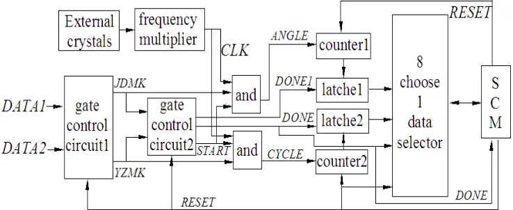
1 , the [image:3.612.122.491.543.694.2]digital signal processing circuit is as shown in figure 5 according to the principle of measurement facility.
In figure 5: DATA1 is generated from static sensor; DATA2 is generated from dynamic sensor;
JDMK is the phase difference of DATA2 and DATA1; YZMK is the width of DATA1 pulse cycle; Counters reset and two gate control circuits initialization signal is
RESET
; Signal JDMK and YZMK implement and logic with signal CLK , then received signal ANGLE and CYCLE; Counters begin to count signalSTART
; Counters end to count signal, Latches latch count value, opening eight choose one data selector and informing SCM count over signal isDONE
. The working processes of the circuit are as follow:SCM initializes signal RESET as logic '1', internal counter of FPGA begin reset and gate control circuit start initialization, signal START is logic '0', signal DONE1 and DONE is logic '1' .
SCM control signal RESET changed as logic '0', then gate control circuit1 begin working, signals JDMK and YZMK are received.
When the signal JDMK first rise edge arriving, signal START changed as logic '1', two and gates open, signals ANGLE and CYCLE are received.
The signal START flips as logic '1' when the rising edge of first JDMK signal coming, internal counters FPGA start to count the number of pulses in a width of signal ANGLE and the number of pulses in a CYCLE. The signal DONE flips as logic '0' when the rising edge of second YZMK signal coming, internal counters of FPGA end count and the count value exists in latches, the data selector is opened and informing the SCM that can reads the count results.
The I/O mouth of SCM is 8 bits, the internal two counters of FPGA are 32 bits, the count value is read into memory of SCM through eight choose one data selector, single chip microcomputer carries on the data processing .
Simulation for the circuit, the results are as shown in figure 2. Predictably, the designation of circuit is able to perform a complete required function of measurement facility.
4. EXPERIMENT RESULTS
Experiments are tested in order to verify the feasibility of the measurement facility. The type of FGPA is EP2C8Q208; the high frequency pulse is 100MHz; the type of SCM is AT89S52, and its clock frequency is 12MHz.
In order to test signal processing part error of measurement facility, experiment 1 uses another piece of FPGA and active crystal generates a pulse signal as reference signal, counting the number of high frequency pulses within a cycle and two cycle respectively at the same time; in experiment 2, actual motor drive sensor that generates pulse signal as reference signal, counting the number of high frequency pulses within a cycle and two cycle respectively at the same time too.
Experiment 1: The other piece of FPGA (EP2C5T144C8) and active crystal generates a reference pulse signal. The high precision pulse signal frequency is about 10HZ, counting the number of high frequency pulses within a cycle and two cycles respectively at the same time. The experimental results are shown in table 1:
Table.1 Experiment 1 Results
0
N 99999931 99999930 99999931 99999932 99999930 99999931
1
N 199999860 199999861 199999862 199999863 199999863 199999863
θ
180 179.999 180 180 179.999 179.999From the result of experiment 1, we know that: The accuracy of reference signal generated by another FPGA and high-frequency crystal is very high, the count errors of pulses in a cycle is produced in the period of counter counts start and end.
When the accuracy of reference pulse signal is guaranteed, the measuring accuracy of the facility is very high. It proves that using high frequency pulse interpolating subdivision electrical grating, the
Experiment 2: The actual motor drive sensor generates a reference pulse signal. from the experiment 1 we know that, if the reference pulse itself has very high precision, then the system will be able to achieve very high accuracy, precision of angle measurement is mainly dependent on the reference pulse precision, it is to say the motor rotation per revolution within the uniform accuracy, the speed more uniform, the higher accuracy it is.
company SHINSEI that drives the sensor grating turntable, high frequency pulses is 100MHZ, counting the number of high frequency pulses
within a cycle and two cycle respectively at the same time. The experimental results are shown in table 2:
Table.2 Experiment 2 Results
0
N 79992750 80519286 81270944 81927892 82335127 82756411
1
N 160020002 161077228 162691374 163899854 164683478 165578325
θ
179.961 179.956 179.843 179.952 179.985 179.928It is known from table 2 that, the speed of ultrasonic motor has low motility on the condition of opening loop operation, the longer, the speed is lower. This is because the friction between the ultrasonic motor stator and rotor, the heat produced by friction can make motor temperature rise, resulting in speed declined slowly, so the next lap high-frequency interpolation pulse number is increased, so result is always less than 180 degrees, the motor speed error becomes the system measurement main error.
5. CONCLUSION
This paper proposes a new principle of angle measuring facility and introduces the designation, the facility error is analyzed through experiments. The facility has the advantages of simple structure, because of the electric pulse interpolation principle, this facility can achieve very high precision on theoretically analysis, but for the current electromagnetic drive motor have obvious vibration torque, it brings influences to the uniform of the drive motor, there exists low speed creeping in ultrasonic motor when in open loop operation, they have become the main error sources of measuring facility, so, how to realize a low vibration torque of the electromagnetic motor and overcome low-speed creeping of the ultrasonic motor become the key of angle measurement facility in practical application.
ACKNOWLEDGMENT
This study was supported by Jiaxing Science and Technology Research Project (number is 2012AY1021) and Zhejiang Provincial Department of Education Scientific Research Project (number is Y201226082).
REFERENCES
[1] ZHANG K, YANG QH, LI B. Based on Hall Competent Non-Contacted Angle Sensor, 2008, 21(6):981-984. In Chinese.
[2] WANG JX, LI XSH. Robust Capacitive Angular Sensor , 2007(6): 3-5. In Chinese. [3] YE YB, LIU ZHCH. Design of capacitive
sensor for both displacement and angle measurement, 2004, 23(3): 34-37. In Chinese. [4] WANG Y, ZHANG ZH B, TANG SH W.
Design of New type angle sensor, 2005, 24(1): 45-47. In Chinese.
[5] ZHANG Q, ZHAO K CH, CHU J K. Design and implementation of bionic angular measurement sensor based on embedded system, 2008, 27(9): 106-108. In Chinese. [6] ZHAO H, ZOU J B, LI T C. A Novel Angle
Measuring Method in Resolver Model, 2002(3): 68-69. In Chinese.
[7] QIAN J Q, HUI M, WANG D SH. Research of Dual Axis Small Angle Measurement Based-on Hugh sensitivity Quadrant Detectors , 2002,
23(2): 538-539. In Chinese.
[8] LI H Q, CHEN Q, WANG Y. A New digital Subdividing Technique for Grating Signal and Its Error Analysis, 2001, 22(4): 281-283. In Chinese.
[9] WANG Q D, YU J CH, ZHONG ZH Y. Application of Phase Shift Interferometry to the Measurement of Small Angle and Linearity,