R E S E A R C H
Open Access
Detection of shifted double JPEG compression by
an adaptive DCT coefficient model
Shi-Lin Wang
1*, Alan Wee-Chung Liew
2, Sheng-Hong Li
3, Yu-Jin Zhang
3and Jian-Hua Li
1Abstract
In many JPEG image splicing forgeries, the tampered image patch has been JPEG-compressed twice with different block alignments. Such phenomenon in JPEG image forgeries is called the shifted double JPEG (SDJPEG) compression effect. Detection of SDJPEG-compressed patches could help in detecting and locating the tampered region. However, the current SDJPEG detection methods do not provide satisfactory results especially when the tampered region is small. In this paper, we propose a new SDJPEG detection method based on an adaptive discrete cosine transform (DCT) coefficient model. DCT coefficient distributions for SDJPEG and non-SDJPEG patches have been analyzed and a discriminative feature has been proposed to perform the two-class classification. An adaptive approach is employed to select the most discriminative DCT modes for SDJPEG detection. The experimental results show that the proposed approach can achieve much better results compared with some existing approaches in SDJPEG patch detection especially when the patch size is small.
Keywords:Digital image forensics; Shifted double JPEG compression; JPEG coefficient analysis; Image splicing detection
1 Introduction
With the rapid development of image processing tools, manipulating a digital image without leaving obvious visual traces is becoming easier and easier. The detec-tion of malicious tampering and the verificadetec-tion of the credibility of the original digital image have become im-portant research topics.
Some researchers have proposed digital watermarking as an image/video content authentication technique [1-3]. However, these kinds of ‘active authentication’ methods have not been widely used because most images on the Internet are not required to be watermarked. Moreover, there is also the challenge of how to guide against hostile attacks in watermark-based approaches. Recently, a va-riety of‘passive authentication’methods [4-7] have been proposed which perform image content authentication by detecting certain cues produced during creation and modification of the image, such as double compression, light abnormality, re-sampling, and photo response non-uniformity noise (PRNU). Compared with the active
approach, the passive or blind authentication approach does not require additional watermarks or signatures and could have broader applications in image forensics.
JPEG is the most widely used image format. Authenti-cation or detection of forgeries on JPEG images plays an important role in image forensics. Since most tampered JPEG image undergoes at least two JPEG compressions, many JPEG image authentication methods are based on detection of double JPEG compression. As the block discrete cosine transform (BDCT) is the key operation in JPEG compression, the distribution of the BDCT coeffi-cients usually contains important information which could indicate the compression history. Hence, most passive image tampering detection approaches for JPEG images are based on BDCT coefficient analysis. Lukas and Fridrich [8] tried to identify double JPEG compression by detecting the double-peak effect in DCT coefficient histogram. Fu et al. [9] observed that the distribution of the first digit of DCT coefficients after JPEG compression followed the generalized Benford's law and stated that double JPEG compression could be detected because it would cause vio-lations of the first digit law. In [10], Pevny and Fridrich in-troduced a machine learning approach for detection of double JPEG compression. A set of features from the * Correspondence:[email protected]
1
School of Information Security Engineering, Shanghai Jiaotong University, No. 800, Dong Chuan Rd, Shanghai 200240, China
Full list of author information is available at the end of the article
histograms of several low-frequency DCT coefficients was extracted, and support vector machine (SVM) was adopted as the classifier. Recently, Farid [11] observed that re-compression would introduce additional local minima in the difference between the image and its JPEG-compressed counterpart, and these local minima, referred to as the JPEG ghosts, could be used to detect double compression. However, these methods are only effective when the block structure of the first and second JPEG compressions are aligned with each other.
In many JPEG image tampering situations, a foreign JPEG-compressed patch is inserted into an authentic image and the resultant image is re-compressed to form the new image. The tampered region has double JPEG compressions, but the block structures of the two com-pressions in the tampered region are usually not aligned with each other. Such case is referred to as shifted double JPEG compression (SDJPEG) [12] or non-aligned double JPEG compression (NA-JPEG) [13,14]. For SDJPEG, the double JPEG compression detection methods discussed above cannot achieve satisfactory results. Luo et al. [15] tried to detect SDJPEG by analyzing the blocking artifact characteristics matrix (BACM). They observed that BACM is symmetric for single JPEG compression but the sym-metry is destroyed after SDJPEG. However, BACM is highly related to the image content and the detection performance would decrease if the testing images are very different from those in the training set. In order to solve the above problem, Chen and Hsu [16] extended the idea of BACM and proposed a feature which is less related to the image content by introducing the inter-block correl-ation. However, since the statistical features in both [15] and [16] require large amount of data to obtain high dis-criminative power, their methods do not work well for small SDJPEG patches.
Recently, Bianchi and Piva [13] tried to detect SDJPEG effects by examining the integer periodicity in the DCT coefficient histogram when the BDCT is computed ac-cording to the first JPEG compression. In addition, they also proposed a statistical model that characterizes the artifacts due to SDJPEG [14]. They have observed that the shifted JPEG compression will introduce a Gaussian noise to each DCT coefficients and approximated the vari-ance of the noise by the quantization step of the shifted
compression. Inspired by [14], we propose a highly effect-ive SDJPEG image tampering detection method in this paper. The major contributions of our work lie in the fol-lowing: (i) we perform a rigorous theoretic analysis of the DCT coefficient variations caused by SDJPEG and derive from it a rigorous statistical model for the DCT coeffi-cients of SDJPEG patches, which provides a more accurate estimation of the quantization noise introduced by the shifted JPEG quantization compared with that in [13,14]; (ii) based on the analysis, we propose an effective discrim-inative feature to detect SDJPEG patches; and (iii) we propose an adaptive DCT component selection method to select the most discriminative DCT components. Our al-gorithm not only detects image forgeries but also locates the tampered regions accurately.
This paper is organized as follows. Section 2 gives a description of the ‘crop-and-paste’ image tampering problem and introduces current approaches. Section 3 gives an in-depth analysis on the DCT coefficient varia-tions caused by shifted JPEG compression and describes the DCT coefficient histogram model for SDJPEG patches. In Section 4, a new discriminative feature is in-troduced to detect SDJPEG patches. An adaptive DCT mode selection method and a tampering detection algorithm are also given. Section 5 presents the experi-mental results comparing our approach with several state-of-the-art techniques. Finally, Section 6 draws the conclusion.
2 Crop-and-paste image tampering detection
Figure 1 illustrates a typical crop-and-paste image tamper-ing scenario. Given an original image shown in Figure 1a, an image region of arbitrary shape highlighted in Figure 1b was cropped from a foreign image and was pasted onto the original image to construct the tampered image of Figure 1c (with tampered region highlighted). The tam-pering detection problem can be stated as follows: given an image, detect whether it has been tampered through crop-and-paste and if so, locate the region where the crop-and-paste occurred. Since any arbitrary shape region can be divided into a concatenation of small squared patches, we consider a squared image patch composed of a number of 8 × 8 blocks as the fundamen-tal unit in this work.
+ =
(a)
(b)
(c)
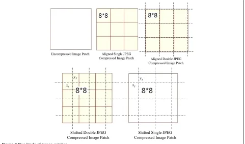
To facilitate subsequent discussions, we first give some definitions. An image patch with square shape and con-taining a number of 8 × 8 blocks can be classified into one of five categories as shown in Figure 2 (from left to right, top to bottom):
(i) Uncompressed: These patches are raw images and have never been JPEG compressed.
(ii) Aligned single JPEG compressed (ASJPEG in short): When the uncompressed image patches undergo a JPEG compression with the block structure aligned to the image patch, the output image patches are called ASJPEG patches. They are usually referred to as single JPEG image patches in the literature. (iii) Aligned double JPEG compressed (ADJPEG in
short): When the ASJPEG patches undergo another JPEG compression and the block structures of the two JPEG compressions are aligned with each other, the output image patches are called ADJPEG patches. They are usually referred to as double JPEG image patches in the literature.
(iv) Shifted double JPEG compressed (SDJPEG in short): When the ASJPEG patches undergo another JPEG compression and the block structures of the two JPEG compressions are different, the output image patches are called SDJPEG patches.
(v) Shifted single JPEG compressed (SSJPEG in short): Different from SDJPEG patches, when the image
patches before the shifted JPEG compression (with the block structure in dashed line) have never been compressed with the block structure starting from the top-left corner, the output image patches are called SSJPEG patches.
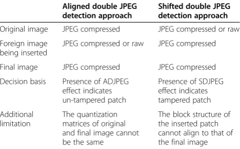
There are two general approaches for crop-and-paste tampering detection in JPEG images: aligned double JPEG detection and shifted double JPEG detection. Both approaches involve analyzing an image patch within a window aligned with the JPEG block structure of the final image, i.e., denoted hereafter as aligned patch, to detect any sign of tampering. Their differences and re-quirements are briefly summarized in Table 1. In most crop-and-paste tampering detection applications, both kinds of approaches are applied together to provide a more robust detection result.
The underlying rationale of the aligned double JPEG detection approach is as follows. If the original image has been JPEG compressed before and undergoes an-other JPEG compression after crop-and-paste tampering, image patches in the unmodified region in the final JPEG image (such as aligned patch I in Figure 3a) would have been compressed twice with the same block struc-ture and exhibit the aligned double JPEG effect, while image patches in the tampered region (such as aligned patch II in Figure 3a) will not show such effect. Algo-rithms in this approach look for untampered patch, i.e.,
Aligned Single JPEG Compressed Image Patch Uncompressed Image Patch
Aligned Double JPEG Compressed Image Patch
S
x
S
y
Shifted Double JPEG Compressed Image Patch
S
y
S
x
Shifted Single JPEG Compressed Image Patch
they detect the presence of aligned double JPEG effect, to establish the authenticity of the image patch. If such effect is absent, the patch is assumed to be tampered. It has been shown [8-11,17] that if the quality factors of the original and final image are the same, the detection performance would not be satisfactory. Recently, Huang et al. [18] proposed an aligned double JPEG detection al-gorithm that applied to the case where both the original and final images have the same quantization matrix. However, their approach cannot provide accurate detec-tion results for small image patch. Finally, the aligned double JPEG detection approach cannot detect the tam-pered region if the original image is uncompressed.
In contrast, the shifted double JPEG detection-based ap-proach [13-16] looks for tampered patch by detecting cues of tampering in an image patch. The basic idea is that if the inserted image region has been JPEG compressed
earlier, the second JPEG compression will leave some cues of shifted compression in the tampered region in the final image (such as the additional blocking artifacts [15,16]). For the aligned patches fully or partially located in the tampered region in the final image (such as aligned patch II in Figure 3a), such cues would exist, while for the aligned patches located in the unmodified region in the final image (such as aligned patch I in Figure 3a), such cues would be absent. Hence, the tampered region can be located by searching for all the aligned patches where the cues left by shifted compression exist. However, such cues vary greatly with image content and the quality factor of the inserted patch, and it is difficult to find a robust and discriminative feature for all situations. Moreover, this ap-proach needs a large image patch to obtain robust detec-tion results and is less effective for small patches.
In this paper, we propose a new shifted double JPEG detection method which also examines the characteris-tics of the inserted patch. Similar to [13,14], our algo-rithm considers image patches that are not aligned with the block structure of the final image (such as non-aligned patches I and II in Figure 3b). When analyzing the non-aligned patches in the final image, SDJPEG patches (such as non-aligned patch II in Figure 3b where the JPEG-compressed inserted patch undergoes a shifted JPEG com-pression, i.e., during JPEG compression of the final image) are located in the tampered region, while SSJPEG patches (such as non-aligned patch I in Figure 3b) are located in the untampered region. Note that the JPEG compression of the final image is aligned for the aligned patches in Figure 3a and shifted for non-aligned patches Figure 3b. In our algorithm, an exhaustive search on 63 possible
Figure 3Aligned (a) and shifted (b) image patches in the tampered image.
Table 1 Requirements of the crop-and-paste tampering detection methods
Aligned double JPEG detection approach
Shifted double JPEG detection approach
Original image JPEG compressed JPEG compressed or raw
Foreign image being inserted
JPEG compressed or raw JPEG compressed
Final image JPEG compressed JPEG compressed
Decision basis Presence of ADJPEG effect indicates un-tampered patch
Presence of SDJPEG effect indicates tampered patch
Additional limitation
The quantization matrices of original and final image cannot be the same
locations of the non-aligned image patches is performed to detect tampering. We will show in the experiment sec-tion that the increase in computasec-tional cost is worthwhile and our algorithm can achieve much better detection per-formance compared with the existing methods.
3 DCT coefficient analysis for SDJPEG patches
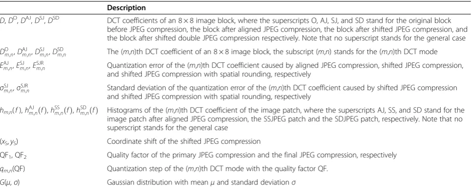
Since SDJPEG patches are generated by shifted JPEG compression on ASJPEG patches, we examine how the shifted JPEG compression affects the DCT coefficients. We first describe the effect of shifted JPEG compression on the DCT coefficients in Section 3.1. Then we derive a specific DCT coefficient model for SDJPEG patches in Section 3.2. The notation used hereafter is summarized in Table 2.
3.1 DCT coefficient variations caused by shifted JPEG compression
Before analyzing the effects on DCT coefficients caused by shifted JPEG compression, a simpler case, i.e., the ef-fects cause by aligned JPEG compression, is discussed.
Given an 8 × 8 image block A, its DCT coefficients
can be represented by DOð Þ ¼A DO m;nð ÞA
h i
1≤m;n≤8:
If block A undergoes an aligned JPEG compression
(as shown in Figure 4a) with the quality factor QF, the resulting DCT coefficients of blockA, denoted by
DAJð Þ ¼A DAJm;nð ÞA
h i
1≤m;n≤8 , will be a multiple of
the quantization step. Hence, aligned JPEG compression will induce a zero-mean quantization error (denoted by EAJ
m;nð ÞA ) for all the DCT coefficients, i.e.,
DmAJ;nð Þ ¼A DOm;nð Þ þA EAJm;nð ÞA ð1Þ
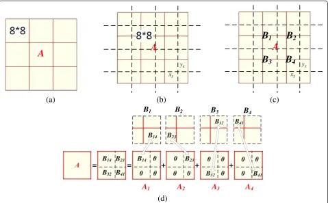
The discussions above can be extended to the case of
shifted JPEG compression. If block A undergoes a
shifted JPEG compression with a coordinate shift of (xS, yS) and quality factor QF (as shown in Figure 4b), the
DCT coefficients of block A become DSJð Þ ¼A
DSJm;nð ÞA
h i
1≤m;n≤8 . To derive the expression for DSJ
(A), we consider the DCT coefficients of the neighbor-ing 8 × 8 aligned blocks whose block structure coincides with the block structure of the shifted JPEG compres-sion on A. As shown in Figure 4c,d, block A is sur-rounded by four aligned blocks B1, B2, B3, and B4.
According to [19], the DCT coefficients of blockAand Bi (i= 1,2,3,4) are related by (details are given in
translation matrices to translate a specific block fromBito
Ai, as shown in Figure4. Note thatD(Hi1) andD(Hi2) (i=
DCT coefficients of block Bi i= 1,2,3,4 and thus before
compression DOð Þ ¼A X before JPEG compression, the block after aligned JPEG compression, the block after shifted JPEG compression, and the block after shifted double JPEG compression respectively. Note that no superscript stands for the general case
DO
m;n,DAJm;n,DSJm;n,DSDm;n The (m,n)th DCT coefficient of an 8 × 8 image block, the subscript (m,n) stands for the (m,n)th DCT mode EAJ
m;n,ESJm;n,ESJRm;n Quantization error of the (m,n)th DCT coefficient caused by aligned JPEG compression, shifted JPEG compression,
and shifted JPEG compression with spatial rounding, respectively
σSJ
m;n,σSJRm;n Standard deviation of the quantization error of the (m,n)th DCT coefficient caused by shifted JPEG compression
and shifted JPEG compression with spatial rounding, respectively
hm,n(f),hAJm;nð Þf ,h SS m;nð Þf ,h
SD
m;nð Þf Histograms of the (m,n)th DCT coefficient of the image patch, where the superscripts AJ, SS, and SD stand for the
image patch after aligned JPEG compression, the SSJPEG patch and the SDJPEG patch, respectively. Note that no superscript stands for the general case
(xS,yS) Coordinate shift of the shifted JPEG compression
QF1, QF2 Quality factor of the primary JPEG compression and the final JPEG compression, respectively
qm,n(QF) Quantization step of the (m,n)th DCT mode with the quality factor QF.
JPEG compression is performed on these aligned blocks. Based on the analysis about aligned JPEG compression in (1), DAJ(Bi) =DO(Bi) +EAJ(Bi), i= 1,2,3,4. The aligned JPEG compression on Biis equivalent to a shifted JPEG compression on A. Hence, after compression, the DCT coefficients of blockAwould change to
DSJð Þ ¼A X
denotes the shifted quantization error caused by shifted JPEG compression. For any DCT mode (m,n), the shifted quantization error ESJ
m;nð ÞA can be expressed by a linear combination of 4 × 64 = 256 zero-mean random variables,
i.e.,ESJ is the weighting parameter determined by D(Hi1) and D
(Hi2) (i= 1,2,3,4). According to the Central Limit Theorem
(CLT),ESJm;nð ÞA follows a zero-mean Gaussian distribution denoted byG 0;σSJ
m;n
with standard deviationσSJ
m;n.σSJm;n can be calculated with knowledge of the standard devia-tions of these 256 random variables (EAJ
u;vð ÞBi 1≤i≤4;1≤
u;v≤8) and the weighting coefficientsci
m;nðu;vÞ 1≤i≤4; 1≤u;v≤8.
In order to estimate the quantization error caused by aligned JPEG compression, we divide all the DCT coeffi-cients into two parts, i.e., the DC and AC components. For the DC component, since the quantization step is relatively small and the DC coefficients have a large dy-namic range, the quantization error caused by aligned JPEG compression approximately follows the uniform
distribution of −q1;1ðQFÞ
quantization step for the DC coefficients with the quality factor QF. For the AC components, according to [20], the AC components for a natural image approximately follow a Laplacian distribution. If we fit the coefficients
A
of AC components in the image patch to a Laplacian model, the standard deviations ofEAJ
u;vð ÞBi can be directly calculated with the quality factor QF. In addition, from (3), the weighting coefficients, ci
m;nðu;vÞ, are determined by the coordinate shift (xS,yS). Then the theoretical value
ofσSJ
m;ncan be calculated when QF and (xS,yS) are known.
To summarize, the shifted JPEG compression will in-duce a zero-mean Gaussian-distributed quantization error for all the DCT coefficients, and for different DCT coeffi-cients, the standard deviations of the shifted quantization error are different and can be calculated when the quality factor and the coordinate shift of the compression are known.
3.2 DCT coefficient analysis on SDJPEG patches
As discuss earlier, SDJPEG patches are constructed by per-forming shifted JPEG compression on ASJPEG patches. Similar to the ASJPEG patches, the DCT coefficients of SDJPEG patches also have certain specific distributions.
Given a gray scale image patch IMG consisting of a
number of 8 × 8 blocks aligned JPEG compressed with the quality factor QF1, let DAJm;nð Þk denote the (m,n)-th
DCT coefficient of the kth block in IMG. Since it has been JPEG compressed with quality factor QF1, DAJm;nð Þk
would be a multiple of the quantization step of the (m,n) th DCT mode (denoted by qm,n(QF1)). Hence,
consider-ing all the (m,n)th DCT coefficients in IMG, the normal-ized histogramhAJm;nð Þf of the (m,n)th DCT coefficients is
th DCT coefficient in IMG.
When the ASJPEG-compressed image patch IMG is transformed back to the spatial domain, two kinds of er-rors would be introduced. One is the truncation error. Since the luminance value of the gray scale image ranges from 0 to 255, any gray level greater than 255 or less than 0 will be truncated to 255 or 0, respectively. How-ever, as discussed in [21], such kind of error seldom ap-pears in natural images (about 1% of the image blocks have truncation errors), and any block with pixels having luminance value of 0 or 255 is discarded for further ana-lysis. The other is the rounding error, i.e., a rounding process will be carried out after IDCT to ensure that the luminance value in the spatial domain is an integer. Such rounding error in the spatial domain will lead to bias (denoted by Eroundingm;n ) in all the DCT coefficients.
Assuming that the rounding error in the spatial domain follows a zero-mean uniform distribution with range [−0.5, 0.5) and considering that the DCT transform is unitary, Eroundingm;n is Gaussian distributed with zero mean and variance 1/12 for all 1≤m, n≤8 according to the CLT [14].
After DCT-to-spatial transformation, the image patch undergoes a shifted JPEG compression with quality factor QF2 and the coordinate shifts (xS, yS). According to the
analysis in Section 3.1, the shifted JPEG compression will introduce a zero-mean Gaussian-distributed error term ESJm;nð Þk . The (m,n)th DCT coefficient of thekth block in efficient during the construction of the SDJPEG patch from the ASJPEG patch. Since Eroundingm;n and ESJm;nð Þk are both Gaussian distributed and independent of each other,
ESJRm;nð Þk also follows the Gaussian distribution with zero-mean and standard deviation ofσSJR
m;n¼ The histogram of the (m,n)th DCT coefficients after shifted double JPEG compression, denoted by hSDm;nð Þf , is
4 Detection of image patch with SDJPEG compression
The analysis in Section 3 shows that the DCT coefficient distribution of SDJPEG patches follows a weighted sum-mation of Gaussian components with the same standard deviation (as shown in (7) and Figure 5). However, in order to detect SDJPEG patches based on (7), two ques-tions have to be addressed: (i) How to obtain discri-minative features that capture the differences in the (m,n)th DCT coefficient distributions between SDJPEG and SSJPEG patches? (ii) How to select DCT modes which provide high discriminative power since the differences in the DCT
coefficient distributions of SDJPEG and SSJPEG patches would vary for different DCT mode? In the following, we will address these questions.
4.1 Discriminative feature extraction based on the (m,n)th DCT coefficients
For a specific DCT mode, say (m,n)th, the following detection algorithm is carried out by determining whether the histogramhm,n(f) is similar to that ofhSDm;nð Þf .
Given a specific quantization stepqm,n, we project the histogram hm,n(f) onto the interval −
qm;n
2 ; qm;n
2
, and the
(a1)
(a2)
(a3)
(b1)
(b2)
(b3)
(c1)
(c2)
(c3)
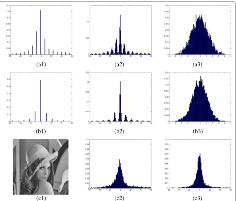
Figure 5DCT coefficient histograms for SDJPEG and SSJPEG patches from uncompressed 512 × 512 image. (a1 and b1)hAJ1;3ð Þf andhAJ3;1
f
ð Þwith QF1= 60.(a2 and b2)hSD1;3ð Þf andhSD3;1ð Þf with QF2= 90 and (xS,yS) = (4,4).(a3 and b3)Normalized distribution of the shifted double
sum of the histogram function within the interval is
de-According to (7), for SDJPEG-compressed image patches,hSDm;nð Þf follows a weighted summation of Gaussian components with a standard deviation of σSJR
m;n. Hence, shSDm;nð Þf would follow a specific distribution deter-mined by σSJR
m;n and qm,n. Based on the different ratios of qm;n=σSJR
m;n, shSDm;nð Þf can be obtained as follows. It should be noted that in our discussions, the Gaussian distribution, G(0, σ), is assumed to be bounded in [−3σ, 3σ], and any outliers are omitted.
(as shown in Figure 6a), i.e.,
shSDm;nð Þ ¼f Gaussian components would overlap with each other andshSDm;nð Þf would follow a distribution of a mixture of (p+ 1) Gaussian distributions (as shown in Figure 6b,c), i.e.,
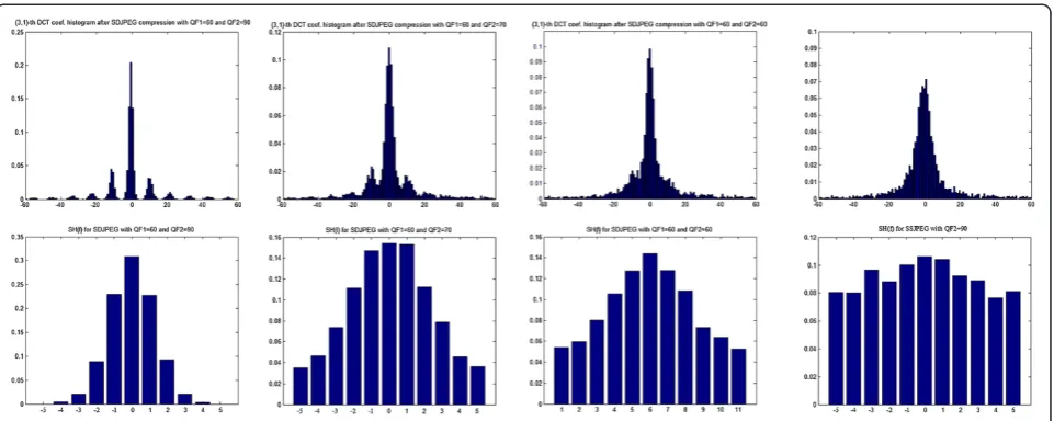
From (9) and (10) and Figure 6, it is observed that for the isolated or slight overlapping cases (p= 0 orp= 1), s hSDm;nð Þf has a distinctive peak at small |f|. The peak at small |f| becomes more prominent with largerqm;n=σSJRm;n. Such phenomenon does not occur for SSJPEG patches. Figure 7 illustrates shm,n(f) distributions of the image Lena.bmp of Figure 5 (c1) after SDJPEG and SSJPEG with various parameter settings.
From Figure 7, it is observed that the energy of shm,n (f) for SDJPEG image patches is concentrated on the center region whereas the energy ofshm,n(f) for SSJPEG patches is almost evenly distributed. It should be noted that when the size of the image patch is small, e.g., 64 × 64, the total number of DCT coefficients is small (64 coefficients in total), and it is difficult to estimate the actual distribution of the patch accurately and robustly using such limited data. In order to solve the above problem of inadequate data, the 1-D feature similar to that in [23] is adopted to differentiate between SDJPEG and SSJPEG image patches as follows:
Figure 6shSD
sm;n¼
For SDJPEG patches, the reference value of the fea-ture, denoted by sSD
m;n, can be derived from shSDm;nð Þf and is determined by σSJR
m;n and qm,n. The reference value of SSJPEG patch, denoted by sSS
m;n, is obtained as follows. Since the SSJPEG patch has never been compressed with the block structure starting from the top-left corner of the image patch, the DCT coefficients of SSJPEG can be assumed distributed approximately as the original un-compressed image patch [8,14]. Moreover, hSSm;nð Þf is equivalent to the distribution of the quantization error of the (m,n)th DCT component with the quantization stepqm,n. Hence,hSSm;nð Þf can be approximated using the aligned JPEG quantization error estimation approach in-troduced in Section 3.1. Then sSS
m;n can be derived from (8) and (11). Note that for the low-frequency DCT modes, the quantization step qm,n is relatively smaller compared with the dynamic range of the DCT coeffi-cients and thus shSSm;nð Þf is almost evenly distributed and sSS
m;n≈1>sSDm;n.
The final discriminative feature indicating the likelihood of an image patch having been SDJPEG compressed is derived by normalizing the extracted feature with the reference values sSDm;n and sSSm;n, i.e.,
snm;n¼ sm;n−sSDm;n
for SDJPEG patches and large for SSJPEG patches.
4.2 Discriminative feature extraction based on all the DCT coefficients
The analysis in Section 4.1 shows that snm,n for the SDJPEG image patches is smaller than those for the SSJPEG patches. Such phenomenon becomes more prom-inent with the increase of qm;n=σSJRm;n, and thus the DCT components with largerqm;n=σSJRm;nwould be more discrim-inative in SDJPEG detection. Our analysis in Section 3 shows that for a specific image,σSJR
m;ncan be estimated the-oretically when QF2and the shift coordinates (xS, yS) are
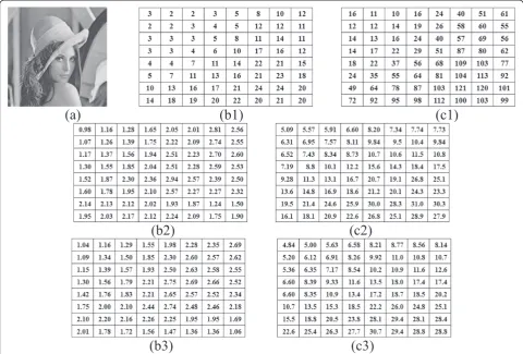
known. Figure 8 gives some examples of σSJRm;n 1≤m;n≤8 with different QF2and (xS,yS).
Figure 8 shows the following: (i) Shifted JPEG com-pression with lower quality (QF2) will introduce larger
spread to the DCT coefficients. (ii) σSJR
m;n for different DCT modes varies from each other and are not propor-tional to their corresponding quantization step. For in-stance, in Figure 8 (b2), the quantization steps for (2,1) and (2,2) are the same while σSJR2;1 and σSJR2;2 are quite dif-ferent. (iii) Even for the same DCT mode, the variations caused by shift JPEG compression do not remain con-stant with different coordinate shifts, e.g., for the (2,3)th DCT coefficient, σSJR2;3 is quite different when (xS, yS)
changes between (4,4) and (1,6). Hence, σSJR
m;n can be ob-tained by a table-lookup with the knowledge of QF2and
(xS,yS). In order to have large value ofqm;n=σSJRm;n, smaller Figure 7shm,n(f) Distributions of the image Lena.bmp of Figure 5 (c1) after SDJPEG and SSJPEG.h3,1(f) (the first row) andsh3,1(f) (the
values of σSJRm;n or larger values ofqm,nare preferred. For any value of the quality factor, Q= [qm,n] =λQdefault,
where Qdefault is the default quantization table defined
by the Independent JPEG Group (IJG) and λ is a
con-stant determined by the quality factor. Hence, we have qm;n
σSJR m;n¼λ
qdefaultðm;nÞ
σSJR
m;n ¼λdism;n 1≤m;n≤8 . It should
be noted that in practice, only QF2is known. We will
show how QF1can be estimated later.
The discriminative feature extraction considering all the DCT coefficients runs as follows:
1. Input the prior information: the image patch, the quality factor of the final compression QF2, and the
coordinate shift (xS,yS) (which is given by an
exhaustive enumeration on 63 possible coordinate shifts, see Section4.3).
2. According to the image patch, QF2and (xS,yS),
estimateσSJR¼ σSJR
m;n
h i
which is introduced by the
shifted double JPEG compression. Calculate the
discriminative table DIS = [dis(m,n)] for low frequencies (wherem+n< 8)
3. Sort all the DCT modes according to their discriminative value in descending order and the firstNc(Nc= 3 in our experiment) components
are selected to construct the candidate set, i.e., {ðm1;n1Þ;ðm2;n2Þ;…;ðmNc;nNcÞ}. Estimate the
quantization stepqmi;niðQF1Þ(for the unknown QF1)
of these DCT modes by analyzing their histograms. It should be noted that if the coefficients of a DCT mode in the candidate set has too many zero values (>80% of the total number of coefficients), the quantization step cannot be estimated accurately. Hence, considering the quantization noise caused by shifted compression, for any (mi,ni) whose
coefficients are concentrated in the range of
−3σSJR
mi;ni;3σ
SJR
mi;ni
h i
, i.e.,
Z 3σSJR
mi;ni
f¼−3σSJR
mi;ni hSD
mi;nið Þf ≥80%, Figure 8Examples ofσSJR
m;n 1≤m;n≤8, with different QF2and (xS,yS). (a)An example image Lena. (b1) The quantization matrix for QF2= 90.
(c1)The quantization matrix for QF2= 50.(b2, b3)EstimatedσSJRm;nwith QF2= 90, (xS,yS) = (4,4) and (1,6), respectively.(c2, c3)EstimatedσSJRm;nwith
the mode is discarded and replaced with the mode with the next largest discriminative value outside the candidate set.
4. For theith mode (mi,ni) in the candidate set, extract
the normalized discriminative feature for the (mi,ni)th
mode, i.e.,snmi,ni, using the approach described in
Section4.1with the estimatedσSJR
mi;ni andqmi;niðQF1Þ.
The final discriminative feature for the image patch, denoted bysnall, is obtained by averaging oversnmi;ni 1≤i≤Nc. In step 3, the quantization stepqm,n(QF1)
can be obtained by an exhaustive search among the reference SDJPEG'sshSDm;nð Þf whereshm,n(f) is the
most similar to. However, this approach is quite computationally expensive. SincehSDm;nð Þf exhibits periodic-like pattern with a period ofqm,n(QF1) to
reduce the complexity, the approach similar to that in [17] is adopted, i.e., the fast Fourier transform is applied to the histogramhSDm;nð Þf , and the peak of the spectrum with the DC removed is extracted to estimate the quantization step of the (m,n)th DCT modeqm,n(QF1). With the quantization step of the
(m,n)th DCT modeqm,n(QF1) estimated, the quality
factor QF1can be estimated by comparingqm,n(QF1)
with the default quantization tableQdefault. In order to
improve the robustness, allqm,n(QF1) values in the
candidate set are estimated. The median value of the predicted QF1is taken as the quality factor of the first
compression, and allqm,n(QF1) values in the candidate
set are refined using the estimated quality factor.
4.3 Crop-and-paste image tampering detection by detecting the SDJPEG effects
In order to detect crop-and-paste image tampering, the JPEG image is divided into a series of B×Bsubimages. Each B×B subimage is examined to detect whether it contains any image patch having SDJPEG effects, which runs as follows:
(i) For a specific coordinate shift (xS,yS) (0≤xS,yS≤7
and (xS,yS)≠(0, 0)), crop an image patch IMGxS;yS
from the subimage with the size of (B−8) × (B−8) and starting from (xS,yS).
(ii) With (xS,yS) and QF2, extract the discriminative
featuresnallfor IMGxS;yS. Then the SDJPEG effect
map (SEM) for (xS,yS) is set tosnall, i.e., SEM
(xS,yS) =snall.
(iii) Repeat steps (i) and (ii) for all the 63 possible coordinate shifts to obtain the SEM for theB×B subimage.
(iv) Compare SEM with those of the positive (containing SDJPEG patches) and negative (not containing any SDJPEG patch) samples in the training database to detect whether the subimage has been tampered with. The Fisher's linear discriminant analysis (LDA) [24] is adopted as the classifier in our approach.
(v) Loop through steps (i) to (iv) for allB×B subimages in the image to detect the suspicious regions that might have been tampered with.
5 Experiments and discussion
In this section, we first investigate the effectiveness of several key issues for the proposed approach, i.e., the quantization error estimation for shifted JPEG compres-sion, the primary quality factor estimation, and the pro-posed discriminative feature for SDJPEG detection. Then, we analyze the SDJPEG detection performance for image patches of various sizes and compared the detection per-formance with four state-of-the-art SDJPEG detection algo-rithms, i.e., Luo et al.'s [15] (Luo's in short), Chen and Hsu's [16] (Chen's in short), Bianchi and Piva's [13] (Bianchi I's in short), and Bianchi and Piva's [14] (Bianchi II's in short). Finally, we compare the image tampering detection performance of all five algorithms for two example images. The images in our experiments come from two widely used image databases, i.e., the UCID [25] and NRCS [26] image datasets, and all the original images are uncompressed.
5.1 Effectiveness evaluation of the proposed approach
5.1.1 Quantization error estimation for shifted JPEG compression
In order to evaluate the effectiveness of the proposed
ap-proach to estimate σSJR¼ σSJR m;n
h i
, 10,000 image patches
with the size 256 × 256 are randomly collected from the
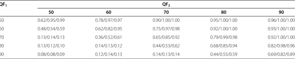
Table 3 Average estimation accuracy a1/a2/a3 of QF1with various patch sizes ((a1) 64 × 64; (a2) 128 × 128; (a3) 256 × 256), QF1and QF2
QF1 QF2
50 60 70 80 90
50 0.62/0.95/0.99 0.78/0.97/0.97 0.90/1.00/1.00 0.95/1.00/1.00 0.96/1.00/1.00
60 0.48/0.54/0.59 0.62/0.82/0.95 0.75/0.97/0.98 0.92/1.00/1.00 0.93/1.00/1.00
70 0.13/0.14/0.13 0.36/0.52/0.61 0.65/0.85/0.92 0.79/0.99/0.98 0.92/1.00/1.00
80 0.13/0.12/0.10 0.14/0.13/0.12 0.44/0.53/0.62 0.68/0.85/0.94 0.82/0.98/0.96
uncompressed images in the databases [25,26]. Then half of the image patches are used to generate the SSJPEG patches by shifted JPEG compression with the quality factor QF2randomly picked from 50 to 90 and random
selection of (xS, yS) ((xS, yS)≠(0, 0)). The other half of
the image patches are used to generate the SDJPEG by aligned JPEG compression with quality factor QF1
ran-domly picked from 50 to 90 and shifted JPEG compres-sion with quality factor QF2randomly picked from 50 to
90 and random selection of (xS,yS) ((xS,yS)≠(0, 0)). For
each image patch, the actual standard deviation of the quantization error caused by shifted JPEG compression
(denoted by σACT−SJR¼ σACTm;n−SJR
h i
) is recorded as the ground truth, and the average relative estimation error is adopted to evaluate the estimation performance, i.e.,
ηSJR¼
X8
m¼1
X8
n¼1
σSJR
m;n−σACTm;n−SJR
σACT−SJR
m;n
=64100% ð12Þ
The average relative estimation error ηSJR for the
above image patches using the proposed approach is 10.61%, which is much less than that using the rough approximation in [13,14] (214.94%). Hence, the pro-posed DCT coefficient model can better describe the ef-fects caused by shifted JPEG compression.
5.1.2 Primary quality factor estimation
To show the effectiveness of the proposed quantization step estimation approach, the following experiments have been carried out. For a specific patch size, QF1and
QF2, 500 SDJPEG patches are generated with random
selection of (xS,yS) ((xS,yS)≠(0, 0)). The average
estima-tion accuracy is given in Table 3.
From the table, it is observed that the estimation per-formance is improved with the increase of the patch size. It is because for larger size of the image patch, more data are collected to construct the histogram of the DCT coefficients and the period estimation approach will be more robust. On the other hand, the estimation perform-ance is also improved with the increase of QF2−QF1.
Such phenomenon can be explained as follows. From (7) and Figure 5 (a2 and b2), for SDJPEG image patches, the period in the histogram (i.e., the primary quantization step qm,n(QF1)) is large for low quality factor QF1 and the
standard deviation of the quantization noise with round-ing error, i.e., σSJR
m;n, is small for high quality factor QF2.
Hence when QF2−QF1is large, i.e., QF2−QF1≥10, the
Gaussian impulses in the histogram are non-overlapping or slightly overlapping and thus the period can be esti-mated accurately. However, when QF2−QF1is small, i.e.,
Table 4 Average classification accuracy, i.e., 1−(FAR + FRR)/2, in percent with various values of QF1and QF2for patch size of 64 × 64
QF1 QF2
50 60 70 80 90
50 51.86/50.40/50.96 51.55/55.15/53.51 54.89/70.08/62.07 56.32/78.95/70.02 62.29/82.12/76.71
50.90/58.28 51.56/71.32 54.29/86.77 56.58/91.65 63.01/96.66
60 51.31/50.26/49.34 50.57/50.87/52.10 51.40/55.24/56.21 53.92/70.50/62.51 59.02/78.39/71.51
51.95/54.05 50.34/56.96 51.75/69.80 54.31/90.71 60.89/92.17
70 50.62/50.44/50.70 50.33/50.55/51.09 51.30/51.13/51.07 52.71/59.49/60.02 56.33/70.25/65.25
50.80/51.10 49.60/52.04 50.45/59.19 52.63/71.76 57.22/92.12
80 50.42/50.92/50.47 49.62/50.63/50.98 51.62/50.42/50.09 50.49/51.91/51.77 54.34/58.41/59.39
49.79/50.83 49.77/50.44 49.66/53.49 50.33/56.28 53.90/75.50
90 50.44/50.27/49.26 49.86/49.41/49.20 49.89/49.91/49.45 49.39/50.37/49.62 50.02/50.14/50.48
49.13/51.70 50.64/50.39 49.87/50.45 50.48/51.68 50.26/58.96
Average classification accuracy, i.e., 1−(FAR + FRR)/2, in percent, with various values of QF1and QF2for patch size 64×64. The accuracies a1/a2/a3/a4/a5 in the
table are obtained by Luo's (a1), Bianchi I's (a2), Bianchi II's (a3), Chen's (a4), and the proposed method (a5), respectively. The best accuracies among the five methods investigated are boldfaced. Note that an accuracy of 50 is equivalent to random guess.
QF2−QF1≤ −20, the Gaussian impulses in the histogram
are highly overlapping and thus the periodic pattern al-most disappears in the histogram.
5.1.3 Effectiveness of the proposed discriminative feature
In order to investigate the effectiveness of the proposed discriminative feature snall, the distributions of snall for
SSJPEG and SDJPEG patches with the size 256 × 256 are analyzed. For SSJPEG patches, the quality factor QF2is
set to 70. For SDJPEG patches, the second compression quality factor QF2is also set to 70 and the primary
com-pression quality factor QF1is randomly picked from 50
to 70. The coordinate shift (xS, yS) is also selected
ran-domly in the range of 0≤xS, yS≤7, (xS, yS)≠(0, 0). The
histograms of snall in SSJPEG and SDJPEG patches are
given in Figure 9. It is observed thatsnallis usually small
for SDJPEG patches while it is large for SSJPEG ones, which demonstrates that snall is effective in
differentiat-ing SDJPEG and SSJPEG patches.
5.2 SDJPEG patch detection
To assess the performance of SDJPEG effects detection, we prepare the dataset as follows:
i. Image patches of three sizes, i.e., 64 × 64, 128 × 128 and 256 × 256 are used.
ii. An overall 25 {QF1,QF2} pairs are investigated with
QF1,QF2= {50,60,70,80,90}.
iii. For a specific {QF1,QF2} pair, 10,000 image patches
are randomly extracted from the uncompressed image database. The‘positive’samples are constructed by performing shifted JPEG
Table 5 Average classification accuracy for patch size of 128 × 128
QF1 QF2
50 60 70 80 90
50 51.81/52.95/53.82 52.62/56.83/55.13 58.25/72.74/67.85 64.26/81.69/77.62 74.29/89.93/86.55
51.88/70.35 52.30/85.51 59.59/96.14 65.94/97.35 75.15/99.29
60 50.91/51.96/51.45 51.33/52.02/51.37 54.12/61.65/59.72/ 58.48/74.19/70.39 69.45/81.78/79.76
51.29/59.59 51.48/74.70 55.08/82.15 58.44/97.26 70.78/98.76
70 50.00/50.58/51.15 51.26/50.05/50.53 52.64/53.55/53.97 53.76/64.37/64.07 62.79/76.49/78.42
50.12/50.23 50.99/58.90 51.57/72.26 54.28/95.48 62.53/98.57
80 50.10/50.24/50.00 51.48/50.17/51.36 50.11/50.30/50.44 50.99/52.79/52.42 57.24/65.44/68.36
50.28/49.76 50.67/49.96 50.05/59.82 51.00/71.59 58.44/91.08
90 50.25/49.36/49.58 50.26/49.65/49.02 49.47/49.19/50.25 49.86/52.09/52.67 52.46/53.31/53.25
50.30/50.26 49.53/49.55 50.20/50.93 49.39/57.92 52.33/72.54
The accuracies a1/a2/a3/a4/a5 in the table are obtained by Luo's (a1), Bianchi I's (a2), Bianchi II's (a3), Chen's (a4), and the proposed method (a5), respectively. The best accuracies among the five methods investigated are boldfaced. Note that an accuracy of 50 is equivalent to random guess.
Table 6 Average classification accuracy for patch size 256 × 256
QF1 QF2
50 60 70 80 90
50 53.24/58.51/59.75 56.39/66.82/64.12 65.63/78.59/71.01 75.82/89.20/86.18 84.39/94.19/93.59
52.84/72.78 57.54/86.17 67.88/95.66 77.05/98.54 86.72/99.81
60 50.91/53.52/52.40 55.02/60.36/57.57 58.23/65.21/63.58 67.78/78.18/71.37 80.62/89.98/88.14
50.08/60.94 54.81/81.80 60.39/84.75 69.72/98.00 81.64/99.78
70 50.81/51.82/49.92 50.68/53.94/52.15 52.14/57.31/57.99 59.04/68.23/69.21 74.18/84.12/82.61
49.97/50.13 50.00/59.53 53.63/75.09 61.30/97.45 75.50/98.82
80 49.62/51.80/51.42 49.39/50.88/49.50 50.04/50.48/50.31 53.55/58.32/59.16 64.82/72.41/71.58
50.53/50.47 49.38/50.17 50.71/60.92 52.89/77.11 64.57/96.87
90 49.99/50.38/50.42 50.72/50.56/49.39 50.02/50.24/49.78 50.03/52.93/51.13 54.39/54.27/53.67
50.26/49.34 50.99/50.27 49.67/51.16 49.66/60.97 54.85/75.09
compression with quality factor of QF1and random
coordinate shifts (xS,yS) (0≤xS,yS≤7 and (xS,yS)≠
(0, 0)) and then saving the image patches in JPEG format with QF2. The‘negative’samples are
constructed by directly saving the same
uncompressed image patches in JPEG with QF2.
Since in practice only QF2is available and QF1is
un-known to an algorithm, the following are the settings for the different algorithms evaluated:
1) For Luo's [15] and Chen's [16] approaches, the SVM is adopted as the classifier. In the training
(a) (b)
(c1) (c2) (c3)
(d1)
(d2)
(d3)
(e1)
(e2)
(e3)
Figure 10Tampering detection results using our approach compared with two recent state-of-the-art approaches. (a)Another example of JPEG image forgery.(b)Ground truth of(a), the tampered region are bounded by the highlighted contour.(c1 to c3)Tampered region detection by Bianchi I's method with {QF1,QF2} = (c1) {50,90}, (c2) {50,70}, (c3) {50,50}, respectively.(d1 to d3)Tampered region detection by
Bianchi II's method with {QF1,QF2} = (d1) {50,90}, (d2) {50,70}, (d3) {50,50}, respectively.(e1 to e3)Tampering region detection by the proposed
procedure, since QF1is unknown for each QF2, a
specific SVM is trained with the features extracted from half of the positive samples obtained from all possible selections of QF1= {50,60,70,80,90} and the
corresponding negative samples (there are overall 25,000 positive and 25,000 negative samples). In the testing procedure, the test samples are classified by their corresponding classifier with the knowledge of QF2.
2) For Bianchi I's [14] approach, with the knowledge of QF2, QF1is estimated by an EM algorithm. Then
the tampered region likelihood is calculated for each 8 × 8 block in the image patch, and the investigated image patch is classified as a SDJPEG patch if half of the 8 × 8 blocks in the patch are with the likelihood greater than 1. For Bianchi II's [13] approach, with the knowledge of QF2, QF1is achieved by an
exhaustive search.
3) For the proposed approach, QF1is estimated by the
method introduced in Section4.2.For each QF2,
SEM features for 630 positive samples (ten samples for each possible (xS,yS) with QF1randomly
selected) and 630 negative samples are adopted to train the classifier, and the rest (about 48,740 samples) are adopted for testing.
The detection performance obtained by our algo-rithm compared with the four existing methods is given in Tables 4, 5 and 6. For all the methods investigated, the clas-sification performance is affected by two key parameters: the patch size and the difference in quality factor between the first and second JPEG compressions, i.e., QF2−QF1.
From the table, the following observations can be made. First, the recognition accuracy increases substantially with the increase of patch size. As the features used in all five methods are based on statistical models, more data leads to better estimation of the models. Among all five approaches, our algorithm always outperforms the others especially when the patch size is small (64 × 64 for in-stance) since it requires less data to estimate a discrimina-tive model. Since only one or several small image patches are modified in most image tampering detection tasks, our algorithm is more appropriate in such applications.
Second, the detection performance is improved with the increase of QF2−QF1. It is because the lower quality
factor of the first JPEG compression will leave more traces of the compression history and the higher quality factor of the second JPEG compression will introduce less distortion to the image, which makes the traces left by the first compression easier to be detected. The pro-posed approach can achieve reasonable accuracies (above 80%) when QF2−QF1≥10 and high accuracies (above
90%) when QF2−QF1≥20 for 128 × 128 and 256 × 256
patches. However, when QF2−QF1≤ −20, the detection
performance is very poor for all approaches, i.e., the classi-fication accuracies are close to that of random guess (50%). The poor performance of the proposed approach is to be expected because when QF2< QF1,qm;n=σSJRm;nwill be very small for all the DCT modes andsSD
m;nwill be close to sSS
m;n. In addition, as shown in subsection 5.1.2, with small values ofqm;n=σSJRm;n, all the Gaussian components of hSDm;n
f
ð Þin (10) will highly overlap with each other and the esti-mation of QF1 will not be accurate especially when the
patch size is small.
5.3 Crop-and-paste image tampering detection
Figure 10 illustrates the tampering detection results using our approach compared with two recent state-of-the-art approaches [13,14]. The forgery image is made by cropping the image patch (enclosed by the highlighted boundary as shown in Figure 10 (b)) from another JPEG image with quality factor of QF1, pasting it to the original
image and saving as the forgery JPEG file with quality factor of QF2. Three different settings of {QF1,QF2}, i.e.,
{50,50}, {50,70}, and {50,90}, are investigated, and the de-tected tampered region is highlighted in the figures. Note that for all the three approaches, the corresponding pa-rameters are adjusted to ensure that the false alarm rate (FAR) is less than 10%. Moreover, the detection results undergo a 3 × 3 median filtering process to remove isolate detection errors. It is observed from the figures that the proposed algorithm can accurately detect and locate tam-pered region when {QF1,QF2} = {50,70} and {50,90}. It also
accurately points out some suspicious regions when {QF1,
QF2} = {50,50}. Compared with Bianchi and Piva's
ap-proaches [13,14], the proposed approach provides more accurate detection results due to (i) better estimation of the quantization error caused by shifted JPEG compres-sion and (ii) more discriminative information investi-gated by the adaptive DCT mode selection approach in Section 4.1 compared with that only DC mode is inves-tigated in [13].
6 Conclusions
In this paper, a new JPEG image tampering detection al-gorithm based on SDJPEG detection is presented. The
DCT coefficient distribution for the SDJPEG patches has been expressed by a statistical model, and a discrimina-tive feature has been proposed which can effecdiscrimina-tively dif-ferentiate between SDJPEG and SSJPEG patches. By an adaptive DCT mode selection scheme, several highly dis-criminative DCT modes are selected. We used several thousand SDJPEG and SSJPEG patches extracted from the UCID and NRCS image database to evaluate the per-formance of the proposed algorithm along with several existing algorithms. From the experimental results, the proposed algorithm can achieve much better results compared with the existing algorithms, especially when the patch size is small. We also performed experiments to detect and locate the tampered region of two test im-ages, where the proposed algorithm always outperforms the other algorithms investigated. As a result, the pro-posed algorithm has provided a new and effective solu-tion for SDJPEG detecsolu-tion and JPEG image forensics.
Appendix
Derivation of DCT coefficient from adjacent blocks
From Figure 4d, it is observed that block A can be
decomposed into four non-overlapped region, i.e., A1, A2, A3, and A4, andA=A1+A2+A3+A4. In order to
deriveAi=Hi1BiHi2, we just demonstrate the situation
wheni= 4 and the same analysis can be applied toi= 1,2,3 (Figure 11).
For the bottom right corner, A4 has the following
rela-tionship to B4:A4=H41B4H42, where H41¼ 0 0
. Iw and Ih are the identity matrices with
sizeh×handw×w, respectively;handware the number of rows and columns extracted. Since all unitary orthogonal transforms such as the DCT are distributive to matrix
multiplication [19], we haveD Að Þ ¼4 D Hð 41ÞD Bð Þ4 D Hð 42Þ
The authors declare that they have no competing interests.
Acknowledgements
The work described in this paper is supported by National Key Basic Research Program of China No. 2013CB329603 and NSFC Fund No. 61271319 and No. 61071152.
Author details
1
School of Information Security Engineering, Shanghai Jiaotong University, No. 800, Dong Chuan Rd, Shanghai 200240, China.2School of Information and Communication Technology, Gold Coast Campus, Griffith University, Queensland QLD4222, Australia.3Department of Electric and Electronic Engineering, Shanghai Jiaotong University, Shanghai 200240, China.
Received: 9 January 2014 Accepted: 13 June 2014 Published: 5 July 2014
References
1. X Wang, J Xue, Z Zheng, Z Liu, N Li, Image forensic signature for content authenticity analysis. J. Vis. Commun. Image. Repres.23(5), 782–797 (2012) 2. A Swaminathan, Y Mao, M Wu, Robust and secure image hashing. IEEE.
Trans. Info. Forensics. Sec.1(2), 215–230 (2006)
3. A Phadikar, SP Maity, M Mandal, Novel wavelet-based QIM data hiding technique for tamper detection and correction of digital images. J. Vis. Commun. Image. Represent.23(3), 454–466 (2012)
4. H Farid, A survey of image forgery detection. IEEE. Signal. Process. Mag. 2(26), 16–25 (2009)
5. AC Popescu,Statistical tools for digital image forensics. Ph.D. Thesis (Department of Computer Science, Dartmouth College, Hanover, NH, 2005) 6. AC Popescu, H Farid, Exposing digital forgeries in color filter array
interpolated images. IEEE. Trans. Signal. Proc.53(10), 3948–3959 (2005) 7. L Chen, W Lu, J Ni, W Sun, J Huang, Region duplication detection based on
Harris corner points and step sector statistics. J. Vis. Commun. Image. Represent. In Press
8. J Lukas, J Fridrich, Estimation of primary quantization matrix in double compressed JPEG images, inProceedings of Digital Forensic Research WorkshopCleveland, 2003), pp. 5–8
9. D Fu, YQ Shi, Q Su, A Generalized Benford's law for JPEG coefficients and its applications in image forensics, inProceedings of the SPIE Electronic Imaging, Security and Watermarking of Multimedia Contents IX, vol. 650, 5th edn. (Springer, San Jose, CA, 2007), pp. 1L1–1L11
10. T Pevny, J Fridrich, Detection of double-compression in JPEG images for applications in steganography. IEEE. Trans. Info. Forensics. Sec.3(2), 247–258 (2008)
11. H Farid, Exposing digital forgeries from JPEG ghosts. IEEE. Trans. Info. Forensics. Sec.4(1), 154–160 (2009)
12. SM Ye, QB Sun, EC Chang,Detecting digital image forgeries by measuring inconsistencies of blocking artifact, in Proceedings of IEEE International Conference on Multimedia and Expo(China, Beijing, 2007). pp. 12–15 13. T Bianchi, A Piva, Detection of nonaligned double JPEG compression based
on integer periodicity maps. IEEE. Trans. Info. Forensics. Sec.7, 2 (2012) 14. T Bianchi, A Piva, Image forgery localization via block-grained analysis of
JPEG artifacts. IEEE. Trans. Info. Forensics. Sec.7, 3 (2012)
15. W Luo, Z Qu, J Huang, G Qiu, A novel method for detecting cropped and recompressed image block, inProceedings of the IEEE International Conference on Acoustic, Speech and Signal Processing (ICASSP’07), vol. 6, 2nd edn. (IEEE, Piscataway, Honolulu, Hawaii, pp. 217–220
16. YL Chen, CT Hsu, Detecting recompression of JPEG images via periodicity analysis of compression artifacts for tampering detection. IEEE. Trans. Info. Forensics. Sec.6(2), 396–406 (2011)
17. Z Lin, J He, X Tang, CK Tang, Fast, automatic and fine-grained tampered JPEG image detection via DCT coefficient analysis. Pattern. Recogn. 42(11), 2492–2501 (2009)
18. FJ Huang, JW Huang, YQ Shi, Detecting double JPEG compression with the same quantization matrix. IEEE. Trans. Info. Forensics. Sec.5(4), 848–856 (2010) 19. SF Chang, DG Messerschimitt, Manipulation and compositing of MC-DCT
compressed video. IEEE. J. Select. Areas. Commun.13(1), 1–11 (1995) 20. R Reininger, J Gibson, Distributions of the two-dimensional DCT coefficients
for images. IEEE. Trans. Commun.31(6), 835–839 (1983)
21. Z Fan, RL de Queiroz, Identification of bitmap compression history: JPEG detection and quantizer estimation. IEEE. Trans. Image. Process. 12(2), 230–235 (2003)
22. AC Popescu, H Farid, Statistical tools for digital forensics. Lect. Notes. Comput. Sci.3200, 395–407 (2005)
23. W Luo, J Huang, G Qiu, JPEG error analysis and its application to digital image forensics. IEEE. Trans. Info. Forensics. Sec.5(3), 480–491 (2010) 24. RO Duda, PE Hart, DG Stork,Pattern Classification, 2nd edn.
(Wiley-Interscience, USA, 2000)
25. G Schaefer, M Stich, UCID: an uncompressed color image database, in
Proceedings of the SPIE Storage and Retrieval Methods and Applications for Multimedia, vol. 530, 7th edn. (Springer, San Jose, CA, 2003), pp. 472–480 26. NRCS Photo Gallery, 2005. http://photogallery.nrcs.usda.gov/res/sites/
photogallery/
doi:10.1186/1687-6180-2014-101