ISSN 2348 – 7968
Layout of a Simple Multiple Antenna System with Isolation
Characteristics
T.Rubesh kumar1, N.Jeevitha2
1
Associate Professor, Department of Electronics and Communication Engineering, Prathyusha Engineering College, Thiruvallur, Tamilnadu, India
2
M.E Student, Department of Communication Systems, Prathyusha Engineering College, Thiruvallur, Tamilnadu, India
Abstract
A simple multiple-input-multiple-output (MIMO) antenna with a size of 120 * 140 mm is proposed for GPS/LTE applications. The wireless communication high data rate is achievable by introducing more than one antenna in transmitter and receiver terminals as MIMO antenna. The proposed antenna consists of four monopole antenna with microstrip-feed printed on one side of the substrate, and slots are added to the ground plane to enhance the isolation between the ports. The good isolation achieved, despite the fact that four antenna elements are printed on a compact MIMO antenna system. The proposed antenna is simulated by ADS software.
Keywords: Slot, Isolation, Long Term Evolution, Global Positioning System.
1. Introduction
Multiple-Input-Multiple-Output or MIMO is one of the latest forms of smart antenna technology to improve communication performance. Multiple-input-multiple-output (MIMO) antenna systems are a key enabling technology for modern fourth-generation (4G) wireless systems. In the commercial area, MIMO used with orthogonal frequency-division multiple access technology, which supports both diversity coding and spatial multiplexing. Recently, microstrip antenna designers also employ MIMO technology, where they use two or more radiating patches in the design for transmission.
More than one antenna on the transmitter and/or recipient of a wireless system will increase data rate and performance or scale down ISI and obstruction from different smart antennas without increasing transmits power or bandwidth. MIMO strategies are expert than single-antenna to-single-antenna techniques. Sensitivity to fading is extremely reduced by the spatial diversity by multiple spatial paths [1]. In this article [2], they discussed about the distinct parameter which could be needed to analyze the performance of MIMO antenna and listed
some printed MIMO antenna. Main goal is to accomplish high isolation mechanisms to lower the mutual coupling between the closely spaced antennas.
Various papers focused to scale back the mutual coupling through distinctive enhancement method. MIMO antenna contains two planar Monopole set oppositely to each other to accomplish high isolation between the ports [3]; the MIMO antenna system is made of two symmetric printed monopole antenna and a decoupling method to accomplish isolation further noteworthy than -15 dB [4]; two U-shaped slots are acquainted with to reduce the coupling between the MIMO antenna elements [5]. Two types of antenna elements imprinted on different sides of the substrate to achieve extraordinary isolation and a series of slits are etched in the ground plane that enhances the isolation stage by level of 10 dB [6]. The Procedure contains in embedding a parasitic lossless radiating elements between the antennas with optimized position, measurements, and size. It obtained isolation higher than 15 dB [7].The EBG likewise improved array performance by eliminating with blind spots and grating lobes [8].To lower the coupling and thus improve the antenna’s total efficiency, optimized neutralization lines were embedded between the radiating elements [9].The isolation is improved by reversed Y formed stub on ground plane. The noteworthy increment in port isolation nearly as good as reduction in mutual coupling with the help of utilizing the stub has helped in miniaturizing the antenna [10]. This article planned a straightforward layout for reducing mutual coupling between two planar monopole by introducing slots in the ground plane [11].
The unconventional configuration is accomplished via cutting slots on the one radiating fringe of the patch antenna. The slot loading antennas provide the
higher performance in resonant frequency, return
ISSN 2348 – 7968
resonant frequency is gradually decreases with the increase of slot lengths [12].The Rectangular Microstrip Patch Antenna has been analyzed for the changing slot width and length in patch and therefore the ground plane. The impact on resonant frequency shift is more pronounced for slots in patch than slots in ground , furthermore observed that bandwidth ,gain are more influenced because of slots in patch than slots in ground plane [13].In this paper, a MIMO antenna is proposed for Global Positioning System and Long Term Evolution applications. The proposed MIMO antenna system includes four microstrip feed line printed monopole antennas with a rectangular slotted radiating element and ground plane. To improve the isolation between the ports, four slots are introduced at every corner of the ground plane. With a specific end goal to acquire the MIMO gain, the antenna elements are orthogonal to each other.
In this paper, a MIMO antenna is proposed for Global Positioning System and Long Term Evolution applications. The proposed MIMO antenna system includes four microstrip feed line printed monopole antennas with a rectangular slotted radiating element and ground plane. To improve the isolation between the ports, four slots are introduced at every corner of the ground plane. With a specific end goal to acquire the MIMO gain, the antenna elements are orthogonal to each other. Hence the radiation patterns are statistically independent to each other.
2. Proposed Antenna Geometry
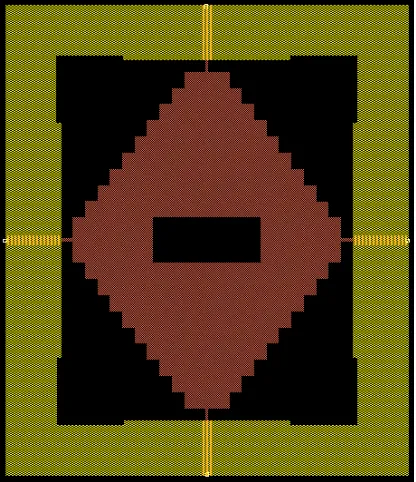
The proposed MIMO antenna system is intended for Global Positioning System (1.575 GHz) and Long Term Evolution (2.6 GHz) applications, as appeared in Fig-1. The size of the outlined MIMO antenna is 120 x 140 mm on a FR-4 substrate with the thickness of 1.6mm, the radiator and the ground plane are on the top and base of the dielectric substrate, individually, and both are made of copper material with thickness t=0.035mm. The radiator of the MIMO antenna system is planned as the shape rectangular radiator with four-ventured line at the corners. The ground plane is balanced by introducing four slot in each corner to decrease the mutual coupling and rectangular slot introduced at center of around 32 x 13 mm in radiator.
In order to overcome the isolation between the ports, two strategies have been used. The primary system exploits the opposite structure of the ports, that the most clear system to decrease coupling between adjoining the antennas. The
extra material. Consequently, this structure is completely promising as an approach to manage the mutual coupling issue. Polarization diversity is a technique where distinctive polarizations are used to improve the performance of MIMO system. As showed by the layout structure, the ports are orthogonal to each other; different polarization (level and vertical polarizations) was procured.
Fig.1. Geometry of proposed four port MIMO antenna system
3. Simulation Results
The proposed MIMO antenna system simulated using the ADS software. It is modeled on a FR-4 substrate of dielectric constant value of 4.3 and thickness h=1.6mm with the tangent loss of 0.025.The radiator and ground plane thickness are of about 0.035mm.The resulting antenna resonates at 1.575 GHz and 2.6 GHz frequency, which is suitable for GPS and LTE applications respectively.
ISSN 2348 – 7968
1.2 1.4 1.6 1.8 2.0 2.2 2.4 2.6 2.8
1.0 3.0
-15 -10 -5 0 5
-20 10
freq, GHz
d
B
(S
(1
,1
))
Fig .2. Reflection coefficients of the MIMO antenna system in port 1.
1.2 1.4 1.6 1.8 2.0 2.2 2.4 2.6 2.8
1.0 3.0
-30 -20 -10 0 10
-40 20
freq, GHz
d
B
(S
(4
,4
))
Fig .3. Reflection coefficients of the MIMO antenna system in port 4.
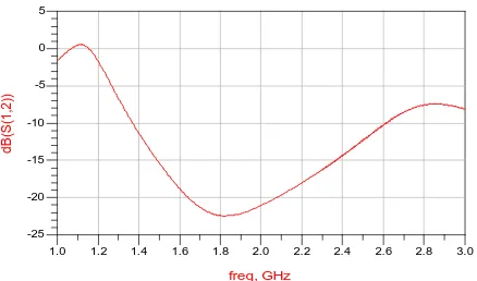
The isolation curve lies below -15 dB as shown in Fig -4, Fig -5, Fig -6, Fig -7, Fig -8, and Fig -9.
1.2 1.4 1.6 1.8 2.0 2.2 2.4 2.6 2.8
1.0 3.0
-20 -15 -10 -5 0
-25 5
freq, GHz
d
B
(S
(1
,2
))
Fig .4. Simulated isolation between port 1 and 2.
1.2 1.4 1.6 1.8 2.0 2.2 2.4 2.6 2.8
1.0 3.0
-20 -15 -10 -5
-25 0
freq, GHz
d
B
(S
(1
,3
))
Fig .5. Simulated isolation between port 1 and 3.
1.2 1.4 1.6 1.8 2.0 2.2 2.4 2.6 2.8
1.0 3.0
-20 -15 -10 -5 0
-25 5
freq, GHz
d
B
(S
(1
,4
))
ISSN 2348 – 7968
1.2 1.4 1.6 1.8 2.0 2.2 2.4 2.6 2.8
1.0 3.0
-20 -15 -10 -5 0
-25 5
freq, GHz
d
B
(S
(2
,3
))
Fig .7. Simulated isolation between port 2 and 3.
1.2 1.4 1.6 1.8 2.0 2.2 2.4 2.6 2.8
1.0 3.0
-30 -20 -10 0
-40 10
freq, GHz
d
B
(S
(2
,4
))
Fig .8. Simulated isolation between port 2 and 4.
1.2 1.4 1.6 1.8 2.0 2.2 2.4 2.6 2.8
1.0 3.0
-20 -15 -10 -5 0
-25 5
freq, GHz
d
B
(S
(3
,4
))
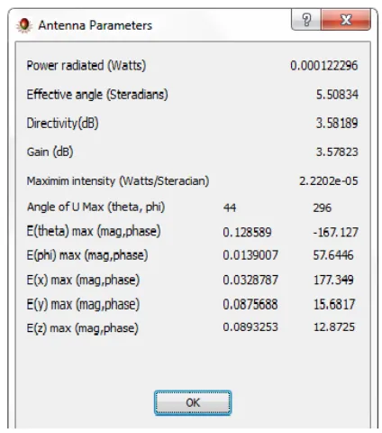
Fig. 10. Measures of Various antenna parameters
4. Conclusions
In this paper, a slotted MIMO antenna is proposed, to achieve high isolation between the ports. A slotted MIMO antenna was designed at 1.575 GHz and 2.6 GHz frequency. In addition, simulated results are obtained. The return loss achieved for this antenna is -18 dB and 40 dB for the ports 1 and 4 respectively. Since port 1 and 3, 2 and 4 are orthogonal to each other their response are similar and then gain 3.57 dB and directivity 3.58 dB is obtained.
References
[1] D. W. Bliss, K. W. Forsythe, and A. M. Chan, “MIMO wireless communication, “Lincoln Lab. J., vol. 15, pp. 97–126, 2005.
[2] M. S. Sharawi, “Printed multi-band MIMO antenna systems and their performance metrics,” IEEE Antennas Propag. Mag., vol. 55, no. 5, pp. 218–232, Oct. 2013.
ISSN 2348 – 7968
[6] H. Li, J. Xiong, and S. He, “A compact planar MIMO antenna system of four elements with similar radiation characteristics and isolation structure,” IEEE Antennas Wireless Propag. Lett., vol. 8, pp. 1107–1110,2009.
[7] X. Zhou, X. L. Quan, and R. L. Li, “Dual-band WLAN diversity antenna System with high port-to-port isolation,” IEEE Antennas Wireless Propag. Lett., vol. 11, pp. 244–247, 2012. [8] M. Abedin andM. Ali, “Effects of a smaller unit cell planar EBG structure on the mutual coupling of a printed dipole array,” IEEE Antennas Wireless Propag. Lett., vol. 4, pp. 274–276, 2005.
[9] S. Dossche, S. Blanch, and J. Romeu, “Optimum antenna matching to minimize signal correlation on a two-port antenna diversity system,” Electron. Lett., vol. 40, no. 19, pp. 1164– 1165, 2004.
[10] A. Najam, Y. Duroc, and S. Tedjini, “UWB-MIMO antenna with novel stub structure,” Prog. Electromagn. Res. C, vol. 19, pp. 245–257, 2011.
[11] S. L. Zuo, Y. Z. Yin, W. J.Wu, Z. Y. Zhang, and J.Ma, “Investigations of reduction of mutual coupling between two planar monopoles using two slots,” Prog. Electromagn. Res. Lett., vol. 19, pp. 9–18, 2010.
[12] S. Bhunia, “Effects of Slot Loading on Microstrip Patch Antennas,” International Journal of Wired and Wireless Communications Vol.1, Issue 1, October, 2012.