Vol. 4, Issue 4, April 2016
Performance Analysis of 3GPP Spatial
Channel Model Based Propagation
Environments For 4x4 MIMO Systems
Nikita Jain1, Shivpratap Pandey2
M.Tech Scholar, Dept. of ECE., SS College of Engineering, Udaipur, India1
Asst. Professor, Dept. of ECE., SS College of Engineering, Udaipur, India2
ABSTRACT: This paper presents error rate performance analysis of 3GPP spatial channel models for various environments. The bit error rate vs. signal to noise ratio plots reveal the comparative distortion offered by these environments to the transmitted signal. Simulation results reveal that the suburban macrocell environment offers least distortion to any transmitted signal as compared to other environments.
KEYWORDS: MIMO, 3GPP.
I. INTRODUCTION
Next generation wireless communication system will demand purely high speed communication links, high quality multimedia and data services with high efficiency and reliability. In order to achieve high data rate services such as online gaming, video conferencing or web browsing, the next generation wireless communication systems would have to improve their range, quality of service (QoS), bandwidth, throughput and power efficiency [1].
MIMO is an emerging wireless technology conceived in the mid 90’s. Multiple Input Multiple Output, popularly known as MIMO, is a radio communication technology used in WI-FI, Long Term Evolution (LTE) and various other RF, wireless and radio technology to achieve improved link performance, higher data throughputs and significant improvement in data transmission credibility [2]. It has been standardized for 3G, 4G, wireless LANs and is now in far
flung commercial use [3]. Multiple Input Multiple Output technologyhas achieved widespread attention in recent years
as a promising wireless technology. Such systems offer the dual benefits of wireless channel fading mitigation through diversity reception and link throughput enhancement through Spatial Multiplexing [4].
The agency responsible for developing specifications of Long Term Evolution (LTE) is 3rd Generation Partnership
Project (3GPP). The 3rd Generation Partnership Project (3GPP) unites [Seven] telecommunications standard development organizations (ARIB, ATIS, CCSA, ETSI, TSDSI, TTA, TTC), known as “Organizational Partners” and provides their members with a stable environment to produce the reports and specifications that define 3GPP technologies [5].
The project covers cellular telecommunications network technologies, including radio access, the core transport network, and service capabilities - including work on codecs, security, and quality of service - and thus provides complete system specifications. The specifications also provide hooks for non-radio access to the core network, and for interworking with Wi-Fi networks [5].
3GPP has defined propagationenvironments for LTE and other concurrent standards which are broadly classified as
Urban Microcell Environment
Urban Macrocell Environment
Suburban Macrocell Environment
Vol. 4, Issue 4, April 2016
II. MIMOSYSTEM MODEL
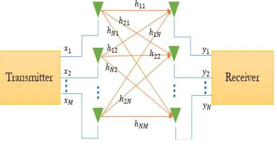
MIMO system model consists of three components, mainly transmitter, channel and receiver. Usually, a MIMO system consists of M transmit and N receive antennas as shown in figure 1. It is called a MIMO (N, M) system. All the antennas at transmitter side can send their information simultaneously in the same bandwidth of a radio channel. In the ideal case, each path is assumed to be statistically independent from the others. Independent data can be sent from each antenna, increasing the capacity of the system [6].
Let H be the channel matrix of N x M dimensions, where M is a number of transmit antennas and N is a number of receive antennas. Channel between Nth receive antenna and Mth transmit antenna is denote as hNM.
All the elements in the fading channel matrix are considered independent identically distributed (i.i.d.) complex Gaussian random variables (GRVs) and in the same way, the elements of the noise vector are also complex Gaussian random variables (Guassianwave.com).
Figure 1: MIMO System Model
Herein, consider a transmitted vector x = [x x … x ] , The vector is then
transmitted via a wireless MIMO channel characterized by the channel matrix Hwhoseelements
h,(lat fading coef icient)~ ℕ(0,σ ) is the random Gaussian complex channel coefficient between the jthreceive and
ithtransmit antennas with zero mean and unity variance. The received vector y = [y y … y ] can then be given
as following. Therefore received signal can be modelled as [6]
y = Hx + n (1)
where y is the received signal vector, xis transmitted signal vector, n is the noise vector. The given system can be represented in matrix format as
y y .. .. y
=
h h … h
h .. ..
h .. ..
… h
.. ..
h h h
x x .. .. x
+ n n .. .. n
(2)
III.3GPPSPATIAL CHANNEL MODELS
3.1 Urban Microcell Environment
This environment corresponds to the metro cities and developed infrastructure areas. The signals in this area are often non line-of-sight and suffer various multipaths [5]. The salient features of Urban Microcell Environment simulated in this work are [5]:
• Densely populated
Vol. 4, Issue 4, April 2016
• Cell radius: 400m to 2Kms
• Fading: Log Normal Shadow Fading
• Distance b/w transmitting antenna: 2λ
• Distance b/w receiving antenna: 0.4λ
• Carrier frequency: 2GHz
3.2 Urban Macrocell Environment
As the name suggests, Urban Macrocell refers to urban areas but with bigger cell radius. This type of environment occurs in densely populated city areas where infrastructure comprises of both, skyscrapers and low rise buildings [5]. The specifications of Urban Macrocell Environment used in this work are:
• Densely populated
• Medium infrastructure, cities and towns.
• Cell radius: Up to 30Kms
• Fading: Log Normal Shadow Fading
• Distance b/w transmitting antenna: 4λ
• Distance b/w receiving antenna: 0.4λ
• Carrier frequency : 2GHz
3.3 Suburban Macrocell Environment
Suburban Macrocell corresponds to rural areas, small towns and open grounds with bigger cell radius. This type of environment is generally found in villages, city outskirts and highways. In Indian context, this environment is still prominent in most parts of the country and needs proper connectivity infrastructure. Therefore it is of utmost importance to study this environment for suitable detection algorithms with minimum complexity [5].
The specifications of Urban Macrocell Environment used in this work are:
• Sparsely populated
• Mild infrastructure, villages, open fields
• Cell radius: up to 30Kms
• Fading: Log Normal Shadow Fading
• Distance b/w transmitting antenna: 4λ
• Distance b/w receiving antenna: 0.4λ
• Carrier frequency : 2GHz
IV.RESULTS AND DISCUSSION
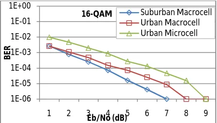
Figure 2(a), 2(b) and 2(c) shows the error rate performance of all three environments for 16-QAM, 64-QAM and 256-QAM schemes respectively using ZF detector.
Figure 2(a): BER performance of 3GPP Environments on 16-QAM
1E-06 1E-05 1E-04 1E-03 1E-02 1E-01 1E+00
1 2 3 4 5 6 7 8 9
B
E
R
Eb/No (dB)
16-QAM Suburban Macrocell
Vol. 4, Issue 4, April 2016
Figure 2(a) shows the BER performance of three environments on 16-QAM. It shows the urban microcell performs
worst of all, followed by urban macrocell and then suburban macrocell. Urban microcell achieves BER of 10-4 at 5.5dB
whereas the same is achieved by Suburban macrocell at 3dB SNR.
Figure 2(b): BER performance of 3GPP Environments on 64-QAM
Figure 2(b) shows the BER performance of three environments on 64-QAM. Similar to 16-QAM, here also the urban microcell performs worst of all, but the performance gap is less as compared to 16-QAM. It is followed by urban
macrocell and then suburban macrocell. Urban microcell achieves BER of 10-4 at 5.6dB whereas the same is achieved
by Suburban macrocell at 3.2dB SNR.
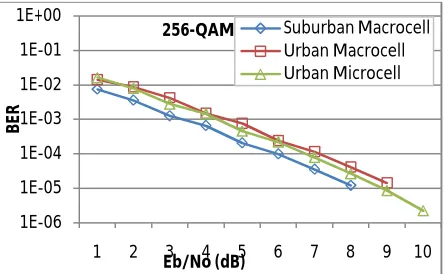
Figure 2(c): BER performance of 3GPP Environments on 256-QAM
Figure 2(c) shows the BER performance of three environments on 256-QAM. Unlike the previous modulation schemes, here, urban macrocell performs worst of all. It is followed by urban microcell and finally the suburban macrocell.
Urban macrocell achieves BER of 10-4 at 6.5dB whereas the same is achieved by Suburban macrocell at 5.5dB SNR. Figure 2(a,b,c) reveals that the suburban macrocell environment offers least disruption to the transmitted signal for all
modulation schemes. For 16-QAM and 64-QAM, urban microcell performs worst of all, whereas for 256-QAM urban macrocell performs worst.
V. CONCLUSION
To conclude, suburban macrocell offers least disruption to any transmitted signal, due to less multipath and often available line-of-sight between transmitter and receiver. The results obtained via simulations will play a significant role in establishing the infrastructure for last mile connectivity and will lead to improvement in Quality of Service (QoS).
1E-06 1E-05 1E-04 1E-03 1E-02 1E-01 1E+00
1 2 3 4 5 6 7 8 9
B
ER
Eb/No (dB)
64-QAM Suburban Macrocell
Urban Macrocell Urban Microcell
1E-06 1E-05 1E-04 1E-03 1E-02 1E-01 1E+00
1 2 3 4 5 6 7 8 9 10
B
E
R
Eb/No (dB)
Vol. 4, Issue 4, April 2016
REFERENCES
[1] W. H. Chin, Z. Fan, R. Haines, “ Emerging Technologies and Research Challenges for 5G Wireless Networks,” Toshiba Research Europe Limited, Bristol, 2014.
[2] D.W. Bliss, K. W. Forsythe, A. M. Chan “MIMO Wireless Communication,” Lincoln Laboratory Journal. Vol. 15, No. 1, 2005.
[3] J. Farooq, B. Rauf “An Overview of Wireless LAN Standards IEEE 802.11 and IEEE 802.11e,” in Department of Computing Science Umeå University Sweden.2013.
[4] I.F. Akyildiz, D. M. Estevez, E. C. Reyes, “The evolution to 4G cellular systems: LTE-Advanced” in Physical Communication 3 (2010) 217– 244
[5] Spatial channel model for Multiple Input Multiple Output (MIMO) simulations. 3GPP. http://www.3gpp.org/DynaReport/25996.htm
[6] D. Seethaler, H. Artes, and F. Hlawatsch, “Detection Techniques for MIMO Spatial Multiplexing Systems” in E&I, vol. 122, no. 3, pp. 91–96, March 2005.
BIOGRAPHY
Nikita Jain completed her B.Tech degree in Electronics and communication engineering in 2012. Currently she is pursuing M.Tech in Digital Communication from Rajasthan Technical University.